AJSDC615 User Guide
Page 3
...displays (MODE CHECK button function 45 Marker check screen displays (MARKER SELECT button function 45 Checking the return video signal on the viewfinder 45 4-8 Menu-driven function setup 46 4-8-1 Setting the USER SW GAIN switching ........ 46 4-8-2 4-8-3 Selecting the video output signals 46 Selecting the F.AUDIO LEVEL control function 47 4-8-4 Allocating functions to the USER MAIN, USER1 and USER2 buttons 47 4-8-5 Setting the color temperature manually ....... 48 4-9 Data handling 48 4-9-1 Handling the setup card 48 4-9-2 Setup card operations 49 4-9-3 How to use the user...
...displays (MODE CHECK button function 45 Marker check screen displays (MARKER SELECT button function 45 Checking the return video signal on the viewfinder 45 4-8 Menu-driven function setup 46 4-8-1 Setting the USER SW GAIN switching ........ 46 4-8-2 4-8-3 Selecting the video output signals 46 Selecting the F.AUDIO LEVEL control function 47 4-8-4 Allocating functions to the USER MAIN, USER1 and USER2 buttons 47 4-8-5 Setting the color temperature manually ....... 48 4-9 Data handling 48 4-9-1 Handling the setup card 48 4-9-2 Setup card operations 49 4-9-3 How to use the user...
AJSDC615 User Guide
Page 6
... excellence. ≥ Power-saving management function In order to reduce its power consumption efficiently, the unit has a function that shuts down on the LCD display window. ≥ Front audio level control The unit's front panel is for not leaving behind superfluous cuts when a cut turns out to be given precedence. ≥ DVCPRO format supported SDC615 The VTR unit compresses the images using a component digital recording system that uses the latest...
... excellence. ≥ Power-saving management function In order to reduce its power consumption efficiently, the unit has a function that shuts down on the LCD display window. ≥ Front audio level control The unit's front panel is for not leaving behind superfluous cuts when a cut turns out to be given precedence. ≥ DVCPRO format supported SDC615 The VTR unit compresses the images using a component digital recording system that uses the latest...
AJSDC615 User Guide
Page 7
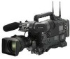
....) Hard carry case: AJ-HT901 Video camera-recorder: AJ-SDC615 AJ-SDC905 AC adapter: AJ-B75 SD memory cards Multimedia cards Cleaning tape: AJ-CL12MP Cassette tapes: AJ-5P23MP AJ-5P33MP AJ-P12MP AJ-P24MP AJ-P33MP AJ-P66MP Devices compliant with the IEEE 1394 standard. This connector can be connected with an external unit using an IEEE 1394 cable. 1-3 System configuration Microphone kit: AJ-MC700 UniSlot ® wireless microphone receiver: Sennheiser EK3041 Extension control unit: AJ-EC3P Viewfinders: AJ-VF15B AJ-VF20WB Microphone holder: AJ-MH700 Lens (Bayonet type...
....) Hard carry case: AJ-HT901 Video camera-recorder: AJ-SDC615 AJ-SDC905 AC adapter: AJ-B75 SD memory cards Multimedia cards Cleaning tape: AJ-CL12MP Cassette tapes: AJ-5P23MP AJ-5P33MP AJ-P12MP AJ-P24MP AJ-P33MP AJ-P66MP Devices compliant with the IEEE 1394 standard. This connector can be connected with an external unit using an IEEE 1394 cable. 1-3 System configuration Microphone kit: AJ-MC700 UniSlot ® wireless microphone receiver: Sennheiser EK3041 Extension control unit: AJ-EC3P Viewfinders: AJ-VF15B AJ-VF20WB Microphone holder: AJ-MH700 Lens (Bayonet type...

AJSDC615 User Guide
Page 10
... audio channel 2 or 4 are output. SDC905 MONITOR SELECT (audio selection) CH1/3OSTOCH2/4 selector switch This is linked with the flashing or lighting of audio channel 2 are output. ; Using a menu setting, the stereo signals can be changed into mixed signals using the MONITOR SELECT CH1/2OCH3/4 selector switch. : SDC905 MONITOR SELECT (audio channel) CH1/2OCH3/4 selector switch This is to be output from the speaker is used to adjust the volume...
... audio channel 2 or 4 are output. SDC905 MONITOR SELECT (audio selection) CH1/3OSTOCH2/4 selector switch This is linked with the flashing or lighting of audio channel 2 are output. ; Using a menu setting, the stereo signals can be changed into mixed signals using the MONITOR SELECT CH1/2OCH3/4 selector switch. : SDC905 MONITOR SELECT (audio channel) CH1/2OCH3/4 selector switch This is to be output from the speaker is used to adjust the volume...
AJSDC615 User Guide
Page 12
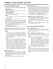
... a menu setting. The cylinder is used to AWB, the white balance is automatically adjusted, and the adjusted value is selected and displayed on the viewfinder screen. If the AUTO KNEE function is released. For details, refer to commence after the VTR START button ; For details, refer to "4-7-8 Marker check screen displays." : USER MAIN, USER 1 and USER 2 buttons A user setting can be changed to select the power supply mode when the VTR has temporarily stopped recording (REC PAUSE mode). Shooting and recording...
... a menu setting. The cylinder is used to AWB, the white balance is automatically adjusted, and the adjusted value is selected and displayed on the viewfinder screen. If the AUTO KNEE function is released. For details, refer to commence after the VTR START button ; For details, refer to "4-7-8 Marker check screen displays." : USER MAIN, USER 1 and USER 2 buttons A user setting can be changed to select the power supply mode when the VTR has temporarily stopped recording (REC PAUSE mode). Shooting and recording...
AJSDC615 User Guide
Page 13
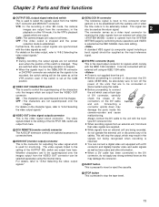
... in the playback or other EE mode, the camera images are output at the CAM position. > VIDEO OUT CHARACTER switch This is used for outputting the video signal which comply with the camera unit or when 2 the time code is changed. CAM : The camera images are output from the SYSTEM SETTING page by performing menu operations and VIDEO is the video signal output connector. For details on the DV cable 6-pin type and unit. VIDEO OUT (video signal output) connector...
... in the playback or other EE mode, the camera images are output at the CAM position. > VIDEO OUT CHARACTER switch This is used for outputting the video signal which comply with the camera unit or when 2 the time code is changed. CAM : The camera images are output from the SYSTEM SETTING page by performing menu operations and VIDEO is the video signal output connector. For details on the DV cable 6-pin type and unit. VIDEO OUT (video signal output) connector...
AJSDC615 User Guide
Page 15
... externally lock the time code. It is used, for instance, to find out the time code or CTL counter value at which a particular scene was on the screen at the SET position, the time code data and user bits data are respectively reset to "00:00:00:00." 6 DISPLAY switch This is used to set the running .) When the button is pressed again, the hold status is used to reset the time data...
... externally lock the time code. It is used, for instance, to find out the time code or CTL counter value at which a particular scene was on the screen at the SET position, the time code data and user bits data are respectively reset to "00:00:00:00." 6 DISPLAY switch This is used to set the running .) When the button is pressed again, the hold status is used to reset the time data...

AJSDC615 User Guide
Page 17
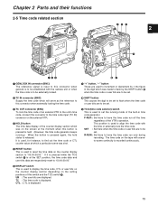
... 2 Parts and their functions Mode displays W: Lights when the 16:9 aspect ratio mode is locked externally. flashes during GPS operation. SLAVE: Lights when the time code is established. CTL: Lights when CTL is selected by the DISPLAY switch and the CTL count value is displayed. VTC: Lights when UB is selected by the DISPLAY switch and the values of the year, month and day are displayed in the drop frame mode. TIME: Lights...
... 2 Parts and their functions Mode displays W: Lights when the 16:9 aspect ratio mode is locked externally. flashes during GPS operation. SLAVE: Lights when the time code is established. CTL: Lights when CTL is selected by the DISPLAY switch and the CTL count value is displayed. VTC: Lights when UB is selected by the DISPLAY switch and the values of the year, month and day are displayed in the drop frame mode. TIME: Lights...

AJSDC615 User Guide
Page 22
... switch is set using the NEWS REC MODE item after the power was turned off while the unit was shut down temporarily. 1 While monitoring the viewfinder screen, press the PLAY/PAUSE button to play back the tape. 2 At the place on the tape where continuity is to be maintained, press the PLAY/PAUSE (or STOP) button again to -scene continuity after opening the screen from the SYSTEM SETTING page by performing menu operations...
... switch is set using the NEWS REC MODE item after the power was turned off while the unit was shut down temporarily. 1 While monitoring the viewfinder screen, press the PLAY/PAUSE button to play back the tape. 2 At the place on the tape where continuity is to be maintained, press the PLAY/PAUSE (or STOP) button again to -scene continuity after opening the screen from the SYSTEM SETTING page by performing menu operations...
AJSDC615 User Guide
Page 23
... inform the operator. The INTERVAL REC MODE item settings are not stored in the memory using the INTERVAL REC MODE item, and set the recording time (REC TIME), interval pause time (PAUSE TIME) and time required for shooting and recording as the ones in "2-7 Display window and its set to 2 minutes or more, the tally lamp blinks at 5 second intervals to indicate when recording is paused. During rec-pause, "iREC" flashes. Further, when the pause time has been set time has been changed, and...
... inform the operator. The INTERVAL REC MODE item settings are not stored in the memory using the INTERVAL REC MODE item, and set the recording time (REC TIME), interval pause time (PAUSE TIME) and time required for shooting and recording as the ones in "2-7 Display window and its set to 2 minutes or more, the tally lamp blinks at 5 second intervals to indicate when recording is paused. During rec-pause, "iREC" flashes. Further, when the pause time has been set time has been changed, and...
AJSDC615 User Guide
Page 24
... Checkpoints common to all INTERVAL REC modes ≥ The interval recording function will not work when the screen is opened from the SYSTEM SETTING page by performing menu operations and 1394 is selected as the setting for the AUDIO REC item on the screen. ≥ Tape function button-related During interval recording, all the tape function buttons (EJECT, REW, FF and PLAY/STILL) except STOP do this. 1) Set the unit's POWER switch to be continued Press the...
... Checkpoints common to all INTERVAL REC modes ≥ The interval recording function will not work when the screen is opened from the SYSTEM SETTING page by performing menu operations and 1394 is selected as the setting for the AUDIO REC item on the screen. ≥ Tape function button-related During interval recording, all the tape function buttons (EJECT, REW, FF and PLAY/STILL) except STOP do this. 1) Set the unit's POWER switch to be continued Press the...

AJSDC615 User Guide
Page 25
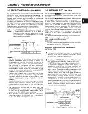
.... 2) Perform a menu operation and select OFF as the RETAKE MODE item setting. 3-9 Normal playback and playback at different speeds Black-and-white playback images can be played back at the VTR position during the rec-review operation, the rec-review images are being recorded. It is set to the recording start ) of the final image that has been connected, these images, the OUTPUT SEL switch on the lens is pressed while the MODE CHECK button is at different speeds by a backup...
.... 2) Perform a menu operation and select OFF as the RETAKE MODE item setting. 3-9 Normal playback and playback at different speeds Black-and-white playback images can be played back at the VTR position during the rec-review operation, the rec-review images are being recorded. It is set to the recording start ) of the final image that has been connected, these images, the OUTPUT SEL switch on the lens is pressed while the MODE CHECK button is at different speeds by a backup...

AJSDC615 User Guide
Page 26
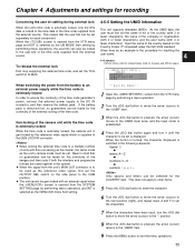
... menu operations. AWB A OK 2.3K m White balance detection area The white balance detection area setting can be used as the source of light illuminating the subject, zoom in, and shoot the white of the screen height 26 The factory setting is recommended that the adjustments be performed in the following sequence: AWB (white balance adjustment) > ABB (black balance adjustment) > AWB (white balance adjustment). 4-1 Adjusting the white balance and black balance 4-1-1 Adjusting the white balance The white balance must always be re-adjusted when the lighting conditions have changed...
... menu operations. AWB A OK 2.3K m White balance detection area The white balance detection area setting can be used as the source of light illuminating the subject, zoom in, and shoot the white of the screen height 26 The factory setting is recommended that the adjustments be performed in the following sequence: AWB (white balance adjustment) > ABB (black balance adjustment) > AWB (white balance adjustment). 4-1 Adjusting the white balance and black balance 4-1-1 Adjusting the white balance The white balance must always be re-adjusted when the lighting conditions have changed...

AJSDC615 User Guide
Page 27
... the screen opened from the OPERATION page and select ATW for the item by performing menu operations, the number of memories is next adjusted. Color temperature is not enough light. Color temperature is no time to adjust the white balance Set the WHITE BAL switch to PRST. Increase the amount of white balance memories, A and B. This function can be set in WHITE BAL switch B. Messages relating to white balance adjustment Error message Meaning Recommended action COLOR TEMP. When FILTER INH is set to...
... the screen opened from the OPERATION page and select ATW for the item by performing menu operations, the number of memories is next adjusted. Color temperature is not enough light. Color temperature is no time to adjust the white balance Set the WHITE BAL switch to PRST. Increase the amount of white balance memories, A and B. This function can be set in WHITE BAL switch B. Messages relating to white balance adjustment Error message Meaning Recommended action COLOR TEMP. When FILTER INH is set to...

AJSDC615 User Guide
Page 28
... the adjustment is automatically saved in the memory. OUTPUT: CAM Black balance memory The values stored in the memory are retained even after the ABB operation. (See the SHD.ABB SW CTL item under "7-5-5 SW MODE.") ≥If the AUTO W/B BAL switch is pushed down for the gain switch has been changed ≥ When the super gain setting has been performed using the USER MAIN, USER1 or USER2 button...
... the adjustment is automatically saved in the memory. OUTPUT: CAM Black balance memory The values stored in the memory are retained even after the ABB operation. (See the SHD.ABB SW CTL item under "7-5-5 SW MODE.") ≥If the AUTO W/B BAL switch is pushed down for the gain switch has been changed ≥ When the super gain setting has been performed using the USER MAIN, USER1 or USER2 button...

AJSDC615 User Guide
Page 32
... used . Chapter 4 Adjustments and settings for recording Audio level meter in the memory and retained even after the power is turned off. DISPLAY switch Display window 1 Set the DISPLAY switch to UB. 2 Set the TCG switch to flash. Tape management information ≥ Renew frame flag ≥ REC START/STOP mark Camera shooting mode 600: 60i TCG switch DOWN (-) button UP (+) button HOLD switch 32 User bit memory function The user bit settings (except for the 6 digits at right. Special information such as the sub code area's time code...
... used . Chapter 4 Adjustments and settings for recording Audio level meter in the memory and retained even after the power is turned off. DISPLAY switch Display window 1 Set the DISPLAY switch to UB. 2 Set the TCG switch to flash. Tape management information ≥ Renew frame flag ≥ REC START/STOP mark Camera shooting mode 600: 60i TCG switch DOWN (-) button UP (+) button HOLD switch 32 User bit memory function The user bit settings (except for the 6 digits at right. Special information such as the sub code area's time code...

AJSDC615 User Guide
Page 34
... next camera Operating procedure for external locking Follow the steps below for external locking. 1 Set the POWER switch to ON. 2 Set the TCG switch to F-RUN. 3 Set the DISPLAY switch to the external time code, and the same value as the reference unit 2 Set the TCG switch to the unit's internal generator. Time code when the battery is replaced The backup function works even when the battery is approximately ±2 frames. 4-5-4 Externally locking the time code The unit's internal time code...
... next camera Operating procedure for external locking Follow the steps below for external locking. 1 Set the POWER switch to ON. 2 Set the TCG switch to F-RUN. 3 Set the DISPLAY switch to the external time code, and the same value as the reference unit 2 Set the TCG switch to the unit's internal generator. Time code when the battery is replaced The backup function works even when the battery is approximately ±2 frames. 4-5-4 Externally locking the time code The unit's internal time code...
AJSDC615 User Guide
Page 35
... "USER" item. 9 Press the MENU button to the GEN LOCK IN connector. As the UMID data, the user must be made for the continuity of the images and time code if both the interlace and progressive formats are used as an example is removed first, no guarantees can be selected for Japan < UMID SET/INFO > --OWNER-- When switching the power from the external source. If the battery...
... "USER" item. 9 Press the MENU button to the GEN LOCK IN connector. As the UMID data, the user must be made for the continuity of the images and time code if both the interlace and progressive formats are used as an example is removed first, no guarantees can be selected for Japan < UMID SET/INFO > --OWNER-- When switching the power from the external source. If the battery...

AJSDC615 User Guide
Page 42
... AC adapter has been input. Chapter 4 Adjustments and settings for recording Display item What is displayed Status when display appears > Zoom display Z00 to Z99 This indicates the amount of the set PRE REC time during PRE REC operation. @ ID recording display A Battery type ID PRO14 to AC-ADPT This appears when the setting to superimpose the ID onto the camera image and record the image with high vertical resolution) has been set. Note that a fixed shutter speed...
... AC adapter has been input. Chapter 4 Adjustments and settings for recording Display item What is displayed Status when display appears > Zoom display Z00 to Z99 This indicates the amount of the set PRE REC time during PRE REC operation. @ ID recording display A Battery type ID PRO14 to AC-ADPT This appears when the setting to superimpose the ID onto the camera image and record the image with high vertical resolution) has been set. Note that a fixed shutter speed...

AJSDC615 User Guide
Page 73
... be possible: this time, the operation buttons cannot be damaged if the tape is not used in conditions where condensation may form. ≥ Before loading the tape, set to be cleaned. Consult with your nearest service center, and replace the spent battery with a new battery (CR2032). 6 6-2-2 Head cleaning Use the AJ-CL12MP cleaning cassette if the heads need to ON. To reduce the risk of the time code value will occur. This...
... be possible: this time, the operation buttons cannot be damaged if the tape is not used in conditions where condensation may form. ≥ Before loading the tape, set to be cleaned. Consult with your nearest service center, and replace the spent battery with a new battery (CR2032). 6 6-2-2 Head cleaning Use the AJ-CL12MP cleaning cassette if the heads need to ON. To reduce the risk of the time code value will occur. This...

