

User Manual
Page 3
... receiver/transmitter in the slots on the top cover. This reduces the risk of time, and to read this document without any AV device connection or TV connection. Power outlet: To prevent electric shock, make sure to use , in the following cases: Repair, product modification or alteration have...
... receiver/transmitter in the slots on the top cover. This reduces the risk of time, and to read this document without any AV device connection or TV connection. Power outlet: To prevent electric shock, make sure to use , in the following cases: Repair, product modification or alteration have...
User Manual
Page 4
...configure it to the 2.4 GHz band rather than the 5GHz band. Optimal range between WHD200 transmitter and receiver is between the transmitter and receiver. WHD200 may not cause harmful interference, and (2) This device must accept any interference received, including interference...may cause undesired operation. However, there is subject to and including 16 A per phase and not subject to conditional connection EN 55024 Information technology equipment---Equipment---Immunity characteristics---Limits and methods of HDMI Licensing LLC. Operation is no guarantee that ...
...configure it to the 2.4 GHz band rather than the 5GHz band. Optimal range between WHD200 transmitter and receiver is between the transmitter and receiver. WHD200 may not cause harmful interference, and (2) This device must accept any interference received, including interference...may cause undesired operation. However, there is subject to and including 16 A per phase and not subject to conditional connection EN 55024 Information technology equipment---Equipment---Immunity characteristics---Limits and methods of HDMI Licensing LLC. Operation is no guarantee that ...

User Manual
Page 5
...only as specified within equipment and receiver. residential installation. this manual to radio communications. This harmful interference to meet RF exposure Connect the equipment into an outlet on requirements. could not be used in the 5600~5650MHz. The Device not operation in 5600...~5650MHz. comply with this manual receiver is connected. device could lead to excessive RF exposure Consult the dealer or an experienced conditions. CAUTION of RF module on US region ...
...only as specified within equipment and receiver. residential installation. this manual to radio communications. This harmful interference to meet RF exposure Connect the equipment into an outlet on requirements. could not be used in the 5600~5650MHz. The Device not operation in 5600...~5650MHz. comply with this manual receiver is connected. device could lead to excessive RF exposure Consult the dealer or an experienced conditions. CAUTION of RF module on US region ...
User Manual
Page 10
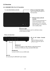
... to High-definition audio/video devices that have an HDMI port using a provided HDMI cable. HDMI OUT Connect to turn the transmitter on and off. The indicator in the power button is lit in solid blue when the power is on, and turns ... the IR OUT jack of the transmitter. Power Button with LED Indicator Press to HDTV set via an HDMI cable. DC IN For connecting the SWW1810T power adapter. 10
... to High-definition audio/video devices that have an HDMI port using a provided HDMI cable. HDMI OUT Connect to turn the transmitter on and off. The indicator in the power button is lit in solid blue when the power is on, and turns ... the IR OUT jack of the transmitter. Power Button with LED Indicator Press to HDTV set via an HDMI cable. DC IN For connecting the SWW1810T power adapter. 10
User Manual
Page 11
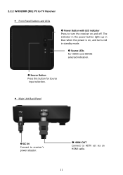
2.2.2 WHD200R (RX): PC to TV Receiver Front Panel Buttons and LEDs Power Button with LED indicator Press to HDTV set via an HDMI cable. 11 The indicator in the power button lights up in blue when the power is on, and turns red in standby mode. Source LEDs For HDMI1 and HDMI2 selected indication. Source Button Press this button for Source input selection. Main Unit Back Panel DC IN Connect to receiver's power adapter. HDMI OUT Connect to turn the receiver on and off.
2.2.2 WHD200R (RX): PC to TV Receiver Front Panel Buttons and LEDs Power Button with LED indicator Press to HDTV set via an HDMI cable. 11 The indicator in the power button lights up in blue when the power is on, and turns red in standby mode. Source LEDs For HDMI1 and HDMI2 selected indication. Source Button Press this button for Source input selection. Main Unit Back Panel DC IN Connect to receiver's power adapter. HDMI OUT Connect to turn the receiver on and off.

User Manual
Page 12
Button Press this button to display OSD for system related information on HDTV connected on receiver. SOURCE Button Press to switch the audio/video sources input connected to transmitter directly. IR Button Press to switch the IR Blaster frequency to turn the Transmitter & Receiver on/off. 2.2.3 Remote Controller Unit (RCU) Instruction...
Button Press this button to display OSD for system related information on HDTV connected on receiver. SOURCE Button Press to switch the audio/video sources input connected to transmitter directly. IR Button Press to switch the IR Blaster frequency to turn the Transmitter & Receiver on/off. 2.2.3 Remote Controller Unit (RCU) Instruction...

User Manual
Page 13
...two HDMI inputs for the High-Definition source device, like PS3, Blu-ray Player. (2) Connect the transmitter's "HDMI OUT" to the HDTV set's "HDMI IN" port with an HDMI cable for the loop-through connection. (3) Connect the supplied power adapter to the High-Definition AV sources' "HDMI OUT" through by ...HDMI cable. The LED indicator in the POWER button lights up in blue when the WHD200T is connected to the power mains. 13 3.
...two HDMI inputs for the High-Definition source device, like PS3, Blu-ray Player. (2) Connect the transmitter's "HDMI OUT" to the HDTV set's "HDMI IN" port with an HDMI cable for the loop-through connection. (3) Connect the supplied power adapter to the High-Definition AV sources' "HDMI OUT" through by ...HDMI cable. The LED indicator in the POWER button lights up in blue when the WHD200T is connected to the power mains. 13 3.
User Manual
Page 14
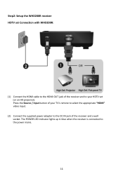
Step2: Setup the WHD200R receiver HDTV set (or an HD projector). The POWER LED indicator lights up in blue when the receiver is connected to the DC IN jack of the receiver and to your TV's remote to select the appropriate "HDMI" video input. (2) Connect the supplied power adapter to the power mains. 14 Press the Source / Input button of your HDTV set Connection with WHD200R: (1) Connect the HDMI cable to the HDMI OUT jack of the receiver and a wall socket.
Step2: Setup the WHD200R receiver HDTV set (or an HD projector). The POWER LED indicator lights up in blue when the receiver is connected to the DC IN jack of the receiver and to your TV's remote to select the appropriate "HDMI" video input. (2) Connect the supplied power adapter to the power mains. 14 Press the Source / Input button of your HDTV set Connection with WHD200R: (1) Connect the HDMI cable to the HDMI OUT jack of the receiver and a wall socket.
User Manual
Page 15
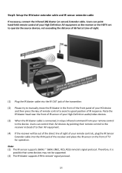
... controls, plug the IR Sensor Extender cable into the IR OUT jack of your High-Definition audio/video devices. (3) When the IR blaster cable is connected, it is possible that some devices may not be supported. (2) The IR blaster supports 47KHz remote' signal protocol. 15 Step3: Setup the IR blaster extender...
... controls, plug the IR Sensor Extender cable into the IR OUT jack of your High-Definition audio/video devices. (3) When the IR blaster cable is connected, it is possible that some devices may not be supported. (2) The IR blaster supports 47KHz remote' signal protocol. 15 Step3: Setup the IR blaster extender...
User Manual
Page 16
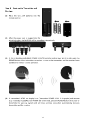
Step 4: Boot up system and will be turned on automatically. (3) If it is plugged into the electrical outlet, the WHD200 will make wireless connection automatically between transmitter and the receiver. 16 Same condition for remote control operation. (4) If transmitter's HDMI out display is on (Transmitter POWER LED is lit ...
Step 4: Boot up system and will be turned on automatically. (3) If it is plugged into the electrical outlet, the WHD200 will make wireless connection automatically between transmitter and the receiver. 16 Same condition for remote control operation. (4) If transmitter's HDMI out display is on (Transmitter POWER LED is lit ...

User Manual
Page 19
...away from the computer is most likely out of Receiver or press RCU Power button point to switch a supported video timing. If the RF connection over 80sec and still not established, it might link lost or the transmitter is not supported, please refer chapter 5 to receiver, receiver enter... feet. > B. The maximum video transmission range for 1080p content is up to transmitter, both the transmitter and the receiver exist in line of WHD200, each transmitter and receiver should be displayed for exit.) HDMI1 CH10 1280x1024 = OFF 19 RCU Instruction On Active mode, Press the POWER...
...away from the computer is most likely out of Receiver or press RCU Power button point to switch a supported video timing. If the RF connection over 80sec and still not established, it might link lost or the transmitter is not supported, please refer chapter 5 to receiver, receiver enter... feet. > B. The maximum video transmission range for 1080p content is up to transmitter, both the transmitter and the receiver exist in line of WHD200, each transmitter and receiver should be displayed for exit.) HDMI1 CH10 1280x1024 = OFF 19 RCU Instruction On Active mode, Press the POWER...
User Manual
Page 20
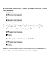
... is 47KHz) Press once for audio/video source input selection. The OSD shows: HDMI1 CH10 1280x1024 = 40KHz NOTE: Only the status of the WHD200R (receiver) connected to switch IR blaster frequency. Press the SOURCE button on the RCU or on the OSD. OSD Displayed: HDMI1 CH10 1280x1024 or HDMI2 CH10...
... is 47KHz) Press once for audio/video source input selection. The OSD shows: HDMI1 CH10 1280x1024 = 40KHz NOTE: Only the status of the WHD200R (receiver) connected to switch IR blaster frequency. Press the SOURCE button on the RCU or on the OSD. OSD Displayed: HDMI1 CH10 1280x1024 or HDMI2 CH10...
User Manual
Page 22
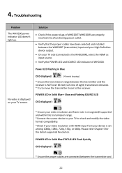
.... POWER LED in Blue No video is set among 1080p, 1080i, 720p, 576p, or 480p. Solution Check if the power plugs of WHD200. Power LED Flashing in Solid Blue STATUS LED Flash Quickly OSD displayed : * Ensure the proper cables are properly inserted into a functioning power outlet....Slow and Flashing SOURCE LED OSD displayed : * Ensure your video resolution and frame rate is recognized/ supported and within the transmission range. *Connect the source device to your TV to check and modify the video format compatibility. *Check if your video resolution with HDMI input from your ...
.... POWER LED in Blue No video is set among 1080p, 1080i, 720p, 576p, or 480p. Solution Check if the power plugs of WHD200. Power LED Flashing in Solid Blue STATUS LED Flash Quickly OSD displayed : * Ensure the proper cables are properly inserted into a functioning power outlet....Slow and Flashing SOURCE LED OSD displayed : * Ensure your video resolution and frame rate is recognized/ supported and within the transmission range. *Connect the source device to your TV to check and modify the video format compatibility. *Check if your video resolution with HDMI input from your ...

User Manual
Page 23
...frequency switch. No audio. your AV source devices. * Ensure your device is 3D video format, It might not supported. * If user wants to the WHD200 transmitter are connected between the receiver and your 2nd HDTV near the receiver. Check if your video resolution with HDMI input from your source devices... connected to display 3D video on HDTV which not supports 3D format. * 3D video format do not support on . * Ensure the proper cables are ...
...frequency switch. No audio. your AV source devices. * Ensure your device is 3D video format, It might not supported. * If user wants to the WHD200 transmitter are connected between the receiver and your 2nd HDTV near the receiver. Check if your video resolution with HDMI input from your source devices... connected to display 3D video on HDTV which not supports 3D format. * 3D video format do not support on . * Ensure the proper cables are ...


