
User Manual
Page 2
... AND RECEIVER 16 STEP 5: MOUNTING THE WHD200 TO THE WALL 21 4. AUDIO BIT RATE SUPPORT 26 7. Table of Contents TABLE OF CONTENTS...1 1. TROUBLESHOOTING 21 5. INTRODUCTION...8 2.1 PACKING CONTENT...8 2.2 OVERVIEW ...8 2.2 OVERVIEW ...8 2.2.1 WHD200T (TX): PC TO TV TRANSMITTER 10 2.2.2 WHD200R (RX): PC TO TV RECEIVER 10 2.2.2 WHD200R (RX): PC TO TV RECEIVER 11 2.2.3 REMOTE CONTROLLER UNIT (RCU) INSTRUCTION 12 3. PRODUCT SPECIFICATION 27 1
... AND RECEIVER 16 STEP 5: MOUNTING THE WHD200 TO THE WALL 21 4. AUDIO BIT RATE SUPPORT 26 7. Table of Contents TABLE OF CONTENTS...1 1. TROUBLESHOOTING 21 5. INTRODUCTION...8 2.1 PACKING CONTENT...8 2.2 OVERVIEW ...8 2.2 OVERVIEW ...8 2.2.1 WHD200T (TX): PC TO TV TRANSMITTER 10 2.2.2 WHD200R (RX): PC TO TV RECEIVER 10 2.2.2 WHD200R (RX): PC TO TV RECEIVER 11 2.2.3 REMOTE CONTROLLER UNIT (RCU) INSTRUCTION 12 3. PRODUCT SPECIFICATION 27 1

User Manual
Page 3
... heavy object on the case or remove the cover. Always disconnect the power cord from direct sunlight or any work is left unattended for intended use the appropriate AC adapters as vases, should not be switched off before using your Full HD Video wireless kit. Blocking the air flow could result in accordance with liquids, such as power supply to , lightning, water, fire, or...
... heavy object on the case or remove the cover. Always disconnect the power cord from direct sunlight or any work is left unattended for intended use the appropriate AC adapters as vases, should not be switched off before using your Full HD Video wireless kit. Blocking the air flow could result in accordance with liquids, such as power supply to , lightning, water, fire, or...
User Manual
Page 4
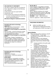
... undesirable effect on the operation result. Use of this product nearby an aircraft or medical facility. Part 1: Common technical requirements TRADEMARK INFORMATION HDMI, the HDMI Logo and High-Definition Multimedia Interface are trademarks of sight. 3 etc,). Product installed in the walls made of voltage changes, voltage fluctuations and flicker in public low-voltage supply systems, for radio equipment...
... undesirable effect on the operation result. Use of this product nearby an aircraft or medical facility. Part 1: Common technical requirements TRADEMARK INFORMATION HDMI, the HDMI Logo and High-Definition Multimedia Interface are trademarks of sight. 3 etc,). Product installed in the walls made of voltage changes, voltage fluctuations and flicker in public low-voltage supply systems, for radio equipment...

User Manual
Page 5
...users and installers must be used with provided ID displayed on requirements. this document supplied to an OEM or integrator, but should be operated and used in the 5600~5650MHz. The Device not operation in accordance with a locally approved access point. 4 comply with antenna installation instructions and transmitter operating conditions for other antenna or transmitter. However, there is connected. Use... be installed to Part 15 of this manual receiver is no Ad-hoc capability for a Class B digital device, pursuant to provide a separation distance of ...
...users and installers must be used with provided ID displayed on requirements. this document supplied to an OEM or integrator, but should be operated and used in the 5600~5650MHz. The Device not operation in accordance with a locally approved access point. 4 comply with antenna installation instructions and transmitter operating conditions for other antenna or transmitter. However, there is connected. Use... be installed to Part 15 of this manual receiver is no Ad-hoc capability for a Class B digital device, pursuant to provide a separation distance of ...
User Manual
Page 6
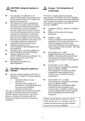
... compatibility and Radio Spectrum Matters (ERM); End-users and installers must be used for this System in the US Europe - CAUTION: Using this transmitter must accept any other relevant provisions of Directive 1995/5/EC. 5 Part 17: Specific conditions for radio equipment and services; This device must be co-located or operating in 5600~5650MHz. This device could void the...
... compatibility and Radio Spectrum Matters (ERM); End-users and installers must be used for this System in the US Europe - CAUTION: Using this transmitter must accept any other relevant provisions of Directive 1995/5/EC. 5 Part 17: Specific conditions for radio equipment and services; This device must be co-located or operating in 5600~5650MHz. This device could void the...

User Manual
Page 7
...LAN devices. In these radars could cause interference and/or damage to co-channel mobile satellite systems; (ii) high-power radars are allocated as primary users (i.e. IMPORTANT NOTE: (IC: 9078A-ZRF31200) French translation: Radiation Exposure Statement: This equipment complies with IC radiation exposure limits set...fonctionnement indésirable. (i) the device for operation in the band 5150-5250 MHz is only for indoor use to reduce the potential for example certain laptop configurations or co-location with minimum distance 20cm between the radiator & your body. This...
...LAN devices. In these radars could cause interference and/or damage to co-channel mobile satellite systems; (ii) high-power radars are allocated as primary users (i.e. IMPORTANT NOTE: (IC: 9078A-ZRF31200) French translation: Radiation Exposure Statement: This equipment complies with IC radiation exposure limits set...fonctionnement indésirable. (i) the device for operation in the band 5150-5250 MHz is only for indoor use to reduce the potential for example certain laptop configurations or co-location with minimum distance 20cm between the radiator & your body. This...
User Manual
Page 9
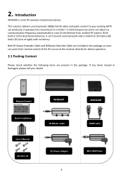
... 1080p full HD video and audio content to 20 meters (66 feet) LOS (Line of interference from another RF system. Introduction WHD200 is a Full HD wireless transmission device. It operates the transmission in case of sight) with no latency. Remote Control Quick Installation User's Manual Anchors x2 WHD200T IR Blaster cable DC Power Adapter 8 WHD200R HDMI cable Mini USB Power Both IR Sensor Extender Cable and IR Blaster...
... 1080p full HD video and audio content to 20 meters (66 feet) LOS (Line of interference from another RF system. Introduction WHD200 is a Full HD wireless transmission device. It operates the transmission in case of sight) with no latency. Remote Control Quick Installation User's Manual Anchors x2 WHD200T IR Blaster cable DC Power Adapter 8 WHD200R HDMI cable Mini USB Power Both IR Sensor Extender Cable and IR Blaster...
User Manual
Page 10
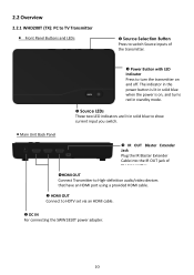
... the transmitter. Power Button with LED Indicator Press to HDTV set via an HDMI cable. DC IN For connecting the SWW1810T power adapter. 10 2.2 Overview 2.2.1 WHD200T (TX): PC to TV Transmitter Front Panel Buttons and LEDs Source Selection Button Press to switch Source inputs of the transmitter. HDMI OUT Connect Transmitter to High-definition audio/video devices that have an HDMI port using a provided HDMI cable. HDMI OUT Connect to turn the transmitter on and...
... the transmitter. Power Button with LED Indicator Press to HDTV set via an HDMI cable. DC IN For connecting the SWW1810T power adapter. 10 2.2 Overview 2.2.1 WHD200T (TX): PC to TV Transmitter Front Panel Buttons and LEDs Source Selection Button Press to switch Source inputs of the transmitter. HDMI OUT Connect Transmitter to High-definition audio/video devices that have an HDMI port using a provided HDMI cable. HDMI OUT Connect to turn the transmitter on and...
User Manual
Page 11
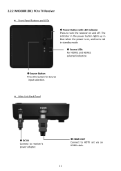
The indicator in the power button lights up in standby mode. Source LEDs For HDMI1 and HDMI2 selected indication. Source Button Press this button for Source input selection. Main Unit Back Panel DC IN Connect to receiver's power adapter. HDMI OUT Connect to turn the receiver on , and turns red in blue when the power is on and off. 2.2.2 WHD200R (RX): PC to TV Receiver Front Panel Buttons and LEDs Power Button with LED indicator Press to HDTV set via an HDMI cable. 11
The indicator in the power button lights up in standby mode. Source LEDs For HDMI1 and HDMI2 selected indication. Source Button Press this button for Source input selection. Main Unit Back Panel DC IN Connect to receiver's power adapter. HDMI OUT Connect to turn the receiver on , and turns red in blue when the power is on and off. 2.2.2 WHD200R (RX): PC to TV Receiver Front Panel Buttons and LEDs Power Button with LED indicator Press to HDTV set via an HDMI cable. 11

User Manual
Page 12
.... Button Press this button to display OSD for system related information on HDTV connected on /off. When both of TX & RX Power LEDs are red, press Power button either TX OR RX, it can switch IR Blaster frequency 47K to 56K to meet Source device's requirement. 2.2.3 Remote Controller Unit (RCU) Instruction POWER Button Press to turn the Transmitter & Receiver on receiver. SOURCE Button Press to switch the audio/video sources input connected to...
.... Button Press this button to display OSD for system related information on HDTV connected on /off. When both of TX & RX Power LEDs are red, press Power button either TX OR RX, it can switch IR Blaster frequency 47K to 56K to meet Source device's requirement. 2.2.3 Remote Controller Unit (RCU) Instruction POWER Button Press to turn the Transmitter & Receiver on receiver. SOURCE Button Press to switch the audio/video sources input connected to...

User Manual
Page 13
... AV sources' "HDMI OUT" through connection. (3) Connect the supplied power adapter to the DC IN jack of the transmitter and a wall socket. The transmitter has two HDMI inputs for the High-Definition source device, like PS3, Blu-ray Player. (2) Connect the transmitter's "HDMI OUT" to the power mains. 13 3. The LED indicator in the POWER button lights up in blue when the WHD200T is connected to the HDTV set's "HDMI IN" port with an HDMI cable...
... AV sources' "HDMI OUT" through connection. (3) Connect the supplied power adapter to the DC IN jack of the transmitter and a wall socket. The transmitter has two HDMI inputs for the High-Definition source device, like PS3, Blu-ray Player. (2) Connect the transmitter's "HDMI OUT" to the power mains. 13 3. The LED indicator in the POWER button lights up in blue when the WHD200T is connected to the HDTV set's "HDMI IN" port with an HDMI cable...
User Manual
Page 14
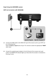
The POWER LED indicator lights up in blue when the receiver is connected to the DC IN jack of the receiver and a wall socket. Step2: Setup the WHD200R receiver HDTV set (or an HD projector). Press the Source / Input button of your HDTV set Connection with WHD200R: (1) Connect the HDMI cable to the HDMI OUT jack of the receiver and to your TV's remote to select the appropriate "HDMI" video input. (2) Connect the supplied power adapter to the power mains. 14
The POWER LED indicator lights up in blue when the receiver is connected to the DC IN jack of the receiver and a wall socket. Step2: Setup the WHD200R receiver HDTV set (or an HD projector). Press the Source / Input button of your HDTV set Connection with WHD200R: (1) Connect the HDMI cable to the HDMI OUT jack of the receiver and to your TV's remote to select the appropriate "HDMI" video input. (2) Connect the supplied power adapter to the power mains. 14
User Manual
Page 15
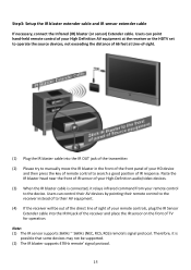
... cable If necessary, connect the Infrared (IR) blaster (or sensor) Extender cable. Users can control their AV devices by pointing their AV equipment. (4) If the receiver will be supported. (2) The IR blaster supports 47KHz remote' signal protocol. 15 Users can point hand-held remote control of your High Definition AV equipment at the receiver or the HDTV set to operate the source devices, not exceeding the distance...
... cable If necessary, connect the Infrared (IR) blaster (or sensor) Extender cable. Users can control their AV devices by pointing their AV equipment. (4) If the receiver will be supported. (2) The IR blaster supports 47KHz remote' signal protocol. 15 Users can point hand-held remote control of your High Definition AV equipment at the receiver or the HDTV set to operate the source devices, not exceeding the distance...

User Manual
Page 17
(5) During the warm-up successfully. (6) Ensure your device. 17 It will blink in blue until the signal link between the WHD200T and the WHD200R is already powered on. (7) Press the Source button on the RCU or on the top of receiver / transmitter for system boot up , the POWER LED will take 15 ~ 20 seconds for Source input switch until you see the video being broadcasted from your TV set or projector is in "HDMI input" mode, and is established.
(5) During the warm-up successfully. (6) Ensure your device. 17 It will blink in blue until the signal link between the WHD200T and the WHD200R is already powered on. (7) Press the Source button on the RCU or on the top of receiver / transmitter for system boot up , the POWER LED will take 15 ~ 20 seconds for Source input switch until you see the video being broadcasted from your TV set or projector is in "HDMI input" mode, and is established.

User Manual
Page 18
... / Mode Status Description Power LED Status LED (on RX) (on RX) OSD Display (on RX) Standby For power saving mode. Looping display these two OSD 18 Searching available channels Continuing search available channels If system can't establish link over 80s after initialization. (Note A & D) Blinking Blue Blinking Wireless linked Mode No input from selected source (Note B) Video format not recognized (Note C) Static Blue Static Blue Blinking (Quickly) Blinking (Slowly) Video format is normal, the POWER LED and...
... / Mode Status Description Power LED Status LED (on RX) (on RX) OSD Display (on RX) Standby For power saving mode. Looping display these two OSD 18 Searching available channels Continuing search available channels If system can't establish link over 80s after initialization. (Note A & D) Blinking Blue Blinking Wireless linked Mode No input from selected source (Note B) Video format not recognized (Note C) Static Blue Static Blue Blinking (Quickly) Blinking (Slowly) Video format is normal, the POWER LED and...

User Manual
Page 19
... suggested the distance between your HDTV set with the transmitter and the receiver. The maximum video transmission range for 1080p content is up to receiver, receiver enter Standby mode and transmitter's HDMI out is 6.5 feet minimum. (9) On Screen Display (OSD) vs. If you have to switch a supported video timing. C. OSD Displayed: (Display 3secs and then enter Standby mode.) ON On Active mode, Press the POWER button on the...
... suggested the distance between your HDTV set with the transmitter and the receiver. The maximum video transmission range for 1080p content is up to receiver, receiver enter Standby mode and transmitter's HDMI out is 6.5 feet minimum. (9) On Screen Display (OSD) vs. If you have to switch a supported video timing. C. OSD Displayed: (Display 3secs and then enter Standby mode.) ON On Active mode, Press the POWER button on the...
User Manual
Page 22
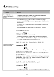
... screen. POWER LED in Blue No video is set among 1080p, 1080i, 720p, 576p, or 480p. Please refer Chapter 5 for the detail supported Resolution. Troubleshooting Problem The WHD200 power indicator LED doesn't light up. Power LED Flashing in Solid Blue + Slow and Flashing SOURCE LED OSD displayed : * Ensure your video resolution and frame rate is recognized/ supported and within the transmission range. *Connect the source device to your TV to check and modify the video format compatibility. *Check if your video resolution with HDMI input...
... screen. POWER LED in Blue No video is set among 1080p, 1080i, 720p, 576p, or 480p. Please refer Chapter 5 for the detail supported Resolution. Troubleshooting Problem The WHD200 power indicator LED doesn't light up. Power LED Flashing in Solid Blue + Slow and Flashing SOURCE LED OSD displayed : * Ensure your video resolution and frame rate is recognized/ supported and within the transmission range. *Connect the source device to your TV to check and modify the video format compatibility. *Check if your video resolution with HDMI input...

User Manual
Page 23
... setup. Please refer to the WHD200 transmitter are powered on. * Ensure the proper cables are connected between the receiver and your 2nd HDTV near the receiver. Check if your video resolution with HDMI input from your HD AV device WHD200 can 't control Source device. Check your device is less than 66 feet (LOS). If user wants to display 3D video on HDTV which supported 3D video, please turn...
... setup. Please refer to the WHD200 transmitter are powered on. * Ensure the proper cables are connected between the receiver and your 2nd HDTV near the receiver. Check if your video resolution with HDMI input from your HD AV device WHD200 can 't control Source device. Check your device is less than 66 feet (LOS). If user wants to display 3D video on HDTV which supported 3D video, please turn...

User Manual
Page 24
...Supported Resolution If the SOURCE LED continues to blink in blue (slower than "no video displayed or the video quality suffers, it indicates that the consumer timing of your A/V source device is no signal" mode); Ensure that the video frame rate from your HD device is compliant with the standard listed below: 2D Video Format Timings Resolution Primary CEA Video Timing... 30Hz VESA Timing (DVI only) 640x480 @ 59.94 / 72.809Hz VGA 800x600 @ 60.317 / 72.188Hz SVGA 1024x768 @ 60 / 70.069Hz XGA 1280x768 @ 60 Hz WXGA 1280x1024 @ 60 Hz SXGA 1600x1200 @ 60Hz UXGA Support YES YES ...
...Supported Resolution If the SOURCE LED continues to blink in blue (slower than "no video displayed or the video quality suffers, it indicates that the consumer timing of your A/V source device is no signal" mode); Ensure that the video frame rate from your HD device is compliant with the standard listed below: 2D Video Format Timings Resolution Primary CEA Video Timing... 30Hz VESA Timing (DVI only) 640x480 @ 59.94 / 72.809Hz VGA 800x600 @ 60.317 / 72.188Hz SVGA 1024x768 @ 60 / 70.069Hz XGA 1280x768 @ 60 Hz WXGA 1280x1024 @ 60 Hz SXGA 1600x1200 @ 60Hz UXGA Support YES YES ...

User Manual
Page 27
Product Specification General Specifications Supported Video Resolutions HDMI Input Supported Audio Formats Digital Audio Transmission Distance System Latency Antenna Operating Frequencies Power Supply Operating Temperature Interfaces A/V HDMI Input Interfaces HDMI Output Control IR Sensor Signal IR Blaster Extender Interfaces IR Sensor Extender Power Interface Power Input Switches Front Power Switch Front Source Switch Power LED LEDs Source LED Signal Quality Status Dimensions (mm³) 1080p, 1080i, 720p, 576p, 480p Up to 6 Mbps AC3 and DTS The maximum video ...
Product Specification General Specifications Supported Video Resolutions HDMI Input Supported Audio Formats Digital Audio Transmission Distance System Latency Antenna Operating Frequencies Power Supply Operating Temperature Interfaces A/V HDMI Input Interfaces HDMI Output Control IR Sensor Signal IR Blaster Extender Interfaces IR Sensor Extender Power Interface Power Input Switches Front Power Switch Front Source Switch Power LED LEDs Source LED Signal Quality Status Dimensions (mm³) 1080p, 1080i, 720p, 576p, 480p Up to 6 Mbps AC3 and DTS The maximum video ...


