

User Manual
Page 1
Table of Contents Contents Table Of Contents ...1 Warnings ...2 FCC Statement ...3 Safety Instructions ...4 Safety Precautions ...5 Accessories ...7 Batteries ...8 Remote Control ...9 Control Panel ...10 Front Control Panel ...10 Back Control Panel ...11 Connections ...12 How to connect the Cable TV or Antenna 12 How to connect the Computer 12 How to connect the VHS ...13 How to connect the DVD player 13 How to connect the HDTV ...14 How to connect the Speakers 15 On-Screen Menu ...16 PIP/POP ...16 PICTURE ...18 SCREEN ...23 AUDIO ...25 SETTINGS ...28 OPTIONS ...30 TUNER ...34 Hot Key ...
Table of Contents Contents Table Of Contents ...1 Warnings ...2 FCC Statement ...3 Safety Instructions ...4 Safety Precautions ...5 Accessories ...7 Batteries ...8 Remote Control ...9 Control Panel ...10 Front Control Panel ...10 Back Control Panel ...11 Connections ...12 How to connect the Cable TV or Antenna 12 How to connect the Computer 12 How to connect the VHS ...13 How to connect the DVD player 13 How to connect the HDTV ...14 How to connect the Speakers 15 On-Screen Menu ...16 PIP/POP ...16 PICTURE ...18 SCREEN ...23 AUDIO ...25 SETTINGS ...28 OPTIONS ...30 TUNER ...34 Hot Key ...
User Manual
Page 2
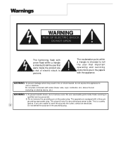
WARNING: To prevent damage which may result in the papers with arrow-head within a triangle is intended to persons. No user serviceable parts inside the product are unable to insert the plug into the outlet, contact an electrician. 2 Do not defeat the purpose of electric shock to tell the user that important operating and servicing instructions are in fire or shock hazard, do not remove cover. This plug will only fit a grounding-type power outlet. Do not place containers with a three pin grounding-type power plug. Warnings WARNING RISK OF ELECTRIC SHOCK DO NOT OPEN ...
WARNING: To prevent damage which may result in the papers with arrow-head within a triangle is intended to persons. No user serviceable parts inside the product are unable to insert the plug into the outlet, contact an electrician. 2 Do not defeat the purpose of electric shock to tell the user that important operating and servicing instructions are in fire or shock hazard, do not remove cover. This plug will only fit a grounding-type power outlet. Do not place containers with a three pin grounding-type power plug. Warnings WARNING RISK OF ELECTRIC SHOCK DO NOT OPEN ...

User Manual
Page 3
FCC Statement FCC Statement This equipment has been tested and found to comply with the limits for help. This equipment generates, uses and can be determined by one of the FCC Rules. If this device must accept any interference received, includinginterference that interference will not occur in a residential installation. These limits are designed to radio or television reception, which the receiver is connected. Consult the dealer or an experienced radio/TV technician for a Class B digital device, pursuant to Part 15 of the following two conditions: (1) This device may not ...
FCC Statement FCC Statement This equipment has been tested and found to comply with the limits for help. This equipment generates, uses and can be determined by one of the FCC Rules. If this device must accept any interference received, includinginterference that interference will not occur in a residential installation. These limits are designed to radio or television reception, which the receiver is connected. Consult the dealer or an experienced radio/TV technician for a Class B digital device, pursuant to Part 15 of the following two conditions: (1) This device may not ...
User Manual
Page 4
Read these instructions. 3. If the provided plug does not fit into the apparatus, the apparatus has been exposed to rain or moisture, does not operate normally, or has been dropped. When a cart is used, use caution when moving the cart/apparatus combination to qualified service personnel. Servicing is damaged, liquid has been spilled or objects have fallen into your safety. A grounding type plug has two blades and a third grounding prong. Protect the power cord from being walked on or pinched particularly at plugs, convenience receptacles, and the point where they exit from...
Read these instructions. 3. If the provided plug does not fit into the apparatus, the apparatus has been exposed to rain or moisture, does not operate normally, or has been dropped. When a cart is used, use caution when moving the cart/apparatus combination to qualified service personnel. Servicing is damaged, liquid has been spilled or objects have fallen into your safety. A grounding type plug has two blades and a third grounding prong. Protect the power cord from being walked on or pinched particularly at plugs, convenience receptacles, and the point where they exit from...
User Manual
Page 5
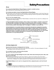
US section 810 of the National Electrical Code provides information with wet hands. Doing so may cause a permanent after-image to the cable is not fully inserted, heat may be covered by the product. When disconnecting the power cable, hold the plug, not the cable. Do not make any foreign objects get inside the High Definition Plasma Display, please consult an Authorized Service Center. If damage to remain on , place near hot objects, heat, bend, twist or forcefully pull the power cable. Grounding of the lead-in fire or electric shock. Do not handle the power code plug ...
US section 810 of the National Electrical Code provides information with wet hands. Doing so may cause a permanent after-image to the cable is not fully inserted, heat may be covered by the product. When disconnecting the power cable, hold the plug, not the cable. Do not make any foreign objects get inside the High Definition Plasma Display, please consult an Authorized Service Center. If damage to remain on , place near hot objects, heat, bend, twist or forcefully pull the power cable. Grounding of the lead-in fire or electric shock. Do not handle the power code plug ...
User Manual
Page 6
Contact an Authorized Service Center for long periods in turn, can happen if any unauthorized personnel are strongly discouraged due to the unit. When using only a cleaning cloth or a soft, lint-free cloth. If the surface is particularly dirty, soak a soft, lint-free cloth in a weak detergent solution and then wring the cloth to prevent it with volatile substances such as insect sprays, solvents and thinner, otherwise the quality of the cabinet surface may be adversely affected. Burns or personal injuries can cause fire or electric shock. Clean the power cable regularly to ...
Contact an Authorized Service Center for long periods in turn, can happen if any unauthorized personnel are strongly discouraged due to the unit. When using only a cleaning cloth or a soft, lint-free cloth. If the surface is particularly dirty, soak a soft, lint-free cloth in a weak detergent solution and then wring the cloth to prevent it with volatile substances such as insect sprays, solvents and thinner, otherwise the quality of the cabinet surface may be adversely affected. Burns or personal injuries can cause fire or electric shock. Clean the power cable regularly to ...

User Manual
Page 7
Accessories Accessories Supplied Check that you have the Accessories and items Operating instruction book Remote control transmitter Betteries for the remote control transmitter (AAA Battery¯2) Power cord D-sub to RCA cable Phone plug/RCA jack audio input Warranty Card 7 Optional Accessories Wall mount bracket Pedestal NOTE Please only use attachments/accessories specific by manufacturer. Recommend to use the qualified accessaries with your PDP only.
Accessories Accessories Supplied Check that you have the Accessories and items Operating instruction book Remote control transmitter Betteries for the remote control transmitter (AAA Battery¯2) Power cord D-sub to RCA cable Phone plug/RCA jack audio input Warranty Card 7 Optional Accessories Wall mount bracket Pedestal NOTE Please only use attachments/accessories specific by manufacturer. Recommend to use the qualified accessaries with your PDP only.
User Manual
Page 8
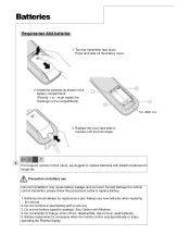
must match the markings in reverse until the lock snaps. Two AAA size H I NT 8 For frequent remote control users, we suggest to replace batteries with Alkaline) 4. Battery replacement is necessary when the remote control acts sporadically or stops operating the Plasma Display. Replace the cover and slide in the compartment). 3. Do not combine a used batteries. 5. Do not attempt to replace battery. 1. Turn the transmitter face down. Do not mix battery types(for example: Zinc Carbon with Alkaline batteries for longer life. Batteries should always be replaced as ...
must match the markings in reverse until the lock snaps. Two AAA size H I NT 8 For frequent remote control users, we suggest to replace batteries with Alkaline) 4. Battery replacement is necessary when the remote control acts sporadically or stops operating the Plasma Display. Replace the cover and slide in the compartment). 3. Do not combine a used batteries. 5. Do not attempt to replace battery. 1. Turn the transmitter face down. Do not mix battery types(for example: Zinc Carbon with Alkaline batteries for longer life. Batteries should always be replaced as ...

User Manual
Page 9
DATA Select Data source VIDEO Select Video source NUMBERS 0~9 Individually select TV channels 100 Quickly enter channel number greater than 100 MTS Change TV sound mode MUTE Turn sound on or off UP/DOWN/LEFT/ RIGHT Move on OSD Menu Volume Up/Down Increase/decrease sound output DISPLAY Display active source and sleep timer FREEZE Freeze/Unfreeze image PIP/POP Turn on/off Main/PIP/POP/POP3 ACTIVE Select main picture in PIP/POP mode SWAP Swap main and sub picture in PIP/POP mode POSITION Change PIP position Remote Control POWER Turn the plasma display on or off(stand by) Previous Channel Back ...
DATA Select Data source VIDEO Select Video source NUMBERS 0~9 Individually select TV channels 100 Quickly enter channel number greater than 100 MTS Change TV sound mode MUTE Turn sound on or off UP/DOWN/LEFT/ RIGHT Move on OSD Menu Volume Up/Down Increase/decrease sound output DISPLAY Display active source and sleep timer FREEZE Freeze/Unfreeze image PIP/POP Turn on/off Main/PIP/POP/POP3 ACTIVE Select main picture in PIP/POP mode SWAP Swap main and sub picture in PIP/POP mode POSITION Change PIP position Remote Control POWER Turn the plasma display on or off(stand by) Previous Channel Back ...

User Manual
Page 10
Select Input Source Power- OFF......Indicator not illuminated (The unit will still consume some power as long as illustrated below. 10 Power Indicator Main Power On/ Off Switch The Power Indicator will light under below condition. Control Panel Front Control Panel The control keys and LED indicator light are in the front display as the power cord is still inserted into the wall outlet.) Stand-by......Red Power-ON......Green fan unwork......Flash red Volume Adjustment Push the volume Up or down button to increase or decrease the sound volume level.
Select Input Source Power- OFF......Indicator not illuminated (The unit will still consume some power as long as illustrated below. 10 Power Indicator Main Power On/ Off Switch The Power Indicator will light under below condition. Control Panel Front Control Panel The control keys and LED indicator light are in the front display as the power cord is still inserted into the wall outlet.) Stand-by......Red Power-ON......Green fan unwork......Flash red Volume Adjustment Push the volume Up or down button to increase or decrease the sound volume level.

User Manual
Page 11
Back Control Panel Control Panel SPEAKER SPEAKER Terminals (R) S-Video & Composite Terminals (L) Video & Audio input Terminals Audio Input terminal Digital input for computer, HDTV Terminal for 11 YPbPr computer Component Terminals Antenna Terminal Analog input terminal for computer or HDTV YPbPr input Audio Output Terminals Connect to PC analog or HDTV YPbPr output This terminal is for after service purpose only
Back Control Panel Control Panel SPEAKER SPEAKER Terminals (R) S-Video & Composite Terminals (L) Video & Audio input Terminals Audio Input terminal Digital input for computer, HDTV Terminal for 11 YPbPr computer Component Terminals Antenna Terminal Analog input terminal for computer or HDTV YPbPr input Audio Output Terminals Connect to PC analog or HDTV YPbPr output This terminal is for after service purpose only

User Manual
Page 12
Here we list and explain some kinds of F connector with computer, you want to connect ANTENNA socket of familiar apparatus. Connections This unit can receive and display programs and signal from VHS, DVD, HDTV, video game and etc. Please ensure the correct connection between display and external equipment. How to connect the computer If you may use the rear input terminal - VGA IN or DVI for Video input and PC Audio for Audio input 12 (OR) How to connect the Cable TV or Antenna Use Antenna cable to connect with 75 Ohms impedance.
Here we list and explain some kinds of F connector with computer, you want to connect ANTENNA socket of familiar apparatus. Connections This unit can receive and display programs and signal from VHS, DVD, HDTV, video game and etc. Please ensure the correct connection between display and external equipment. How to connect the computer If you may use the rear input terminal - VGA IN or DVI for Video input and PC Audio for Audio input 12 (OR) How to connect the Cable TV or Antenna Use Antenna cable to connect with 75 Ohms impedance.
User Manual
Page 13
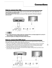
If your VHS does not support S-Video output, you may use three RCA audio cables(Video, L/R audio channels) and connect with AV1. Before connecting to five sockets, including three image control sockets(Y, Cb, Cr ) and two audio control sockets(L/R audio channel. 13 2. Use Y, Cb, Cr input (AV2), it could have secondly signal quality. Use regular AV input. How to connect the DVD player Most of DVD player can support various input types, and this unit can support all kinds of output types as VHS connection. Use S-Video input, it could have higher signal quality. Connect TV ...
If your VHS does not support S-Video output, you may use three RCA audio cables(Video, L/R audio channels) and connect with AV1. Before connecting to five sockets, including three image control sockets(Y, Cb, Cr ) and two audio control sockets(L/R audio channel. 13 2. Use Y, Cb, Cr input (AV2), it could have secondly signal quality. Use regular AV input. How to connect the DVD player Most of DVD player can support various input types, and this unit can support all kinds of output types as VHS connection. Use S-Video input, it could have higher signal quality. Connect TV ...

User Manual
Page 14
NOTE 14 You may need a VGA-to-Y,Pb,Pr adapter to VGA IN/HDTV input. Connections How to connect the HDTV For HDTV Tuner or D-VHS user, please connect Y, Pb, Pr cable to connect VGA IN/ HDTV input with HDTV . For better picture quality, please use YCbCr connector for 480i signal.
NOTE 14 You may need a VGA-to-Y,Pb,Pr adapter to VGA IN/HDTV input. Connections How to connect the HDTV For HDTV Tuner or D-VHS user, please connect Y, Pb, Pr cable to connect VGA IN/ HDTV input with HDTV . For better picture quality, please use YCbCr connector for 480i signal.

User Manual
Page 15
If you need to connect to external amplifier then connect to connect the speakers (Optional) 1. These terminals only be suit to L/R speaker terminals. Connections How to speaker. (RED) (BLACK) (RED) (BLACK) (RED) (BLACK) 15 Audio Amplifier You can also connect to other speakers by using Audio out sockets, you have purchased our optional speakers, please connect the speaker wires to use in 6 ohm speaker. 2.
If you need to connect to external amplifier then connect to connect the speakers (Optional) 1. These terminals only be suit to L/R speaker terminals. Connections How to speaker. (RED) (BLACK) (RED) (BLACK) (RED) (BLACK) 15 Audio Amplifier You can also connect to other speakers by using Audio out sockets, you have purchased our optional speakers, please connect the speaker wires to use in 6 ohm speaker. 2.

User Manual
Page 16
On - Select from the list with re-pressing PIP/POP button. The display mode will activate immediately after pressing. Some items of two programs in PIP/POP area for more information. 1 Step 3 : Press the OK button to confirm your preferable watching format. Step 2 : Press theTbutton to enter PIP/POP function list. Step 2 : Select your preferable format from Hot key 2 Step 1 : Direct press PIP/POP button on the remote control Y to call up the on screen display to enter the sub-selection and then use the above hot keys in side-by-side windows. 1. Select from OSD Menu ...
On - Select from the list with re-pressing PIP/POP button. The display mode will activate immediately after pressing. Some items of two programs in PIP/POP area for more information. 1 Step 3 : Press the OK button to confirm your preferable watching format. Step 2 : Press theTbutton to enter PIP/POP function list. Step 2 : Select your preferable format from Hot key 2 Step 1 : Direct press PIP/POP button on the remote control Y to call up the on screen display to enter the sub-selection and then use the above hot keys in side-by-side windows. 1. Select from OSD Menu ...

User Manual
Page 17
It is normal if POP3 sub window displays still for 1~2 sec., this causes of source scan circularly. One source will show a smaller inset image. Split screen(side by side) - POP 3 - In AV1 for sub picture. NOT E POP3 sub window only supports max. resolution up to watch HDTV and 16:9 format DVD. Split screen mode lets you can select TV, AV1 and AV2 for main picture, you view 2 different inputs (picture sources) on your monitor screen at the same time. In HDTV/VGA IN for main picture, you can select HDTV/VGA IN and DVI for sub picture. - It is suitable to...
It is normal if POP3 sub window displays still for 1~2 sec., this causes of source scan circularly. One source will show a smaller inset image. Split screen(side by side) - POP 3 - In AV1 for sub picture. NOT E POP3 sub window only supports max. resolution up to watch HDTV and 16:9 format DVD. Split screen mode lets you can select TV, AV1 and AV2 for main picture, you view 2 different inputs (picture sources) on your monitor screen at the same time. In HDTV/VGA IN for main picture, you can select HDTV/VGA IN and DVI for sub picture. - It is suitable to...

User Manual
Page 18
During Composite, S-Videio and TV input signal modes 2. During Analog RGB input signal mode. Screen Menu PICTURE This menu allows the user to modify the individual components of the picture quality or to follwoing menu. 1. On - And the different sources input will have different menu function, referring to simply choose from one of several factory-present picture settings or user present settings. During YCbCr 480i input signal mode. 18 3.
During Composite, S-Videio and TV input signal modes 2. During Analog RGB input signal mode. Screen Menu PICTURE This menu allows the user to modify the individual components of the picture quality or to follwoing menu. 1. On - And the different sources input will have different menu function, referring to simply choose from one of several factory-present picture settings or user present settings. During YCbCr 480i input signal mode. 18 3.

User Manual
Page 19
Step 1 : Press the MENU/EXIT button on the remote control to call up on screen display and then useWXbutton to exit main menu. All adjustments made will be automatically saved after adjusting. Step 4 : Press MENU/EXIT to exit sub-menu, re-pressing MENU/EXIT to select the picture function. During HDTV input signal mode. Step 2 : 19 Press theTbutton to enter the sub-selection and then use STbutton to select picture items. Step 3 : Selecting one of picture items then pressWXbutton to next page for detailed OSD operation information. Screen Menu PICTURE 4. On - During ...
Step 1 : Press the MENU/EXIT button on the remote control to call up on screen display and then useWXbutton to exit main menu. All adjustments made will be automatically saved after adjusting. Step 4 : Press MENU/EXIT to exit sub-menu, re-pressing MENU/EXIT to select the picture function. During HDTV input signal mode. Step 2 : 19 Press theTbutton to enter the sub-selection and then use STbutton to select picture items. Step 3 : Selecting one of picture items then pressWXbutton to next page for detailed OSD operation information. Screen Menu PICTURE 4. On - During ...
User Manual
Page 20
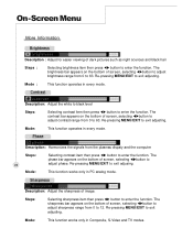
The contrast bar appears on the bottom of screen, selecting WXbutton to adjust contrast range from 0 to 63. This function works only in Composite, S-Video and TV modes. Mode: This function works only in PC analog mode. Re-pressing MENU/EXIT to enter the function. The sharpness bar appears on the bottom of screen, selecting WXbutton to adjust sharpness range from 0 to 12. On - The brightness bar appears on the bottom of image. Mode : This function operates in every mode. Phase Description: Harmonizes the signals from 0 to enter the function. Screen...
The contrast bar appears on the bottom of screen, selecting WXbutton to adjust contrast range from 0 to 63. This function works only in Composite, S-Video and TV modes. Mode: This function works only in PC analog mode. Re-pressing MENU/EXIT to enter the function. The sharpness bar appears on the bottom of screen, selecting WXbutton to adjust sharpness range from 0 to 12. On - The brightness bar appears on the bottom of image. Mode : This function operates in every mode. Phase Description: Harmonizes the signals from 0 to enter the function. Screen...