

Technical Reference
Page 3
.... • Keep the fluid out of reach of the power cord • Do not damage, break, or modify the power cord. What is specifically prohibited is dangerous for them from the outlet, and contact the dealer, or Support Center. Warning Always ground the connections • Always connect the printer's ground wire to conduct internal inspections, adjustments, and repairs. It is...
.... • Keep the fluid out of reach of the power cord • Do not damage, break, or modify the power cord. What is specifically prohibited is dangerous for them from the outlet, and contact the dealer, or Support Center. Warning Always ground the connections • Always connect the printer's ground wire to conduct internal inspections, adjustments, and repairs. It is...

Technical Reference
Page 6
...Font Download Mode 3-15 3.8 Default Setting Mode 3-16 3.9 HEX Dump Mode 3-17 3.10 Error Occurrence While Downloading 3-17 3.11 Printer Configurations Setting 3-18 Troubleshooting 4-1 4.1 Error signal troubleshooting 4-2 4.2 Troubleshooting table 4-4 4.3 Interface troubleshooting 4-6 4.4 Test print troubleshooting 4-7 Cleaning and Maintenance 5-1 5.1 Cleaning The Print Head, Platen and Rollers 5-2 5.2 How To Clean The Printer (Cleaning Kit 5-2 5.3 How To Clean The Printer (Cleaning Sheet 5-3 5.4 Easy Replacement of Parts 5-4 5.5 Adjusting Print Quality 5-7 General Specifications...
...Font Download Mode 3-15 3.8 Default Setting Mode 3-16 3.9 HEX Dump Mode 3-17 3.10 Error Occurrence While Downloading 3-17 3.11 Printer Configurations Setting 3-18 Troubleshooting 4-1 4.1 Error signal troubleshooting 4-2 4.2 Troubleshooting table 4-4 4.3 Interface troubleshooting 4-6 4.4 Test print troubleshooting 4-7 Cleaning and Maintenance 5-1 5.1 Cleaning The Print Head, Platen and Rollers 5-2 5.2 How To Clean The Printer (Cleaning Kit 5-2 5.3 How To Clean The Printer (Cleaning Sheet 5-3 5.4 Easy Replacement of Parts 5-4 5.5 Adjusting Print Quality 5-7 General Specifications...

Technical Reference
Page 9
... using Keypad • Tool-less changing of the printer. All page numbers in this OKI printer product. With a 32-bit RISC CPU, 4 ips print speed, and 4MB Flash Memory, the LD610 Series is 4 inch Compact Desktop printer (Thermal Transfer or Direct Thermal). The key features of the LD610 Series are organized as follows: Section 1: Introduction Section 2: Installation Section 3: Operation and Configuration Section 4: Troubleshooting Section 5: Cleaning and Maintenance Section 6: General Specifications Section 7: Interface Specifications...
... using Keypad • Tool-less changing of the printer. All page numbers in this OKI printer product. With a 32-bit RISC CPU, 4 ips print speed, and 4MB Flash Memory, the LD610 Series is 4 inch Compact Desktop printer (Thermal Transfer or Direct Thermal). The key features of the LD610 Series are organized as follows: Section 1: Introduction Section 2: Installation Section 3: Operation and Configuration Section 4: Troubleshooting Section 5: Cleaning and Maintenance Section 6: General Specifications Section 7: Interface Specifications...
Technical Reference
Page 11
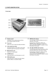
... Page 1-3 During printer configuration setting, the ERROR indicator responses in the printer. 1.3 PARTS IDENTIFICATION Front view 1 2 3 4 Section 1: Introduction 5 6 7 8 1 Operator panel It consists of two contact buttons and two LED indicators (green and red). 2 Top cover Open this cover to load the media and ribbon. 3 Cover open/close latch Pull these latches on both sides of the printer forward to open the Top cover of the printer. 4 Media ejection slot Opening for media output. 5 POWER button Press this button to turn...
... Page 1-3 During printer configuration setting, the ERROR indicator responses in the printer. 1.3 PARTS IDENTIFICATION Front view 1 2 3 4 Section 1: Introduction 5 6 7 8 1 Operator panel It consists of two contact buttons and two LED indicators (green and red). 2 Top cover Open this cover to load the media and ribbon. 3 Cover open/close latch Pull these latches on both sides of the printer forward to open the Top cover of the printer. 4 Media ejection slot Opening for media output. 5 POWER button Press this button to turn...

Technical Reference
Page 23
... the top cover. See Section 3.3 User Test Print Mode for instructions on the inner side of the print head with your fingers pinched while closing the top cover. 7. Caution • When replacing carbon ribbon, bear in mind that the media roll and ribbon have been loaded properly. Close the top cover until it up unit. Note: • Be careful not to check that the print head and its...
... the top cover. See Section 3.3 User Test Print Mode for instructions on the inner side of the print head with your fingers pinched while closing the top cover. 7. Caution • When replacing carbon ribbon, bear in mind that the media roll and ribbon have been loaded properly. Close the top cover until it up unit. Note: • Be careful not to check that the print head and its...

Technical Reference
Page 31
... FEED/LINE button until the desired mode While pressing lighting pattern is shown. Operation Setting mode: • Program download mode • Font download mode • Default setting mode • HEX Dump mode • USB interface • RS-232C/ LAN/ IEEE 1284 interface • Keypad selection • Scanner, Smart keyboard You can set the printer in any of the following flow chart provides a clear summary of each of the modes and its access method. User Test print mode...
... FEED/LINE button until the desired mode While pressing lighting pattern is shown. Operation Setting mode: • Program download mode • Font download mode • Default setting mode • HEX Dump mode • USB interface • RS-232C/ LAN/ IEEE 1284 interface • Keypad selection • Scanner, Smart keyboard You can set the printer in any of the following flow chart provides a clear summary of each of the modes and its access method. User Test print mode...

Technical Reference
Page 32
... will continuously print the user test labels until the FEED/LINE button is pressed. Green light Off Press FEED/LINE button to next mode as long as the FEED/LINE button is held down.) User Test Print mode. Preparation: Make sure the media or ribbon (if required) are properly loaded in step 2 above, just keep holding FEED/LINE button. Printer status Printer start-up ON LINE (POWER) indicator ERROR indicator Off Red light Buzzer 2 Release FEED/LINE button when ON LINE (POWER) indicator changes to green light and single...
... will continuously print the user test labels until the FEED/LINE button is pressed. Green light Off Press FEED/LINE button to next mode as long as the FEED/LINE button is held down.) User Test Print mode. Preparation: Make sure the media or ribbon (if required) are properly loaded in step 2 above, just keep holding FEED/LINE button. Printer status Printer start-up ON LINE (POWER) indicator ERROR indicator Off Red light Buzzer 2 Release FEED/LINE button when ON LINE (POWER) indicator changes to green light and single...

Technical Reference
Page 34
Section 3: Operation and Configuration 3.3 USER TEST PRINT MODE (cont'd) Second print-out (Protocol code setting values) No. 1 STX 2 ETX 3 ESC 4 ENQ 5 CAN 6 NULL 7 OFFLINE 8 AUTO ONLINE 9 ZERO SLASH 10 EURO Print Item Zero slash Euro code Third print-out (Interface) USB and RS-232C interface on board No. 1 Selected Interface Print Item In-use interface 2 Interface 1 3 Buffer Type 4 Protocol 5 Serial No. 6 Interface 2 Interface 1 Buffer type Protocol Serial No. Interface 2 Communication parameters 7 Buffer Type 8 Protocol...
Section 3: Operation and Configuration 3.3 USER TEST PRINT MODE (cont'd) Second print-out (Protocol code setting values) No. 1 STX 2 ETX 3 ESC 4 ENQ 5 CAN 6 NULL 7 OFFLINE 8 AUTO ONLINE 9 ZERO SLASH 10 EURO Print Item Zero slash Euro code Third print-out (Interface) USB and RS-232C interface on board No. 1 Selected Interface Print Item In-use interface 2 Interface 1 3 Buffer Type 4 Protocol 5 Serial No. 6 Interface 2 Interface 1 Buffer type Protocol Serial No. Interface 2 Communication parameters 7 Buffer Type 8 Protocol...

Technical Reference
Page 36
Printer status Printer start-up ON LINE (POWER) indicator ERROR indicator Off Red light Buzzer 2 Release FEED/LINE button when ERROR indicator changes to red light and two short beeps sound are properly loaded in step 2 above, just keep holding FEED/LINE button. FEED/LINE released Factory Test Print mode is held down.) User Test Print Mode. FactoryTest Print start test printing. Press again to pause the test printing. The printing is paused and will resume printing if the FEED/LINE button is pressed. Keep holding the FEED/ LINE button and wait for...
Printer status Printer start-up ON LINE (POWER) indicator ERROR indicator Off Red light Buzzer 2 Release FEED/LINE button when ERROR indicator changes to red light and two short beeps sound are properly loaded in step 2 above, just keep holding FEED/LINE button. FEED/LINE released Factory Test Print mode is held down.) User Test Print Mode. FactoryTest Print start test printing. Press again to pause the test printing. The printing is paused and will resume printing if the FEED/LINE button is pressed. Keep holding the FEED/ LINE button and wait for...

Technical Reference
Page 39
... Keep holding FEED/LINE button. Factory Test Print Mode Green light Off Off Red light Operation Setting Mode Blinking green light Off One short beep Two short beeps Three short beeps To be continued on the next page. Section 3: Operation and Configuration 3.5 OPERATION SETTING MODE The operation setting mode enables further selection of the functions of the above operation setting modes are as the FEED/LINE button is held down.) User Test Print Mode. These are: • Program download mode • Font download mode • Default setting mode • HEX dump mode • USB...
... Keep holding FEED/LINE button. Factory Test Print Mode Green light Off Off Red light Operation Setting Mode Blinking green light Off One short beep Two short beeps Three short beeps To be continued on the next page. Section 3: Operation and Configuration 3.5 OPERATION SETTING MODE The operation setting mode enables further selection of the functions of the above operation setting modes are as the FEED/LINE button is held down.) User Test Print Mode. These are: • Program download mode • Font download mode • Default setting mode • HEX dump mode • USB...
Technical Reference
Page 42
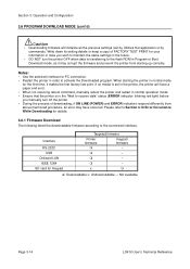
... the printer from starting the printer in the future. • DO NOT turn the printer OFF when data is in order to receive data" status (ERROR indicator: blinking red light) before you wish to maintain the same settings in normal mode for details. 3.6.1 Firmware Download The following listed the downloadable firmware according to the flash ROM in Program or Boot Download mode, as it makes the first factory test print. If no media is set by...
... the printer from starting the printer in the future. • DO NOT turn the printer OFF when data is in order to receive data" status (ERROR indicator: blinking red light) before you wish to maintain the same settings in normal mode for details. 3.6.1 Firmware Download The following listed the downloadable firmware according to the flash ROM in Program or Boot Download mode, as it makes the first factory test print. If no media is set by...
Technical Reference
Page 43
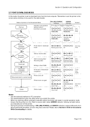
... normal mode At the start of download mode Wait to receive data Start receiving data/ Receiving data Writing to flash ROM At the time of download completion Printer turns off the printer. • During the process of Operation Setting Mode. ) Buzzer Off (while pressing FEED/LINE) Off (while pressing FEED/LINE) One short beep No Reception from the host computer. Section 3: Operation and Configuration 3.7 FONT DOWNLOAD MODE In this mode, the printer is set the printer to...
... normal mode At the start of download mode Wait to receive data Start receiving data/ Receiving data Writing to flash ROM At the time of download completion Printer turns off the printer. • During the process of Operation Setting Mode. ) Buzzer Off (while pressing FEED/LINE) Off (while pressing FEED/LINE) One short beep No Reception from the host computer. Section 3: Operation and Configuration 3.7 FONT DOWNLOAD MODE In this mode, the printer is set the printer to...

Technical Reference
Page 44
Items to the default setting (factory preset) as listed below. To be reset Default value 1 Offset (V, H) 2 Pitch Offset 3 Cut Offset 4 Dispensing Offset 5 Tear-Off Offset 6 Label Size 7 Print Speed 8 Print Darkness 9 Sensor Type 10 Paper End Search 11 Zero Slash 12 Proportional Pitch 13 Initial Feed 14 Auto Feed 15 Operation mode Continuous Tear Off Cutter Dispenser 16 Interface RS-232C LAN IEEE 1284 USB Vertical = 0 dot, Horizontal...
Items to the default setting (factory preset) as listed below. To be reset Default value 1 Offset (V, H) 2 Pitch Offset 3 Cut Offset 4 Dispensing Offset 5 Tear-Off Offset 6 Label Size 7 Print Speed 8 Print Darkness 9 Sensor Type 10 Paper End Search 11 Zero Slash 12 Proportional Pitch 13 Initial Feed 14 Auto Feed 15 Operation mode Continuous Tear Off Cutter Dispenser 16 Interface RS-232C LAN IEEE 1284 USB Vertical = 0 dot, Horizontal...
Technical Reference
Page 54
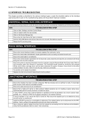
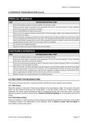
... able, configure the appropriate protocols and retest connectivity. Use a crossover cable to isolate the problem. Click on Start, Settings, and then Control Panel. Ensure the serial cable is correctly installed. Ensure that all parameters are not creating a queue setup issue. If using the Receive Buffer Hex Dump mode. Click on another port to isolate the printer from the network by trying the print server on System within this manual for instructions. Scroll...
... able, configure the appropriate protocols and retest connectivity. Use a crossover cable to isolate the problem. Click on Start, Settings, and then Control Panel. Ensure the serial cable is correctly installed. Ensure that all parameters are not creating a queue setup issue. If using the Receive Buffer Hex Dump mode. Click on another port to isolate the printer from the network by trying the print server on System within this manual for instructions. Scroll...
Technical Reference
Page 55
... the printer cable is connected to the appropriate LPT port on special printing to identify and resolve specific print problems. 4.4.1 Hex Dump Allows the operator to Section 3.9 HEX Dump Mode for instructions. Refer to determine if there were problems in the identification of data received is correctly installed. CENTRONICS INTERFACE CHK TROUBLESHOOTING STEP Ensure the interface module is numbered. Ensure the host's peripheral settings are set for Centronics output...
... the printer cable is connected to the appropriate LPT port on special printing to identify and resolve specific print problems. 4.4.1 Hex Dump Allows the operator to Section 3.9 HEX Dump Mode for instructions. Refer to determine if there were problems in the identification of data received is correctly installed. CENTRONICS INTERFACE CHK TROUBLESHOOTING STEP Ensure the interface module is numbered. Ensure the host's peripheral settings are set for Centronics output...
Technical Reference
Page 58
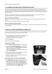
... clean with a cleaning kit ♦ For the print head, platen roller, paper sensor, and label guide: clean after it before cleaning. Make sure the printer is the black rubber roller near the front panel. Apply Thermal Print Head Cleaner to remove it is mounted under the Top cover. Press the end of the dampened swab along the front edge of media. Cleaning the platen roller, sensor and label guide 8. The platen roller is powered...
... clean with a cleaning kit ♦ For the print head, platen roller, paper sensor, and label guide: clean after it before cleaning. Make sure the printer is the black rubber roller near the front panel. Apply Thermal Print Head Cleaner to remove it is mounted under the Top cover. Press the end of the dampened swab along the front edge of media. Cleaning the platen roller, sensor and label guide 8. The platen roller is powered...

Technical Reference
Page 63
... adjustment allows the user to control (within a specified range) the amount of power that is highly recommended for good barcode quality. Instead, the edges of each image should the edges of controlling print quality is important to allow the head to cool sufficiently before stepping to find a proper print darkness level based on the trailing edge. LD610 User's Technical Reference Page 5-7 The adjustment...
... adjustment allows the user to control (within a specified range) the amount of power that is highly recommended for good barcode quality. Instead, the edges of each image should the edges of controlling print quality is important to allow the head to cool sufficiently before stepping to find a proper print darkness level based on the trailing edge. LD610 User's Technical Reference Page 5-7 The adjustment...
Technical Reference
Page 76
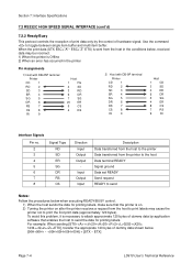
...). Section 7: Interface Specifications 7.2 RS232C HIGH SPEED SERIAL INTERFACE (cont'd) 7.2.2 Ready/Busy This protocol controls the reception of print data only by the control of dummy data by application software that the printer is necessary to attach approximate 120 bytes of hardware signal. Use the command to send the data for printing labels. For example: When sending [STX++20+20+2+0202+, 1234+2++ETX], transfer the appropriate...
...). Section 7: Interface Specifications 7.2 RS232C HIGH SPEED SERIAL INTERFACE (cont'd) 7.2.2 Ready/Busy This protocol controls the reception of print data only by the control of dummy data by application software that the printer is necessary to attach approximate 120 bytes of hardware signal. Use the command to send the data for printing labels. For example: When sending [STX++20+20+2+0202+, 1234+2++ETX], transfer the appropriate...

Technical Reference
Page 82
... Print Support] in addition to the printer driver to the USB interface is [Windows2000/XP/Server2003/Vista], however, the connection may not be "Serial number". For example: CRGY0032 Page 7-10 LD610 User's Technical Reference Notes • OS environment corresponding to perform print operation via the USB port. Section 7: Interface Specifications 7.4 UNIVERSAL SERIAL BUS (USB) INTERFACE (cont'd) 7.4.3 Host Computer Settings Installation of USB port should be established depending on the manufacturers or models...
... Print Support] in addition to the printer driver to the USB interface is [Windows2000/XP/Server2003/Vista], however, the connection may not be "Serial number". For example: CRGY0032 Page 7-10 LD610 User's Technical Reference Notes • OS environment corresponding to perform print operation via the USB port. Section 7: Interface Specifications 7.4 UNIVERSAL SERIAL BUS (USB) INTERFACE (cont'd) 7.4.3 Host Computer Settings Installation of USB port should be established depending on the manufacturers or models...

Technical Reference
Page 83
... supported network protocols using a 10/100BaseT LAN connection. Interface connector Link/Status LED Cable type: For 10BASE-T and 100BASE-TX Cable length: 100m or less Status LED lights up when collision occurs Maintenance function Interface type [Printing LAN configuration information] LAN configuration information will be printed on the third sheet of user test print and factory test print. [Initializing LAN configuration information] LAN configuration information will be loaded on the host computer and configured to the authorized OKI servicing...
... supported network protocols using a 10/100BaseT LAN connection. Interface connector Link/Status LED Cable type: For 10BASE-T and 100BASE-TX Cable length: 100m or less Status LED lights up when collision occurs Maintenance function Interface type [Printing LAN configuration information] LAN configuration information will be printed on the third sheet of user test print and factory test print. [Initializing LAN configuration information] LAN configuration information will be loaded on the host computer and configured to the authorized OKI servicing...


