GS7xxTS-TPS Hardware Installation Guide
Page 3
... Package Contents 10 Chapter 2 Physical Description GS728TS Front-Panel and Back-Panel Configuration 12 GS728TPS Front-Panel and Back-Panel Configuration 13 GS752TS Front-Panel and Back-Panel Configuration 15 GS752TPS Front-Panel and Back-Panel Configuration 16 LED Designations 17 RJ-45 Port LEDs 17 ...SFP Port LEDs 18 System LEDs 18 Device Hardware Interfaces 19 RJ-45 Ports 19 SFP Ports 19 Reset Button 20 Factory Defaults Button 20 Select Button 20 Chapter 3 Applications Desktop Switching 22 Backbone Switching 23 Chapter 4 Installation Step 1: Preparing the ...
... Package Contents 10 Chapter 2 Physical Description GS728TS Front-Panel and Back-Panel Configuration 12 GS728TPS Front-Panel and Back-Panel Configuration 13 GS752TS Front-Panel and Back-Panel Configuration 15 GS752TPS Front-Panel and Back-Panel Configuration 16 LED Designations 17 RJ-45 Port LEDs 17 ...SFP Port LEDs 18 System LEDs 18 Device Hardware Interfaces 19 RJ-45 Ports 19 SFP Ports 19 Reset Button 20 Factory Defaults Button 20 Select Button 20 Chapter 3 Applications Desktop Switching 22 Backbone Switching 23 Chapter 4 Installation Step 1: Preparing the ...
GS7xxTS-TPS Hardware Installation Guide
Page 12
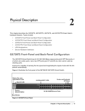
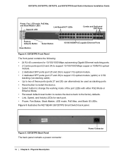
...Stack ID LED Link/Speed/ACT LEDs Combo and Dedicated SFP Ports Factory Defaults Button Reset Button Figure 2. Topics include: • GS728TS Front-Panel and Back-Panel Configuration • GS728TPS Front-Panel and Back-Panel Configuration • GS752TS Front-Panel and Back-Panel Configuration • GS752TPS Front-Panel ...sensing the line speed and negotiating the duplex mode with the link partner automatically. Physical Description 2 This chapter describes the GS728TS, GS728TPS, GS752TS, and GS752TPS Smart Switch hardware features. Figure 2 illustrates the front panel of the...
...Stack ID LED Link/Speed/ACT LEDs Combo and Dedicated SFP Ports Factory Defaults Button Reset Button Figure 2. Topics include: • GS728TS Front-Panel and Back-Panel Configuration • GS728TPS Front-Panel and Back-Panel Configuration • GS752TS Front-Panel and Back-Panel Configuration • GS752TPS Front-Panel ...sensing the line speed and negotiating the duplex mode with the link partner automatically. Physical Description 2 This chapter describes the GS728TS, GS728TPS, GS752TS, and GS752TPS Smart Switch hardware features. Figure 2 illustrates the front panel of the...
GS7xxTS-TPS Hardware Installation Guide
Page 13
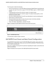
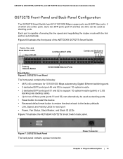
Up to the factory defaults. • Link, Speed, and Activity LEDs for 10/100/1000 Mbps ... the device. • Recessed default reset button to restore the device back to two SFP ports (port 27 and 28) at a time can be used as stacking ports. GS728TS, GS728TPS, GS752TS, and GS752TPS Smart Switch Hardware Installation ... duplex mode with the link partner automatically. Each port is capable of the NETGEAR GS728TPS Smart Switch. Physical Description | 13 Figure 3 illustrates the NETGEAR GS728TS Smart Switch back panel. Chapter 2. Power Connector GS728TPS Front-Panel and...
Up to the factory defaults. • Link, Speed, and Activity LEDs for 10/100/1000 Mbps ... the device. • Recessed default reset button to restore the device back to two SFP ports (port 27 and 28) at a time can be used as stacking ports. GS728TS, GS728TPS, GS752TS, and GS752TPS Smart Switch Hardware Installation ... duplex mode with the link partner automatically. Each port is capable of the NETGEAR GS728TPS Smart Switch. Physical Description | 13 Figure 3 illustrates the NETGEAR GS728TS Smart Switch back panel. Chapter 2. Power Connector GS728TPS Front-Panel and...
GS7xxTS-TPS Hardware Installation Guide
Page 14
GS728TS, GS728TPS, GS752TS, and GS752TPS Smart Switch Hardware Installation Guide Power, Fan, LED mode, PoE Max, and Stack Master LEDs Stack ID LED Link/Speed/ACT LEDs Combo and Dedicated SFP Ports Factory Defaults Button Reset Button Select Button 10/100/1000M PoE capable ...Ethernet Ports Figure 4. GS728TPS Back Panel The back panel contains a power connector. 14 | Chapter 2. Physical Description Power Connector Figure 5 illustrates the NETGEAR GS728TPS Smart Switch back panel...
GS728TS, GS728TPS, GS752TS, and GS752TPS Smart Switch Hardware Installation Guide Power, Fan, LED mode, PoE Max, and Stack Master LEDs Stack ID LED Link/Speed/ACT LEDs Combo and Dedicated SFP Ports Factory Defaults Button Reset Button Select Button 10/100/1000M PoE capable ...Ethernet Ports Figure 4. GS728TPS Back Panel The back panel contains a power connector. 14 | Chapter 2. Physical Description Power Connector Figure 5 illustrates the NETGEAR GS728TPS Smart Switch back panel...
GS7xxTS-TPS Hardware Installation Guide
Page 15
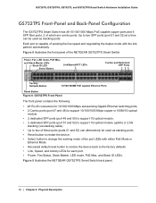
...ID LEDs Figure 7 illustrates the NETGEAR GS752TS Smart Switch back panel. Physical Description | 15 Power, Fan, and Stack Master LEDs Stack ID LED Link/Speed/ACT LEDs Combo and Dedicated SFP Ports Factory Defaults Button 10/100/1000M Ethernet Ports Reset Button Figure 6. Power Connector ...Chapter 2. Figure 7. Each port is capable of the NETGEAR GS752TS Smart Switch. Figure 6 illustrates the front panel of sensing ...
...ID LEDs Figure 7 illustrates the NETGEAR GS752TS Smart Switch back panel. Physical Description | 15 Power, Fan, and Stack Master LEDs Stack ID LED Link/Speed/ACT LEDs Combo and Dedicated SFP Ports Factory Defaults Button 10/100/1000M Ethernet Ports Reset Button Figure 6. Power Connector ...Chapter 2. Figure 7. Each port is capable of the NETGEAR GS752TS Smart Switch. Figure 6 illustrates the front panel of sensing ...
GS7xxTS-TPS Hardware Installation Guide
Page 16
GS728TS, GS728TPS, GS752TS, and GS752TPS Smart Switch Hardware Installation Guide GS752TPS Front-Panel and Back-Panel Configuration The GS752TPS Smart Switch has 48 10/100/1000 Mbps PoE capable copper ports and 6 SFP fiber ports, 2 of the NETGEAR GS752TPS Smart Switch. Figure 8 illustrates the front panel of..., PoE Max, and Stack Master LEDs Stack ID LED Select Button Link/Speed/ACT LEDs Combo and Dedicated SFP Ports Factory Defaults Button 10/100/1000M PoE capable Ethernet Ports Reset Button Figure 8. Each port is capable of the port LEDs with the link partner automatically.
GS728TS, GS728TPS, GS752TS, and GS752TPS Smart Switch Hardware Installation Guide GS752TPS Front-Panel and Back-Panel Configuration The GS752TPS Smart Switch has 48 10/100/1000 Mbps PoE capable copper ports and 6 SFP fiber ports, 2 of the NETGEAR GS752TPS Smart Switch. Figure 8 illustrates the front panel of..., PoE Max, and Stack Master LEDs Stack ID LED Select Button Link/Speed/ACT LEDs Combo and Dedicated SFP Ports Factory Defaults Button 10/100/1000M PoE capable Ethernet Ports Reset Button Figure 8. Each port is capable of the port LEDs with the link partner automatically.

GS7xxTS-TPS Hardware Installation Guide
Page 20
..., insert a device such as a paper clip into the switch as a stacking cable. Factory Defaults Button The Smart Switch has a Factory Defaults button on the front panel to allow you enable the Factory Defaults button, all settings including the password, VLAN settings, and port configurations are removed.... LED mode of the ports between Ethernet and PoE status. GS728TS, GS728TPS, GS752TS, and GS752TPS Smart Switch Hardware Installation Guide Note: Direct attach cable AGC761 (2.5G) is recommended to be used as it resets. Select Button The Smart Switch GS728TP and GS752TP have a LED Mode Select...
..., insert a device such as a paper clip into the switch as a stacking cable. Factory Defaults Button The Smart Switch has a Factory Defaults button on the front panel to allow you enable the Factory Defaults button, all settings including the password, VLAN settings, and port configurations are removed.... LED mode of the ports between Ethernet and PoE status. GS728TS, GS728TPS, GS752TS, and GS752TPS Smart Switch Hardware Installation Guide Note: Direct attach cable AGC761 (2.5G) is recommended to be used as it resets. Select Button The Smart Switch GS728TP and GS752TP have a LED Mode Select...
GS7xxTS-TPS Hardware Installation Guide
Page 22
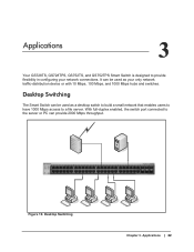
... 30 31 32 33 34 35 36 37 38 39 40 41 42 43 44 45 46 47 48 49F 50F GS752TXS 51F 52F SFP + Reset Factory Defaults Green=10G Link Yellow=1G Blink=ACT ` ` ` ` Figure 10. It can be used as a desktop switch to build a small network that enables ...only network traffic-distribution device or with 10 Mbps, 100 Mbps, and 1000 Mbps hubs and switches. Desktop Switching Chapter 3. Applications 3 Your GS728TS, GS728TPS, GS752TS, and GS752TPS Smart Switch is designed to a file server. Desktop Switching The Smart Switch can provide 2000 Mbps throughput. Applications | 22 3.
... 30 31 32 33 34 35 36 37 38 39 40 41 42 43 44 45 46 47 48 49F 50F GS752TXS 51F 52F SFP + Reset Factory Defaults Green=10G Link Yellow=1G Blink=ACT ` ` ` ` Figure 10. It can be used as a desktop switch to build a small network that enables ...only network traffic-distribution device or with 10 Mbps, 100 Mbps, and 1000 Mbps hubs and switches. Desktop Switching Chapter 3. Applications 3 Your GS728TS, GS728TPS, GS752TS, and GS752TPS Smart Switch is designed to a file server. Desktop Switching The Smart Switch can provide 2000 Mbps throughput. Applications | 22 3.

GS7xxTS-TPS Hardware Installation Guide
Page 23
... GS752TPS Smart Switch as a backbone switch in a small network that gives users high-speed access to servers and other network devices. GS752TS Power Fan Stack Master ID Link/Act Mode - 1 2 3 4 5 6 7 8 9 10 11 12 Green=Link at 1G Yellow=Link at 10/ 100M 13 14 15 16 17 ... 30 31 32 33 34 35 36 37 38 39 40 41 42 43 44 45 46 47 48 49F 50F GS752TXS 51F 52F SFP + Reset Factory Defaults Green=10G Link Yellow=1G Blink=ACT Model GS108T Model FS728TP ` ` Figure 11. Applications | 23 Backbone Switching ` ` ` Chapter...
... GS752TPS Smart Switch as a backbone switch in a small network that gives users high-speed access to servers and other network devices. GS752TS Power Fan Stack Master ID Link/Act Mode - 1 2 3 4 5 6 7 8 9 10 11 12 Green=Link at 1G Yellow=Link at 10/ 100M 13 14 15 16 17 ... 30 31 32 33 34 35 36 37 38 39 40 41 42 43 44 45 46 47 48 49F 50F GS752TXS 51F 52F SFP + Reset Factory Defaults Green=10G Link Yellow=1G Blink=ACT Model GS108T Model FS728TP ` ` Figure 11. Applications | 23 Backbone Switching ` ` ` Chapter...
GS7xxTS-TPS Hardware Installation Guide
Page 27
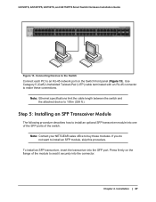
... (Cat5) Unshielded Twisted-Pair (UTP) cable terminated with an RJ-45 connector to make these modules. GS728TS, GS728TPS, GS752TS, and GS752TPS Smart Switch Hardware Installation Guide Power Fan Stack Master ID Link/Act Mode - 1 2 3 4 5 6...40 41 42 43 44 45 46 47 48 49F 50F GS752TXS 51F 52F SFP + Reset Factory Defaults Green=10G Link Yellow=1G Blink=ACT ` ` Figure 13. Connecting Devices to the...If you do not want to seat it securely into the SFP port. Note: Contact your NETGEAR sales office to 100m (328 ft.). Installation | 27 Press firmly on the Switch front panel...
... (Cat5) Unshielded Twisted-Pair (UTP) cable terminated with an RJ-45 connector to make these modules. GS728TS, GS728TPS, GS752TS, and GS752TPS Smart Switch Hardware Installation Guide Power Fan Stack Master ID Link/Act Mode - 1 2 3 4 5 6...40 41 42 43 44 45 46 47 48 49F 50F GS752TXS 51F 52F SFP + Reset Factory Defaults Green=10G Link Yellow=1G Blink=ACT ` ` Figure 13. Connecting Devices to the...If you do not want to seat it securely into the SFP port. Note: Contact your NETGEAR sales office to 100m (328 ft.). Installation | 27 Press firmly on the Switch front panel...
GS7xxTS-TPS Hardware Installation Guide
Page 41
...the Installation 26 Class of Service 7 compliance 39 Connecting Devices to the Switch 26, 27 Crossover 19 D Default Reset Button 13, 14, 15, 16 Device Hardware Interfaces 19 Duplex Mode 19 F Factory Default Button 20 Factory Defaults 13, 14, 15, 16 Flat Surface 25 Full-duplex 7 G Gigabit Ports 7 I IEEE 802.... Operating Conditions 25 Operating Environment 25 Operating humidity 25 Overview 7 P Package Contents 10 Pause Frame Flow Control 9 Preparing the Site 25 R Rackmount kit 10 Reset Button 13, 14, 15, 16 RJ-45 ports 7, 19 LEDs 17 Rubber footpads 10, 25 S Select Button 14, 16, 20 SFP ports 19 ...
...the Installation 26 Class of Service 7 compliance 39 Connecting Devices to the Switch 26, 27 Crossover 19 D Default Reset Button 13, 14, 15, 16 Device Hardware Interfaces 19 Duplex Mode 19 F Factory Default Button 20 Factory Defaults 13, 14, 15, 16 Flat Surface 25 Full-duplex 7 G Gigabit Ports 7 I IEEE 802.... Operating Conditions 25 Operating Environment 25 Operating humidity 25 Overview 7 P Package Contents 10 Pause Frame Flow Control 9 Preparing the Site 25 R Rackmount kit 10 Reset Button 13, 14, 15, 16 RJ-45 ports 7, 19 LEDs 17 Rubber footpads 10, 25 S Select Button 14, 16, 20 SFP ports 19 ...
GS7xxTS-TPS Software Admin Manual
Page 3
... of Service 45 DNS 49 Green Ethernet 51 Stacking 61 Stack Features 61 Firmware Synchronization and Upgrade 62 Configuration Maintenance 62 Stack Master Election 62 Factory Defaults Reset Behavior 63 Stack Configuration 63 Stack Port Configuration 66 Stack Port Diagnostics 68 Stack Firmware Synchronization 69 3
... of Service 45 DNS 49 Green Ethernet 51 Stacking 61 Stack Features 61 Firmware Synchronization and Upgrade 62 Configuration Maintenance 62 Stack Master Election 62 Factory Defaults Reset Behavior 63 Stack Configuration 63 Stack Port Configuration 66 Stack Port Diagnostics 68 Stack Firmware Synchronization 69 3

GS7xxTS-TPS Software Admin Manual
Page 7
... 272 Server Log Configuration 274 Trap Logs 276 Event Logs 277 Port Mirroring 278 Multiple Port Mirroring 278 Chapter 8 Maintaining the System Reset 280 Device Reboot 280 Factory Default 281 Upload File From Switch 282 TFTP File Upload 282 HTTP File Upload 283 Download File To Switch 284 TFTP File Download... Help 296 Support 296 User Guide 297 Registration 298 Appendix A Hardware Specifications and Default Values Switch Specifications 300 GS728TS Specifications 300 GS728TPS Specifications 300 GS752TS Specifications 301 GS752TPS Specifications 301 Switch Performance 301 7
... 272 Server Log Configuration 274 Trap Logs 276 Event Logs 277 Port Mirroring 278 Multiple Port Mirroring 278 Chapter 8 Maintaining the System Reset 280 Device Reboot 280 Factory Default 281 Upload File From Switch 282 TFTP File Upload 282 HTTP File Upload 283 Download File To Switch 284 TFTP File Download... Help 296 Support 296 User Guide 297 Registration 298 Appendix A Hardware Specifications and Default Values Switch Specifications 300 GS728TS Specifications 300 GS728TPS Specifications 300 GS752TS Specifications 301 GS752TPS Specifications 301 Switch Performance 301 7
GS7xxTS-TPS Software Admin Manual
Page 49
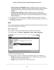
.... 2. Enable or disable this page to the latest value of the DNS Client. • Enable. The factory default is enabled by selecting the appropriate radio button. The factory default is disabled. • Denial of Service TCP SYN&FIN. If you change any of the DoS settings... Click Cancel to cancel the configuration on the screen and reset the data on the screen to configure global DNS settings and DNS server information. DNS Configuration Use this option by default. • Disable. GS728TS, GS728TPS, GS752TS, and GS752TPS Gigabit Smart Switches • Denial of Service ...
.... 2. Enable or disable this page to the latest value of the DNS Client. • Enable. The factory default is enabled by selecting the appropriate radio button. The factory default is disabled. • Denial of Service TCP SYN&FIN. If you change any of the DoS settings... Click Cancel to cancel the configuration on the screen and reset the data on the screen to configure global DNS settings and DNS server information. DNS Configuration Use this option by default. • Disable. GS728TS, GS728TPS, GS752TS, and GS752TPS Gigabit Smart Switches • Denial of Service ...
GS7xxTS-TPS Software Admin Manual
Page 63
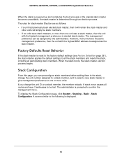
... before adding them to the stack, change the unit ID on page 281), the stack master applies the default settings to be lost. Factory Defaults Reset Behavior If the stack master is displayed. 63 A stack move . If you can be stack members. • If no units were... for stack master Election are as the stack master. A screen similar to the following is reset to the factory default settings (see Factory Default on a stack member, the member reloads. GS728TS, GS728TPS, GS752TS, and GS752TPS Gigabit Smart Switches When the stack is powered up and completes the boot process ...
... before adding them to the stack, change the unit ID on page 281), the stack master applies the default settings to be lost. Factory Defaults Reset Behavior If the stack master is displayed. 63 A stack move . If you can be stack members. • If no units were... for stack master Election are as the stack master. A screen similar to the following is reset to the factory default settings (see Factory Default on a stack member, the member reloads. GS728TS, GS728TPS, GS752TS, and GS752TPS Gigabit Smart Switches When the stack is powered up and completes the boot process ...
GS7xxTS-TPS Software Admin Manual
Page 78
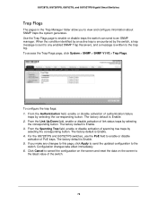
... by an active trap is written to the latest value of PoE traps. The factory default is Enable. 4. The factory default is Enable. 2. Click Cancel to cancel the configuration on the screen and reset the data on the screen to the trap log. To access the Trap Flags page..., click System > SNMP > SNMP V1/V2 > Trap Flags. If you to an SNMP manager. To configure the trap flags: 1. GS728TS, GS728TPS, GS752TS...
... by an active trap is written to the latest value of PoE traps. The factory default is Enable. 4. The factory default is Enable. 2. Click Cancel to cancel the configuration on the screen and reset the data on the screen to the trap log. To access the Trap Flags page..., click System > SNMP > SNMP V1/V2 > Trap Flags. If you to an SNMP manager. To configure the trap flags: 1. GS728TS, GS728TPS, GS752TS...
GS7xxTS-TPS Software Admin Manual
Page 104
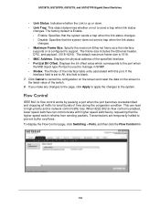
...does not send a trap when the link status changes. • Maximum Frame Size. GS728TS, GS728TPS, GS752TS, and GS752TPS Gigabit Smart Switches • Link Status. This object determines whether or not to the latest... value of the switch. 8. Click Cancel to cancel the configuration on the screen and reset the data on the screen to send a trap when link status changes. To display the Flow ... changes to the page, click Apply to apply the changes to All, this port. The factory default is set to the system. Specify the maximum Ethernet frame size the interface supports or...
...does not send a trap when the link status changes. • Maximum Frame Size. GS728TS, GS728TPS, GS752TS, and GS752TPS Gigabit Smart Switches • Link Status. This object determines whether or not to the latest... value of the switch. 8. Click Cancel to cancel the configuration on the screen and reset the data on the screen to send a trap when link status changes. To display the Flow ... changes to the page, click Apply to apply the changes to All, this port. The factory default is set to the system. Specify the maximum Ethernet frame size the interface supports or...
GS7xxTS-TPS Software Admin Manual
Page 105
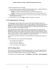
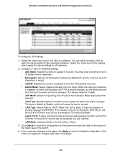
...LAG Configuration page, click Switching> LAG > Basic > LAG Configuration. 105 GS728TS, GS728TPS, GS752TS, and GS752TPS Gigabit Smart Switches To configure global flow control settings: 1. Network devices treat the ...if it were a single link. From the LAGs link, you to aggregate its member ports. The factory default is also known as a static member, it were a single link, which is Disable. &#...become full. • Disable. Click Cancel to cancel the configuration on the screen and reset the data on the system. If you create a LAG. Dynamic LAGs use Link Aggregation...
...LAG Configuration page, click Switching> LAG > Basic > LAG Configuration. 105 GS728TS, GS728TPS, GS752TS, and GS752TPS Gigabit Smart Switches To configure global flow control settings: 1. Network devices treat the ...if it were a single link. From the LAGs link, you to aggregate its member ports. The factory default is also known as a static member, it were a single link, which is Disable. &#...become full. • Disable. Click Cancel to cancel the configuration on the screen and reset the data on the system. If you create a LAG. Dynamic LAGs use Link Aggregation...
GS7xxTS-TPS Software Admin Manual
Page 106
...dropped. The default is Enable. • STP Mode. Click Cancel to cancel the configuration on the screen and reset the data on the screen to the latest value of up to 15 alphanumeric characters. • Description. Configuration ...You can be up to 64 characters in the heading row to apply the same settings to configure. The factory default is Static. • Active Ports. Select the check box next to the LAG to all the LACP... a LAG. Specify the name to assign to the LAG. GS728TS, GS728TPS, GS752TS, and GS752TPS Gigabit Smart Switches To configure LAG settings: 1.
...dropped. The default is Enable. • STP Mode. Click Cancel to cancel the configuration on the screen and reset the data on the screen to the latest value of up to 15 alphanumeric characters. • Description. Configuration ...You can be up to 64 characters in the heading row to apply the same settings to configure. The factory default is Static. • Active Ports. Select the check box next to the LAG to all the LACP... a LAG. Specify the name to assign to the LAG. GS728TS, GS728TPS, GS752TS, and GS752TPS Gigabit Smart Switches To configure LAG settings: 1.
GS7xxTS-TPS Software Admin Manual
Page 304
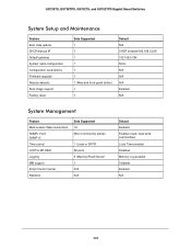
GS728TS, GS728TPS, GS752TS, and GS752TPS Gigabit Smart Switches System Setup and Maintenance Feature Boot code update DHCP/manual IP Default gateway System name configuration Configuration save/restore Firmware upgrade Restore defaults Dual image support Factory reset Sets Supported 1 1 1 1 1 1 1 (Web and front-panel button) 1 1 Default N/A DHCP enabled/192.168.0.239 192.168.0.254 NULL N/A N/A N/A Enabled...
GS728TS, GS728TPS, GS752TS, and GS752TPS Gigabit Smart Switches System Setup and Maintenance Feature Boot code update DHCP/manual IP Default gateway System name configuration Configuration save/restore Firmware upgrade Restore defaults Dual image support Factory reset Sets Supported 1 1 1 1 1 1 1 (Web and front-panel button) 1 1 Default N/A DHCP enabled/192.168.0.239 192.168.0.254 NULL N/A N/A N/A Enabled...

