
GS7xxTS-TPS Hardware Installation Guide
Page 7
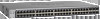
...Graphical User Interface (GUI), the switch's many capabilities can be viewed and used for high-speed networking. The NETGEAR GS728TS, GS728TPS, GS752TS, or GS752TPS Smart Switch can be free standing, stacked with a complete package of features for environments that have a mix of Ethernet, Fast Ethernet, or Gigabit Ethernet devices. Introduction | 7 Features The following list identifies the key features of Service (CoS) for traffic prioritization. The switch's management features include configuration for port and switch information, VLAN for traffic control, port trunking for...
...Graphical User Interface (GUI), the switch's many capabilities can be viewed and used for high-speed networking. The NETGEAR GS728TS, GS728TPS, GS752TS, or GS752TPS Smart Switch can be free standing, stacked with a complete package of features for environments that have a mix of Ethernet, Fast Ethernet, or Gigabit Ethernet devices. Introduction | 7 Features The following list identifies the key features of Service (CoS) for traffic prioritization. The switch's management features include configuration for port and switch information, VLAN for traffic control, port trunking for...

GS7xxTS-TPS Hardware Installation Guide
Page 9
... Smart Switch Hardware Installation Guide • GS7xxTPS model LEDs: Power and Status LED, FAN status LED, Master LED, LED mode LED and Max PoE LED. • Stack ID LED to display stack member ID (1-6). • Store-and-Forward transmission to remove bad packets from the network. • Full-duplex IEEE 802.3x pause frame flow control. • Active flow control to minimize packet loss and frame drops. • Half-duplex backpressure control. • Per port LEDs and power LED. • Internal open frame power supply. • Standard NETGEAR 7xx series chassis. • NETGEAR Green...
... Smart Switch Hardware Installation Guide • GS7xxTPS model LEDs: Power and Status LED, FAN status LED, Master LED, LED mode LED and Max PoE LED. • Stack ID LED to display stack member ID (1-6). • Store-and-Forward transmission to remove bad packets from the network. • Full-duplex IEEE 802.3x pause frame flow control. • Active flow control to minimize packet loss and frame drops. • Half-duplex backpressure control. • Per port LEDs and power LED. • Internal open frame power supply. • Standard NETGEAR 7xx series chassis. • NETGEAR Green...
GS7xxTS-TPS Hardware Installation Guide
Page 12
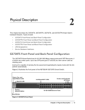
... Smart Switch. GS728TS Front Panel 10/100/1000M Ethernet Ports Chapter 2. Figure 2 illustrates the front panel of sensing the line speed and negotiating the duplex mode with the link partner automatically. Up to two SFP ports (port 27 and 28) at a time can be used as stacking ports. Power, Fan, and Stack Master LEDs Stack ID LED Link/Speed/ACT LEDs Combo and Dedicated SFP Ports Factory Defaults Button Reset Button Figure 2. Physical Description 2 This chapter describes the GS728TS, GS728TPS, GS752TS, and GS752TPS Smart Switch hardware...
... Smart Switch. GS728TS Front Panel 10/100/1000M Ethernet Ports Chapter 2. Figure 2 illustrates the front panel of sensing the line speed and negotiating the duplex mode with the link partner automatically. Up to two SFP ports (port 27 and 28) at a time can be used as stacking ports. Power, Fan, and Stack Master LEDs Stack ID LED Link/Speed/ACT LEDs Combo and Dedicated SFP Ports Factory Defaults Button Reset Button Figure 2. Physical Description 2 This chapter describes the GS728TS, GS728TPS, GS752TS, and GS752TPS Smart Switch hardware...
GS7xxTS-TPS Hardware Installation Guide
Page 15
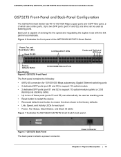
GS728TS, GS728TPS, GS752TS, and GS752TPS Smart Switch Hardware Installation Guide GS752TS Front-Panel and Back-Panel Configuration The GS752TS Smart Switch has 48 10/100/1000 Mbps copper ports and 6 SFP fiber ports, 2 of the NETGEAR GS752TS Smart Switch. Power Connector Chapter 2. Figure 7. Power, Fan, and Stack Master LEDs Stack ID LED Link/Speed/ACT LEDs Combo and Dedicated SFP Ports Factory Defaults Button 10/100/1000M Ethernet Ports Reset Button Figure 6. GS752TS Back Panel The back panel contains a power connector. Physical Description | 15 Figure 6 illustrates the front ...
GS728TS, GS728TPS, GS752TS, and GS752TPS Smart Switch Hardware Installation Guide GS752TS Front-Panel and Back-Panel Configuration The GS752TS Smart Switch has 48 10/100/1000 Mbps copper ports and 6 SFP fiber ports, 2 of the NETGEAR GS752TS Smart Switch. Power Connector Chapter 2. Figure 7. Power, Fan, and Stack Master LEDs Stack ID LED Link/Speed/ACT LEDs Combo and Dedicated SFP Ports Factory Defaults Button 10/100/1000M Ethernet Ports Reset Button Figure 6. GS752TS Back Panel The back panel contains a power connector. Physical Description | 15 Figure 6 illustrates the front ...
GS7xxTS-TPS Hardware Installation Guide
Page 16
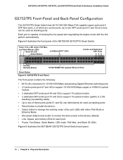
... optical module. • 2 dedicated SFP ports (port 51 and 52) to support 1G optical module (uplink) or 2.5G stacking (via stacking cable). • Up to change the working mode of these ports (ports 51 and 52) can be used as stacking ports. Power, Fan, LED mode, PoE Max, and Stack Master LEDs Stack ID LED Select Button Link/Speed/ACT LEDs Combo and Dedicated SFP Ports Factory Defaults Button 10/100/1000M PoE capable Ethernet Ports Reset Button Figure 8. Up to two SFP ports (port 51 and 52) at a time can alternatively be used as stacking ports • Reset button...
... optical module. • 2 dedicated SFP ports (port 51 and 52) to support 1G optical module (uplink) or 2.5G stacking (via stacking cable). • Up to change the working mode of these ports (ports 51 and 52) can be used as stacking ports. Power, Fan, LED mode, PoE Max, and Stack Master LEDs Stack ID LED Select Button Link/Speed/ACT LEDs Combo and Dedicated SFP Ports Factory Defaults Button 10/100/1000M PoE capable Ethernet Ports Reset Button Figure 8. Up to two SFP ports (port 51 and 52) at a time can alternatively be used as stacking ports • Reset button...
GS7xxTS-TPS Hardware Installation Guide
Page 32
... software driver has been installed. In North America, call 1-888-NETGEAR. Auto-Negotiation The RJ-45 ports negotiate the correct duplex mode, speed, and flow control if the device at a time. A network loop (redundant path) has been created. Ensure that there is linked to the Smart Switch Software Administration Manual for information about using the Web interface. Remove the unit from the switch and then reapply AC power. Use the Web Management to half-duplex. 32 | Appendix : Troubleshooting To reset the switch, remove...
... software driver has been installed. In North America, call 1-888-NETGEAR. Auto-Negotiation The RJ-45 ports negotiate the correct duplex mode, speed, and flow control if the device at a time. A network loop (redundant path) has been created. Ensure that there is linked to the Smart Switch Software Administration Manual for information about using the Web interface. Remove the unit from the switch and then reapply AC power. Use the Web Management to half-duplex. 32 | Appendix : Troubleshooting To reset the switch, remove...

GS7xxTS-TPS Hardware Installation Guide
Page 34
... Mbps copper ports or 1G/100M optical module • 2 x SFP (slot) to support 1G optical module. • 2 x SFP (slot) to support 1G optical module (uplink) and 2.5G stacking (via stacking cable). LEDs Per RJ-45 port: Speed/Link/Activity Per SFP port: Speed/Link/Activity Per device: Power, Fan, Stack Master, Stack ID Per device (for GS7xxTPS): LED mode and PoE Max 34 | Appendix : Technical Specifications Jumbo Frame Support (9K) IPv6 Management, Multicast, and QoS Static Routing MLD Snooping DHCP Snooping Protocol and MAC based VLAN DoS and Auto DoS prevention ACLs (MAC, IPv4...
... Mbps copper ports or 1G/100M optical module • 2 x SFP (slot) to support 1G optical module. • 2 x SFP (slot) to support 1G optical module (uplink) and 2.5G stacking (via stacking cable). LEDs Per RJ-45 port: Speed/Link/Activity Per SFP port: Speed/Link/Activity Per device: Power, Fan, Stack Master, Stack ID Per device (for GS7xxTPS): LED mode and PoE Max 34 | Appendix : Technical Specifications Jumbo Frame Support (9K) IPv6 Management, Multicast, and QoS Static Routing MLD Snooping DHCP Snooping Protocol and MAC based VLAN DoS and Auto DoS prevention ACLs (MAC, IPv4...
GS7xxTS-TPS Installation Guide
Page 1
... and Hardware Installation Guide. (A link to run the utility and view this screen. 2. Click Discover to your switch in the network. Run the Setup program to configure the switch. 2. To configure the switch before connecting it to find your network: 1. Power on the same subnet as the switch. Set up the PC with an RJ-45 connector to your network. Use category 5 (Cat5) unshielded twisted-pair (UTP) cable terminated with a Static IP address...
... and Hardware Installation Guide. (A link to run the utility and view this screen. 2. Click Discover to your switch in the network. Run the Setup program to configure the switch. 2. To configure the switch before connecting it to find your network: 1. Power on the same subnet as the switch. Set up the PC with an RJ-45 connector to your network. Use category 5 (Cat5) unshielded twisted-pair (UTP) cable terminated with a Static IP address...
GS7xxTS-TPS Installation Guide
Page 2
... http://support.netgear.com/app/answers/detail/a_id/2649 WARNING!! If there are trademarks and/or registered trademarks of password in drawers. Next, turn on computer connected to the switch with a securely plugged in accordance with this sequence. For each powered on the switch and wait two minutes. This symbol was placed in Ethernet cable, the corresponding switch LAN port status light will display the switch settings...
... http://support.netgear.com/app/answers/detail/a_id/2649 WARNING!! If there are trademarks and/or registered trademarks of password in drawers. Next, turn on computer connected to the switch with a securely plugged in accordance with this sequence. For each powered on the switch and wait two minutes. This symbol was placed in Ethernet cable, the corresponding switch LAN port status light will display the switch settings...

GS7xxTS-TPS Software Admin Manual
Page 7
... Port Mirroring 278 Multiple Port Mirroring 278 Chapter 8 Maintaining the System Reset 280 Device Reboot 280 Factory Default 281 Upload File From Switch 282 TFTP File Upload 282 HTTP File Upload 283 Download File To Switch 284 TFTP File Download 285 HTTP File Download 287 File Management 288 Copy 288 Dual Image Configuration 289 Dual Image Status 291 Troubleshooting 292 Ping 292 Ping IPv6 293 Traceroute 294 Chapter 9 Accessing Help Online Help 296 Support 296 User Guide 297 Registration 298 Appendix A Hardware Specifications...
... Port Mirroring 278 Multiple Port Mirroring 278 Chapter 8 Maintaining the System Reset 280 Device Reboot 280 Factory Default 281 Upload File From Switch 282 TFTP File Upload 282 HTTP File Upload 283 Download File To Switch 284 TFTP File Download 285 HTTP File Download 287 File Management 288 Copy 288 Dual Image Configuration 289 Dual Image Status 291 Troubleshooting 292 Ping 292 Ping IPv6 293 Traceroute 294 Chapter 9 Accessing Help Online Help 296 Support 296 User Guide 297 Registration 298 Appendix A Hardware Specifications...

GS7xxTS-TPS Software Admin Manual
Page 9
... to manage and monitor IP routing. • Chapter 5, Configuring Quality of Service, describes how to manage the Access Control Lists (ACLs), and how to configure Differentiated Services and Class of information about configuring switch security information such as SNMP, DHCP, PoE, and Green Ethernet. Document Organization The GS728TS, GS728TPS, GS752TS, and GS752TPS Smart Switch Software Administration Manual contains the following chapters: • Chapter 1, Getting Started, contains information about performing the initial system configuration and accessing the user interface. •...
... to manage and monitor IP routing. • Chapter 5, Configuring Quality of Service, describes how to manage the Access Control Lists (ACLs), and how to configure Differentiated Services and Class of information about configuring switch security information such as SNMP, DHCP, PoE, and Green Ethernet. Document Organization The GS728TS, GS728TPS, GS752TS, and GS752TPS Smart Switch Software Administration Manual contains the following chapters: • Chapter 1, Getting Started, contains information about performing the initial system configuration and accessing the user interface. •...
GS7xxTS-TPS Software Admin Manual
Page 138
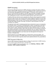
.... To access the IGMP Snooping Configuration page, click Switching> Multicast > IGMP Snooping > IGMP Snooping Configuration. 138 GS728TS, GS728TPS, GS752TS, and GS752TPS Gigabit Smart Switches IGMP Snooping Internet Group Management Protocol (IGMP) Snooping is a feature that allows a switch to forward multicast traffic intelligently on the IGMP query and report messages, the switch forwards traffic only to the ports that request the multicast traffic. When a packet with a broadcast or multicast destination address is received, the switch will forward a copy into different network...
.... To access the IGMP Snooping Configuration page, click Switching> Multicast > IGMP Snooping > IGMP Snooping Configuration. 138 GS728TS, GS728TPS, GS752TS, and GS752TPS Gigabit Smart Switches IGMP Snooping Internet Group Management Protocol (IGMP) Snooping is a feature that allows a switch to forward multicast traffic intelligently on the IGMP query and report messages, the switch forwards traffic only to the ports that request the multicast traffic. When a packet with a broadcast or multicast destination address is received, the switch will forward a copy into different network...

GS7xxTS-TPS Software Admin Manual
Page 141
... configure IGMP Snooping settings for the selected port(s) or LAG(s): • Admin Mode. Select the check box in the Multicast Forwarding Database that were created for a particular group on a particular interface before removing it from the list of time you want the switch to wait for a report for IGMP snooping. The default is 10 seconds. • MRouter Timeout. Enter a value between 2 and 3600 seconds. Configuration changes take effect immediately. IGMP Snooping Table Use the IGMP Snooping Table page to view...
... configure IGMP Snooping settings for the selected port(s) or LAG(s): • Admin Mode. Select the check box in the Multicast Forwarding Database that were created for a particular group on a particular interface before removing it from the list of time you want the switch to wait for a report for IGMP snooping. The default is 10 seconds. • MRouter Timeout. Enter a value between 2 and 3600 seconds. Configuration changes take effect immediately. IGMP Snooping Table Use the IGMP Snooping Table page to view...
GS7xxTS-TPS Software Admin Manual
Page 145
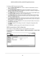
... Querier Admin Mode field, enable or disable the administrative mode for use with the latest information from the switch. GS728TS, GS728TPS, GS752TS, and GS752TPS Gigabit Smart Switches To configure IGMP Snooping Querier settings: 1. Click Cancel to cancel the configuration on the screen and reset the data on which the last querier information is configured on the VLAN on the screen to the switch. To access this page to configure IGMP queriers for IGMP Snooping Querier. 2. The default...
... Querier Admin Mode field, enable or disable the administrative mode for use with the latest information from the switch. GS728TS, GS728TPS, GS752TS, and GS752TPS Gigabit Smart Switches To configure IGMP Snooping Querier settings: 1. Click Cancel to cancel the configuration on the screen and reset the data on which the last querier information is configured on the VLAN on the screen to the switch. To access this page to configure IGMP queriers for IGMP Snooping Querier. 2. The default...
GS7xxTS-TPS Software Admin Manual
Page 149
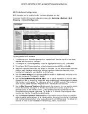
... Snooping settings for a Link Aggregation Group (LAG), click LAGS. 3. The valid range is 0 seconds. The configured value must be greater than Max Response Time. GS728TS, GS728TPS, GS752TS, and GS752TPS Gigabit Smart Switches MLD Interface Configuration MLD snooping can select multiple ports and LAGs to apply the same setting to 3600) seconds. Use the Admin Mode menu to specify whether to wait after sending a query on an interface because it from the list of the stack...
... Snooping settings for a Link Aggregation Group (LAG), click LAGS. 3. The valid range is 0 seconds. The configured value must be greater than Max Response Time. GS728TS, GS728TPS, GS752TS, and GS752TPS Gigabit Smart Switches MLD Interface Configuration MLD snooping can select multiple ports and LAGs to apply the same setting to 3600) seconds. Use the Admin Mode menu to specify whether to wait after sending a query on an interface because it from the list of the stack...
GS7xxTS-TPS Software Admin Manual
Page 152
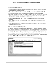
...to cancel the configuration on the screen and reset the data on the screen to enable or disable Multicast Router on the interface. To access the Multicast Router VLAN Configuration page, click Switching Multicast MLD Snooping Multicast Router Configuration VLAN Configuration. 152 To configure multicast router settings for both physical ports and LAGs, click ALL. 4. Use the Multicast Router field to the latest value of the stack member with the ports to the switch. To configure multicast router settings for a Link Aggregation Group (LAG), click LAGS. 3.
...to cancel the configuration on the screen and reset the data on the screen to enable or disable Multicast Router on the interface. To access the Multicast Router VLAN Configuration page, click Switching Multicast MLD Snooping Multicast Router Configuration VLAN Configuration. 152 To configure multicast router settings for both physical ports and LAGs, click ALL. 4. Use the Multicast Router field to the latest value of the stack member with the ports to the switch. To configure multicast router settings for a Link Aggregation Group (LAG), click LAGS. 3.
GS7xxTS-TPS Software Admin Manual
Page 204
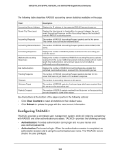
... types are not included as malformed accounting responses. Configuring TACACS+ TACACS+ provides a centralized user management system, while still retaining consistency with RADIUS and other reason. Use the buttons at login. GS728TS, GS728TPS, GS752TS, and GS752TPS Gigabit Smart Switches The following table describes RADIUS accounting server statistics available on the accounting port and dropped for this server that contained invalid authenticators received from this RADIUS accounting server. Packets Dropped The number of RADIUS packets...
... types are not included as malformed accounting responses. Configuring TACACS+ TACACS+ provides a centralized user management system, while still retaining consistency with RADIUS and other reason. Use the buttons at login. GS728TS, GS728TPS, GS752TS, and GS752TPS Gigabit Smart Switches The following table describes RADIUS accounting server statistics available on the accounting port and dropped for this server that contained invalid authenticators received from this RADIUS accounting server. Packets Dropped The number of RADIUS packets...
GS7xxTS-TPS Software Admin Manual
Page 234
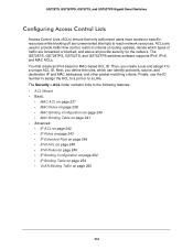
... ACL ID. The GS728TS, GS728TPS, GS752TS, and GS752TPS switches software supports IPv4, IPv6, and MAC ACLs. You first create an IPv4-based or MAC-based ACL ID. The Security > ACL folder contains links to reach network resources. GS728TS, GS728TPS, GS752TS, and GS752TPS Gigabit Smart Switches Configuring Access Control Lists Access Control Lists (ACLs) ensure that only authorized users have access to specific resources while blocking off any unwarranted attempts to the following features: • ACL Wizard • Basic: • MAC ACL...
... ACL ID. The GS728TS, GS728TPS, GS752TS, and GS752TPS switches software supports IPv4, IPv6, and MAC ACLs. You first create an IPv4-based or MAC-based ACL ID. The Security > ACL folder contains links to reach network resources. GS728TS, GS728TPS, GS752TS, and GS752TPS Gigabit Smart Switches Configuring Access Control Lists Access Control Lists (ACLs) ensure that only authorized users have access to specific resources while blocking off any unwarranted attempts to the following features: • ACL Wizard • Basic: • MAC ACL...
GS7xxTS-TPS Software Admin Manual
Page 304
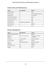
... Boot code update DHCP/manual IP Default gateway System name configuration Configuration save/restore Firmware upgrade Restore defaults Dual image support Factory reset Sets Supported 1 1 1 1 1 1 1 (Web and front-panel button) 1 1 Default N/A DHCP enabled/192.168.0.239 192.168.0.254 NULL N/A N/A N/A Enabled N/A System Management Feature Multi-session Web connections SNMPv1/V2c SNMP v3 Time control LLDP/LLDP-MED Logging MIB support Smart Control Center Statistics Sets Supported 16 Max 5 community entries 1 (Local or SNTP) All ports 3 (Memory/Flash/Server) 1 N/A N/A Default Enabled Enabled...
... Boot code update DHCP/manual IP Default gateway System name configuration Configuration save/restore Firmware upgrade Restore defaults Dual image support Factory reset Sets Supported 1 1 1 1 1 1 1 (Web and front-panel button) 1 1 Default N/A DHCP enabled/192.168.0.239 192.168.0.254 NULL N/A N/A N/A Enabled N/A System Management Feature Multi-session Web connections SNMPv1/V2c SNMP v3 Time control LLDP/LLDP-MED Logging MIB support Smart Control Center Statistics Sets Supported 16 Max 5 community entries 1 (Local or SNTP) All ports 3 (Memory/Flash/Server) 1 N/A N/A Default Enabled Enabled...
GS7xxTS-TPS Software Admin Manual
Page 308
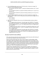
... the default VLAN with VLAN ID 1, specify the following members: port 7 (U) and port 8 (U). • For the VLAN with VLAN ID 10, specify the following members: port 4 (U), port 5 (T), and port 6 (U). 3. They can also be used to provide traffic flow control, restrict contents of routing updates, decide which types of traffic are positioned between two parts of the network to leave port 2 as an untagged packet. • If an untagged packet enters port 4, the switch tags it...
... the default VLAN with VLAN ID 1, specify the following members: port 7 (U) and port 8 (U). • For the VLAN with VLAN ID 10, specify the following members: port 4 (U), port 5 (T), and port 6 (U). 3. They can also be used to provide traffic flow control, restrict contents of routing updates, decide which types of traffic are positioned between two parts of the network to leave port 2 as an untagged packet. • If an untagged packet enters port 4, the switch tags it...


