GS7xxTS-TPS Hardware Installation Guide
Page 3
... Overview 7 Features 7 Stacking 9 Package Contents 10 Chapter 2 Physical Description GS728TS Front-Panel and Back-Panel Configuration 12 GS728TPS Front-Panel and Back-Panel Configuration 13 GS752TS Front-Panel and Back-Panel Configuration 15 GS752TPS Front-Panel and Back-Panel Configuration 16 LED Designations 17 RJ-45 Port LEDs 17 SFP Port LEDs 18 System LEDs 18...
... Overview 7 Features 7 Stacking 9 Package Contents 10 Chapter 2 Physical Description GS728TS Front-Panel and Back-Panel Configuration 12 GS728TPS Front-Panel and Back-Panel Configuration 13 GS752TS Front-Panel and Back-Panel Configuration 15 GS752TPS Front-Panel and Back-Panel Configuration 16 LED Designations 17 RJ-45 Port LEDs 17 SFP Port LEDs 18 System LEDs 18...
GS7xxTS-TPS Hardware Installation Guide
Page 4
GS728TS, GS728TPS, GS752TS, and GS752TPS Smart Switch Hardware Installation Guide Appendix A Troubleshooting Troubleshooting Chart 31 Additional Troubleshooting Suggestions 32 Network Adapter Cards 32 Configuration 32 Switch Integrity 32 Auto-Negotiation 32 Appendix B Technical Specifications Appendix C Notification of Compliance Index 4 | Contents
GS728TS, GS728TPS, GS752TS, and GS752TPS Smart Switch Hardware Installation Guide Appendix A Troubleshooting Troubleshooting Chart 31 Additional Troubleshooting Suggestions 32 Network Adapter Cards 32 Configuration 32 Switch Integrity 32 Auto-Negotiation 32 Appendix B Technical Specifications Appendix C Notification of Compliance Index 4 | Contents

GS7xxTS-TPS Hardware Installation Guide
Page 7
... module. • 2 x SFP (slot) to support 1G optical module. The switch's management features include configuration for port and switch information, VLAN for traffic control, port trunking for 1000M uplink or 2.5 Gbps stacking. The NETGEAR GS728TS, GS728TPS, GS752TS, or GS752TPS Smart Switch can be free standing, stacked with a complete package of features for high-speed...
... module. • 2 x SFP (slot) to support 1G optical module. The switch's management features include configuration for port and switch information, VLAN for traffic control, port trunking for 1000M uplink or 2.5 Gbps stacking. The NETGEAR GS728TS, GS728TPS, GS752TS, or GS752TPS Smart Switch can be free standing, stacked with a complete package of features for high-speed...

GS7xxTS-TPS Hardware Installation Guide
Page 9
... backpressure control. • Per port LEDs and power LED. • Internal open frame power supply. • Standard NETGEAR 7xx series chassis. • NETGEAR Green product series power-saving features: • Automatic power consumption adjustment based on the RJ-45 cable length. •...the remote Slave's low-level drivers, through the Distributed Switching application part that configures and manages all units in which to control and manage the stack. GS728TS, GS728TPS, GS752TS, and GS752TPS Smart Switch Hardware Installation Guide • GS7xxTPS model LEDs: Power and Status LED...
... backpressure control. • Per port LEDs and power LED. • Internal open frame power supply. • Standard NETGEAR 7xx series chassis. • NETGEAR Green product series power-saving features: • Automatic power consumption adjustment based on the RJ-45 cable length. •...the remote Slave's low-level drivers, through the Distributed Switching application part that configures and manages all units in which to control and manage the stack. GS728TS, GS728TPS, GS752TS, and GS752TPS Smart Switch Hardware Installation Guide • GS7xxTPS model LEDs: Power and Status LED...
GS7xxTS-TPS Hardware Installation Guide
Page 10
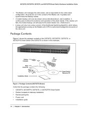
... • Rackmounting kits • Power cord • Installation guide 10 | Chapter 1. Package Contents (GS752TS Shown) Verify that the package contains the following: • GS728TS, GS728TPS, GS752TS, or GS752TPS Smart Switch • Rubber footpads for the entire stack configuration. GS728TS, GS728TPS, GS752TS, and GS752TPS Smart Switch Hardware Installation Guide • The Master unit manages the entire stack...
... • Rackmounting kits • Power cord • Installation guide 10 | Chapter 1. Package Contents (GS752TS Shown) Verify that the package contains the following: • GS728TS, GS728TPS, GS752TS, or GS752TPS Smart Switch • Rubber footpads for the entire stack configuration. GS728TS, GS728TPS, GS752TS, and GS752TPS Smart Switch Hardware Installation Guide • The Master unit manages the entire stack...
GS7xxTS-TPS Hardware Installation Guide
Page 12
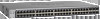
... GS728TS Front-Panel and Back-Panel Configuration • GS728TPS Front-Panel and Back-Panel Configuration • GS752TS Front-Panel and Back-Panel Configuration • GS752TPS Front-Panel and Back-Panel Configuration • LED Designations • ...Device Hardware Interfaces GS728TS Front-Panel and Back-Panel Configuration The GS728TS Smart Switch has 24 10/100/1000 Mbps copper ports and 6 SFP fiber ports, 2 of the NETGEAR...
... GS728TS Front-Panel and Back-Panel Configuration • GS728TPS Front-Panel and Back-Panel Configuration • GS752TS Front-Panel and Back-Panel Configuration • GS752TPS Front-Panel and Back-Panel Configuration • LED Designations • ...Device Hardware Interfaces GS728TS Front-Panel and Back-Panel Configuration The GS728TS Smart Switch has 24 10/100/1000 Mbps copper ports and 6 SFP fiber ports, 2 of the NETGEAR...
GS7xxTS-TPS Hardware Installation Guide
Page 13
... duplex mode with the link partner automatically. Each port is capable of the NETGEAR GS728TPS Smart Switch. GS728TS, GS728TPS, GS752TS, and GS752TPS Smart Switch Hardware Installation Guide The front panel contains the following: • ...24 RJ-45 connectors for each port. • Power, Fan Status, Stack Master, and Stack ID LEDs. GS728TS Back Panel The back panel contains a power connector. Figure 3. Power Connector GS728TPS Front-Panel and Back-Panel Configuration...
... duplex mode with the link partner automatically. Each port is capable of the NETGEAR GS728TPS Smart Switch. GS728TS, GS728TPS, GS752TS, and GS752TPS Smart Switch Hardware Installation Guide The front panel contains the following: • ...24 RJ-45 connectors for each port. • Power, Fan Status, Stack Master, and Stack ID LEDs. GS728TS Back Panel The back panel contains a power connector. Figure 3. Power Connector GS728TPS Front-Panel and Back-Panel Configuration...
GS7xxTS-TPS Hardware Installation Guide
Page 15
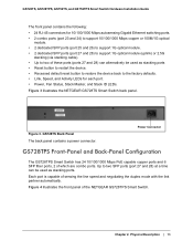
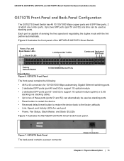
... Factory Defaults Button 10/100/1000M Ethernet Ports Reset Button Figure 6. Each port is capable of the NETGEAR GS752TS Smart Switch. Power Connector Chapter 2. GS752TS Front Panel The front panel contains the following: • 48 RJ-45 connectors for each port &#... NETGEAR GS752TS Smart Switch back panel. Figure 6 illustrates the front panel of sensing the line speed and negotiating the duplex mode with the link partner automatically. GS728TS, GS728TPS, GS752TS, and GS752TPS Smart Switch Hardware Installation Guide GS752TS Front-Panel and Back-Panel Configuration The GS752TS ...
... Factory Defaults Button 10/100/1000M Ethernet Ports Reset Button Figure 6. Each port is capable of the NETGEAR GS752TS Smart Switch. Power Connector Chapter 2. GS752TS Front Panel The front panel contains the following: • 48 RJ-45 connectors for each port &#... NETGEAR GS752TS Smart Switch back panel. Figure 6 illustrates the front panel of sensing the line speed and negotiating the duplex mode with the link partner automatically. GS728TS, GS728TPS, GS752TS, and GS752TPS Smart Switch Hardware Installation Guide GS752TS Front-Panel and Back-Panel Configuration The GS752TS ...
GS7xxTS-TPS Hardware Installation Guide
Page 16
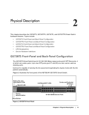
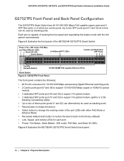
...Physical Description GS728TS, GS728TPS, GS752TS, and GS752TPS Smart Switch Hardware Installation Guide GS752TPS Front-Panel and Back-Panel Configuration The GS752TPS Smart Switch has 48 10/100/1000 Mbps PoE capable copper ports and 6 SFP fiber ports, 2 of the NETGEAR GS752TPS Smart Switch. GS752TPS Front Panel The front panel..., and Stack ID LEDs. Each port is capable of the port LEDs with the link partner automatically. Figure 9 illustrates the NETGEAR GS752TPS Smart Switch back panel. 16 | Chapter 2. Up to the factory defaults • Link, Speed, and Activity LEDs for ...
...Physical Description GS728TS, GS728TPS, GS752TS, and GS752TPS Smart Switch Hardware Installation Guide GS752TPS Front-Panel and Back-Panel Configuration The GS752TPS Smart Switch has 48 10/100/1000 Mbps PoE capable copper ports and 6 SFP fiber ports, 2 of the NETGEAR GS752TPS Smart Switch. GS752TPS Front Panel The front panel..., and Stack ID LEDs. Each port is capable of the port LEDs with the link partner automatically. Figure 9 illustrates the NETGEAR GS752TPS Smart Switch back panel. 16 | Chapter 2. Up to the factory defaults • Link, Speed, and Activity LEDs for ...
GS7xxTS-TPS Hardware Installation Guide
Page 19
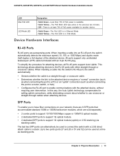
... attached device, without requiring user intervention. There is at a time as when connecting the port to a router, switch, or hub). • Configures the RJ-45 port to enable communications with a 2.5G direct attach cable to support 1G optical module (uplink) or 2.5G stacking (via stacking cable...attached device. SFP Ports To enable you to a PC) or an "uplink" connection (such as stacking ports. Chapter 2. GS728TS, GS728TPS, GS752TS, and GS752TPS Smart Switch Hardware Installation Guide LED Max PoE LED LED Mode LED Designation • Solid Green -Less than 7W of PoE power is in PoE...
... attached device, without requiring user intervention. There is at a time as when connecting the port to a router, switch, or hub). • Configures the RJ-45 port to enable communications with a 2.5G direct attach cable to support 1G optical module (uplink) or 2.5G stacking (via stacking cable...attached device. SFP Ports To enable you to a PC) or an "uplink" connection (such as stacking ports. Chapter 2. GS728TS, GS728TPS, GS752TS, and GS752TPS Smart Switch Hardware Installation Guide LED Max PoE LED LED Mode LED Designation • Solid Green -Less than 7W of PoE power is in PoE...

GS7xxTS-TPS Hardware Installation Guide
Page 20
...recommended to press the button for over two seconds. You need to be used as the switch performs its factory settings. The last saved configuration is equivalent to powering the unit off and back on the front panel to its Power On Self Test (POST). Factory Defaults Button The... a LED Mode Select button on the front panel so that you can change the LED mode. 20 | Chapter 2. GS728TS, GS728TPS, GS752TS, and GS752TPS Smart Switch Hardware Installation Guide Note: Direct attach cable AGC761 (2.5G) is sold separately. Reset Button The Smart Switch has a Reset button on . ...
...recommended to press the button for over two seconds. You need to be used as the switch performs its factory settings. The last saved configuration is equivalent to powering the unit off and back on the front panel to its Power On Self Test (POST). Factory Defaults Button The... a LED Mode Select button on the front panel so that you can change the LED mode. 20 | Chapter 2. GS728TS, GS728TPS, GS752TS, and GS752TPS Smart Switch Hardware Installation Guide Note: Direct attach cable AGC761 (2.5G) is sold separately. Reset Button The Smart Switch has a Reset button on . ...
GS7xxTS-TPS Hardware Installation Guide
Page 22
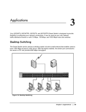
With full-duplex enabled, the switch port connected to provide flexibility in configuring your only network traffic-distribution device or with 10 Mbps, 100 Mbps, and 1000 Mbps hubs and switches. It can be used as your network ... 47 48 49F 50F GS752TXS 51F 52F SFP + Reset Factory Defaults Green=10G Link Yellow=1G Blink=ACT ` ` ` ` Figure 10. Applications 3 Your GS728TS, GS728TPS, GS752TS, and GS752TPS Smart Switch is designed to the server or PC can provide 2000 Mbps throughput. Desktop Switching The Smart Switch can be used as a desktop switch...
With full-duplex enabled, the switch port connected to provide flexibility in configuring your only network traffic-distribution device or with 10 Mbps, 100 Mbps, and 1000 Mbps hubs and switches. It can be used as your network ... 47 48 49F 50F GS752TXS 51F 52F SFP + Reset Factory Defaults Green=10G Link Yellow=1G Blink=ACT ` ` ` ` Figure 10. Applications 3 Your GS728TS, GS728TPS, GS752TS, and GS752TPS Smart Switch is designed to the server or PC can provide 2000 Mbps throughput. Desktop Switching The Smart Switch can be used as a desktop switch...
GS7xxTS-TPS Hardware Installation Guide
Page 28
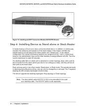
...above. If the master unit fails, the master-backup unit will set all their ports to assign different unit IDs. In the default configuration, the master and backup switches are assigned unit ID 1 and 2, respectively; Each unit may use the Web interface to the down ... cable is under 30 seconds. Installing and SFP Transceiver Module (GS752TPS Shown) Step 6: Installing Device as Stand-alone or Stack Master A master-backup unit runs as a slave unit as a stacking cable. GS728TS, GS728TPS, GS752TS, and GS752TPS Smart Switch Hardware Installation Guide Figure 14. The device supports two...
...above. If the master unit fails, the master-backup unit will set all their ports to assign different unit IDs. In the default configuration, the master and backup switches are assigned unit ID 1 and 2, respectively; Each unit may use the Web interface to the down ... cable is under 30 seconds. Installing and SFP Transceiver Module (GS752TPS Shown) Step 6: Installing Device as Stand-alone or Stack Master A master-backup unit runs as a slave unit as a stacking cable. GS728TS, GS728TPS, GS752TS, and GS752TPS Smart Switch Hardware Installation Guide Figure 14. The device supports two...
GS7xxTS-TPS Hardware Installation Guide
Page 29
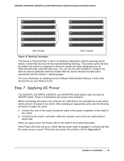
...can use the following procedure to select a particular switch as a wall socket or power strip. Step 7: Applying AC Power The GS728TS, GS728TPS, GS752TS, and GS752TPS Smart Switch does not have an ON/OFF switch. Power is plugged in terms of the switch. 2. A link to this does not resolve ... page). If the Power LED does not go on, check that is operational (see the Software Administration Manual. If this document is configured to allow the master and slave designations to Appendix A. GS728TS, GS728TPS, GS752TS, and GS752TPS Smart Switch Hardware Installation Guide Figure 15.
...can use the following procedure to select a particular switch as a wall socket or power strip. Step 7: Applying AC Power The GS728TS, GS728TPS, GS752TS, and GS752TPS Smart Switch does not have an ON/OFF switch. Power is plugged in terms of the switch. 2. A link to this does not resolve ... page). If the Power LED does not go on, check that is operational (see the Software Administration Manual. If this document is configured to allow the master and slave designations to Appendix A. GS728TS, GS728TPS, GS752TS, and GS752TPS Smart Switch Hardware Installation Guide Figure 15.

GS7xxTS-TPS Hardware Installation Guide
Page 30
... management software is configured with a default IP address of 192.168.0.239 and a subnet mask of the network. For more information about managing the switch, see the Software Administration Manual on the Smart Switch Resource CD. Installation GS728TS, GS728TPS, GS752TS, and GS752TPS Smart Switch Hardware ...using the management software. The ports can be used without using a Web Browser or the PC Utility The GS728TS, GS728TPS, GS752TS, and GS752TPS Smart Switch contains software for the switch to work. However, the management software enables the setup of VLAN and trunking features...
... management software is configured with a default IP address of 192.168.0.239 and a subnet mask of the network. For more information about managing the switch, see the Software Administration Manual on the Smart Switch Resource CD. Installation GS728TS, GS728TPS, GS752TS, and GS752TPS Smart Switch Hardware ...using the management software. The ports can be used without using a Web Browser or the PC Utility The GS728TS, GS728TPS, GS752TS, and GS752TPS Smart Switch contains software for the switch to work. However, the management software enables the setup of VLAN and trunking features...
GS7xxTS-TPS Hardware Installation Guide
Page 32
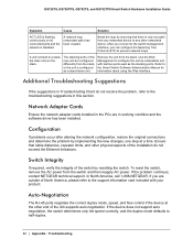
...NETGEAR technical support. A unit is only one step at the other physical aspects of the new unit are configured differently from the stack. Additional Troubleshooting Suggestions If the suggestions in Troubleshooting Chart do not exceed the Ethernet limitations. GS728TS, GS728TPS, GS752TS, and GS752TPS... Smart Switch Hardware Installation Guide Symptom Cause Solution ACT LED is flashing continuously on all connected ports and the network is configured as a stand-alone unit. After you ...
...NETGEAR technical support. A unit is only one step at the other physical aspects of the new unit are configured differently from the stack. Additional Troubleshooting Suggestions If the suggestions in Troubleshooting Chart do not exceed the Ethernet limitations. GS728TS, GS728TPS, GS752TS, and GS752TPS... Smart Switch Hardware Installation Guide Symptom Cause Solution ACT LED is flashing continuously on all connected ports and the network is configured as a stand-alone unit. After you ...
GS7xxTS-TPS Installation Guide
Page 1
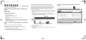
.... GS7xxTS-TPS IG 21Nov11.book Page 1 Thursday, December 1, 2011 12:03 PM Installation Guide NETGEAR GS728TS, GS728TPS, GS752TS, GS752TPS Smart Switch™ Start Here Verify Package Contents • NETGEAR Smart Switch • Rubber footpads for tabletop installation • Power cord • Rack-mount ...switch. 5. Connect each PC to run the utility and view this screen. 2. Power on the switch front panel. To configure the switch before connecting it to the online Software Administration Manual is on a PC 1. Verify that includes the Smart Control Center...
.... GS7xxTS-TPS IG 21Nov11.book Page 1 Thursday, December 1, 2011 12:03 PM Installation Guide NETGEAR GS728TS, GS728TPS, GS752TS, GS752TPS Smart Switch™ Start Here Verify Package Contents • NETGEAR Smart Switch • Rubber footpads for tabletop installation • Power cord • Rack-mount ...switch. 5. Connect each PC to run the utility and view this screen. 2. Power on the switch front panel. To configure the switch before connecting it to the online Software Administration Manual is on a PC 1. Verify that includes the Smart Control Center...
GS7xxTS-TPS Software Admin Manual
Page 4
GS728TS, GS728TPS, GS752TS, and GS752TPS Gigabit Smart Switches PoE/PoE+ (GS728TPS and GS752TPS Only 70 PoE Configuration 70 PoE Port Configuration 72 SNMP 75 SNMPv1/v2 75 Trap Configuration 77 Trap Flags 78 SNMP Supported MIBs 79 SNMP v3 User Configuration 79 LLDP 80 LLDP Configuration 81 LLDP Port Settings 82 LLDP-MED Network Policy 83 LLDP-MED Port...
GS728TS, GS728TPS, GS752TS, and GS752TPS Gigabit Smart Switches PoE/PoE+ (GS728TPS and GS752TPS Only 70 PoE Configuration 70 PoE Port Configuration 72 SNMP 75 SNMPv1/v2 75 Trap Configuration 77 Trap Flags 78 SNMP Supported MIBs 79 SNMP v3 User Configuration 79 LLDP 80 LLDP Configuration 81 LLDP Port Settings 82 LLDP-MED Network Policy 83 LLDP-MED Port...
GS7xxTS-TPS Software Admin Manual
Page 5
GS728TS, GS728TPS, GS752TS, and GS752TPS Gigabit Smart Switches Spanning Tree Protocol 122 STP Switch Configuration 123 CST Configuration 125 CST Port Configuration 126 CST Port Status 128 Rapid STP 129 MST Configuration 130 MST Port Configuration 131 STP Statistics 134 Multicast 135 MFDB 135 Auto-Video Configuration 137 IGMP Snooping 138 IGMP Snooping Querier 144 MLD Snooping 147 Forwarding...
GS728TS, GS728TPS, GS752TS, and GS752TPS Gigabit Smart Switches Spanning Tree Protocol 122 STP Switch Configuration 123 CST Configuration 125 CST Port Configuration 126 CST Port Status 128 Rapid STP 129 MST Configuration 130 MST Port Configuration 131 STP Statistics 134 Multicast 135 MFDB 135 Auto-Video Configuration 137 IGMP Snooping 138 IGMP Snooping Querier 144 MLD Snooping 147 Forwarding...
GS7xxTS-TPS Software Admin Manual
Page 6
GS728TS, GS728TPS, GS752TS, and GS752TPS Gigabit Smart Switches IPv6 Class Configuration 189 Policy Configuration 191 Service Configuration 195 Service Statistics 196 Chapter 6 Managing Device Security Management Security Settings 197 Change Password 198 RADIUS Configuration 199 Configuring TACACS 204 Authentication List Configuration 207 Configuring Management Access 210 HTTP Configuration 211 Secure HTTP Configuration 212 Certificate Management 213 Certificate Download 214 Access Profile Configuration 215...
GS728TS, GS728TPS, GS752TS, and GS752TPS Gigabit Smart Switches IPv6 Class Configuration 189 Policy Configuration 191 Service Configuration 195 Service Statistics 196 Chapter 6 Managing Device Security Management Security Settings 197 Change Password 198 RADIUS Configuration 199 Configuring TACACS 204 Authentication List Configuration 207 Configuring Management Access 210 HTTP Configuration 211 Secure HTTP Configuration 212 Certificate Management 213 Certificate Download 214 Access Profile Configuration 215...


