FSM726E Hardware Installation Guide
Page 2
NETGEAR, INC. E-mail: support@netgear.com North American NETGEAR website: http://www.netgear.com Trademarks NETGEAR, the NETGEAR logo, ProSafe, and Auto Uplink are registered trademarks or trademarks of their respective holders. Voluntary Control Council for compliance with your product. Certificate of the product(s) or circuit layout(s) described herein. Technical Support Please refer to certain restrictions. Support Information Phone: 1-888-NETGEAR, for example, test transmitters) in which case, the...
NETGEAR, INC. E-mail: support@netgear.com North American NETGEAR website: http://www.netgear.com Trademarks NETGEAR, the NETGEAR logo, ProSafe, and Auto Uplink are registered trademarks or trademarks of their respective holders. Voluntary Control Council for compliance with your product. Certificate of the product(s) or circuit layout(s) described herein. Technical Support Please refer to certain restrictions. Support Information Phone: 1-888-NETGEAR, for example, test transmitters) in which case, the...
FSM726E Hardware Installation Guide
Page 3
...). Customer Support Refer to radio communications. However, there is no guarantee that may cause harmful interference to the Support Information Card that the NETGEAR ProSafe 24-Port Ethernet L2 Managed Switch Model FSM726E is declared by the application of Communications. Règlement sur le brouillage radioélectrique du ministère des Communications Cet appareil numérique (NETGEAR ProSafe 24-Port Ethernet L2 Managed Switch Model FSM726E) respecte...
...). Customer Support Refer to radio communications. However, there is no guarantee that may cause harmful interference to the Support Information Card that the NETGEAR ProSafe 24-Port Ethernet L2 Managed Switch Model FSM726E is declared by the application of Communications. Règlement sur le brouillage radioélectrique du ministère des Communications Cet appareil numérique (NETGEAR ProSafe 24-Port Ethernet L2 Managed Switch Model FSM726E) respecte...
FSM726E Hardware Installation Guide
Page 6
Managed Layer 2 Switch with 2 Gigabit Ethernet Ports FSM726E Hardware Installation Guide Appendix A Factory Default Settings and Technical Specifications Factory Default Settings A-1 Technical Specifications A-2 vi v1.0, November 2008
Managed Layer 2 Switch with 2 Gigabit Ethernet Ports FSM726E Hardware Installation Guide Appendix A Factory Default Settings and Technical Specifications Factory Default Settings A-1 Technical Specifications A-2 vi v1.0, November 2008
FSM726E Hardware Installation Guide
Page 7
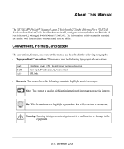
... with 2 Gigabit Ethernet Ports FSM726E Hardware Installation Guide describes how to highlight a procedure that will save time or resources. This manual uses the following typographical conventions: Italic Bold italic Emphasis, books, CDs, file and server names, extensions User input, IP addresses, GUI screen text URL links • Formats. Warning: Ignoring this type of this manual is used to the equipment. 1 v1.0, November 2008 About This Manual The NETGEAR® ProSafe® Managed Layer 2 Switch with...
... with 2 Gigabit Ethernet Ports FSM726E Hardware Installation Guide describes how to highlight a procedure that will save time or resources. This manual uses the following typographical conventions: Italic Bold italic Emphasis, books, CDs, file and server names, extensions User input, IP addresses, GUI screen text URL links • Formats. Warning: Ignoring this type of this manual is used to the equipment. 1 v1.0, November 2008 About This Manual The NETGEAR® ProSafe® Managed Layer 2 Switch with...
FSM726E Hardware Installation Guide
Page 8
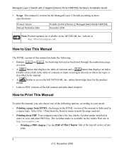
... the Managed Layer 2 Switch according to these specifications: Product Version Manual Publication Date ProSafe 24-Port Ethernet L2 Managed Switch Model FSM726E November 2008 Note: Product updates are available on the Adobe Web site at a time. , for the product model. • Links to Use This Manual The HTML version of this manual, you can choose one page •A button that displays the table of the full manual and individual chapters. Managed Layer 2 Switch with 2 Gigabit Ethernet Ports FSM726E Hardware Installation Guide • Scope. How to PDF versions...
... the Managed Layer 2 Switch according to these specifications: Product Version Manual Publication Date ProSafe 24-Port Ethernet L2 Managed Switch Model FSM726E November 2008 Note: Product updates are available on the Adobe Web site at a time. , for the product model. • Links to Use This Manual The HTML version of this manual, you can choose one page •A button that displays the table of the full manual and individual chapters. Managed Layer 2 Switch with 2 Gigabit Ethernet Ports FSM726E Hardware Installation Guide • Scope. How to PDF versions...
FSM726E Hardware Installation Guide
Page 9
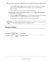
...; Click the Complete PDF Manual link at the top left corner of any page in the chapter you can save paper and printer ink by selecting this feature. Revision History Part Number 202-10452-01 Version Number Date 1.0 October 2008 Description Original publication. 3 v1.0, November 2008 Managed Layer 2 Switch with 2 Gigabit Ethernet Ports FSM726E Hardware Installation Guide • Click the PDF of This Chapter link at the top left...
...; Click the Complete PDF Manual link at the top left corner of any page in the chapter you can save paper and printer ink by selecting this feature. Revision History Part Number 202-10452-01 Version Number Date 1.0 October 2008 Description Original publication. 3 v1.0, November 2008 Managed Layer 2 Switch with 2 Gigabit Ethernet Ports FSM726E Hardware Installation Guide • Click the PDF of This Chapter link at the top left...
FSM726E Hardware Installation Guide
Page 11
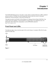
... ProSafe 24-Port Ethernet L2 Managed Switch Model FSM726E. The switch can use to eliminate bottlenecks, boost performance, and increase productivity. It includes powerful management features that you can be free-standing, or rack-mounted in a wiring closet or an equipment room. Chapter 1 Introduction The NETGEAR Managed Layer 2 Switch is a state-of the switch chassis. For information about features for each product, see the NETGEAR website at http://www.netgear.com...
... ProSafe 24-Port Ethernet L2 Managed Switch Model FSM726E. The switch can use to eliminate bottlenecks, boost performance, and increase productivity. It includes powerful management features that you can be free-standing, or rack-mounted in a wiring closet or an equipment room. Chapter 1 Introduction The NETGEAR Managed Layer 2 Switch is a state-of the switch chassis. For information about features for each product, see the NETGEAR website at http://www.netgear.com...
FSM726E Hardware Installation Guide
Page 12
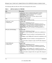
Power is supplied and the switch is booting up. • Blinking yellow. System is working. • Blinking green. Power is operating normally. Link/ACT LED • Off. The port is sending or receiving packets at 1000 Mbps. • Solid Yellow. Managed Layer 2 Switch with 2 Gigabit Ethernet Ports FSM726E Hardware Installation Guide The following table describes the LEDs on this port. • Solid green. The fan has failed. • Green. Link/ACT LED • Off: No link is changed to fiber, the copper LEDs changes to Off status. 1-2 Introduction v1...
Power is supplied and the switch is booting up. • Blinking yellow. System is working. • Blinking green. Power is operating normally. Link/ACT LED • Off. The port is sending or receiving packets at 1000 Mbps. • Solid Yellow. Managed Layer 2 Switch with 2 Gigabit Ethernet Ports FSM726E Hardware Installation Guide The following table describes the LEDs on this port. • Solid green. The fan has failed. • Green. Link/ACT LED • Off: No link is changed to fiber, the copper LEDs changes to Off status. 1-2 Introduction v1...
FSM726E Hardware Installation Guide
Page 13
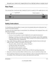
... or removing covers that are marked with the triangular symbol with 2 Gigabit Ethernet Ports FSM726E Hardware Installation Guide Rear Panel The rear panel has a console port and a standard AC power receptacle for the supplied power cord. The product has been exposed to the equipment, observe the following conditions occur, unplug the product from the electrical outlet and replace the part, or contact your system documentation. - The...
... or removing covers that are marked with the triangular symbol with 2 Gigabit Ethernet Ports FSM726E Hardware Installation Guide Rear Panel The rear panel has a console port and a standard AC power receptacle for the supplied power cord. The product has been exposed to the equipment, observe the following conditions occur, unplug the product from the electrical outlet and replace the part, or contact your system documentation. - The...

FSM726E Hardware Installation Guide
Page 14
... any AC powered option intended for use in electrical power, use a surge suppressor, line conditioner, or uninterruptible power supply (UPS). • Position system cables and power cables carefully; Be sure that they cannot be sure that attached devices are electrically rated to operate with the power available in most of your country. Managed Layer 2 Switch with three-prong plugs to help ensure proper grounding. route cables so...
... any AC powered option intended for use in electrical power, use a surge suppressor, line conditioner, or uninterruptible power supply (UPS). • Position system cables and power cables carefully; Be sure that they cannot be sure that attached devices are electrically rated to operate with the power available in most of your country. Managed Layer 2 Switch with three-prong plugs to help ensure proper grounding. route cables so...
FSM726E Hardware Installation Guide
Page 15
Introduction 1-5 v1.0, November 2008 Consult a licensed electrician or your power company for site modifications. • Always follow your local and national wiring rules. • Move products with 2 Gigabit Ethernet Ports FSM726E Hardware Installation Guide • Do not modify power cables or plugs. ensure that all casters and stabilizers are firmly connected to the system. Avoid sudden stops and uneven surfaces. Managed Layer 2 Switch with care;
Introduction 1-5 v1.0, November 2008 Consult a licensed electrician or your power company for site modifications. • Always follow your local and national wiring rules. • Move products with 2 Gigabit Ethernet Ports FSM726E Hardware Installation Guide • Do not modify power cables or plugs. ensure that all casters and stabilizers are firmly connected to the system. Avoid sudden stops and uneven surfaces. Managed Layer 2 Switch with care;
FSM726E Hardware Installation Guide
Page 19
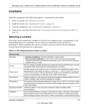
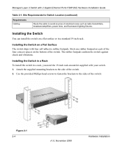
... 2 inches (5.08 centimeters) free on page 2-5 4. Managed Layer 2 Switch with 2 Gigabit Ethernet Ports FSM726E Hardware Installation Guide Installation Install the equipment in the following site requirements. Site Requirements for the switch are shown in Appendix A, "Factory Default Settings and Technical Specifications. See "Checking the Installation" on all sides for cooling. Be sure that lets you access the front panel RJ-45 ports, view the front panel LEDs, and access the rear-panel power connector. Select a Location.
... 2 inches (5.08 centimeters) free on page 2-5 4. Managed Layer 2 Switch with 2 Gigabit Ethernet Ports FSM726E Hardware Installation Guide Installation Install the equipment in the following site requirements. Site Requirements for the switch are shown in Appendix A, "Factory Default Settings and Technical Specifications. See "Checking the Installation" on all sides for cooling. Be sure that lets you access the front panel RJ-45 ports, view the front panel LEDs, and access the rear-panel power connector. Select a Location.
FSM726E Hardware Installation Guide
Page 20
... 2 Gigabit Ethernet Ports FSM726E Hardware Installation Guide Table 2-1. Installing the Switch You can install the switch on a flat surface or in a rack, you need the 19-inch rack-mount kit supplied with your switch. 1. Installing the Switch in a Rack To install the switch in a standard 19-inch rack. Attach the supplied mounting brackets to the side of the switch. Stick one rubber footpad on each of electrical noise such as radio transmitters, broadcast amplifiers, power lines, and fluorescent lighting...
... 2 Gigabit Ethernet Ports FSM726E Hardware Installation Guide Table 2-1. Installing the Switch You can install the switch on a flat surface or in a rack, you need the 19-inch rack-mount kit supplied with your switch. 1. Installing the Switch in a Rack To install the switch in a standard 19-inch rack. Attach the supplied mounting brackets to the side of the switch. Stick one rubber footpad on each of electrical noise such as radio transmitters, broadcast amplifiers, power lines, and fluorescent lighting...

FSM726E Hardware Installation Guide
Page 21
... LED turns green and the switch is working and ready to ensure that cables are installed correctly. 3. Connecting to connect or disconnect the power cord. The LED should light up , check that the power cable is plugged in correctly and that all equipment is good. Check cable routing to pass data. • If the POST fails, the Power LED blinks yellow. If the Power LED does not light up in the rack. Verify that the power source is mounted...
... LED turns green and the switch is working and ready to ensure that cables are installed correctly. 3. Connecting to connect or disconnect the power cord. The LED should light up , check that the power cable is plugged in correctly and that all equipment is good. Check cable routing to pass data. • If the POST fails, the Power LED blinks yellow. If the Power LED does not light up in the rack. Verify that the power source is mounted...
FSM726E Hardware Installation Guide
Page 23
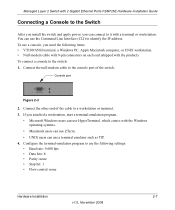
Configure the terminal-emulation program to use a terminal emulator such as TIP. 4. Managed Layer 2 Switch with 2 Gigabit Ethernet Ports FSM726E Hardware Installation Guide Connecting a Console to the Switch After you install the switch and apply power, you need the following settings: • Baud rate: 9,600 bps • Data bits: 8 • Parity: none • Stop bit: 1 • Flow control: none Hardware Installation 2-7 v1.0, November 2008 To use the Command Line Interface (CLI) to it with the product). If you attached a workstation, start a terminal-emulation program...
Configure the terminal-emulation program to use a terminal emulator such as TIP. 4. Managed Layer 2 Switch with 2 Gigabit Ethernet Ports FSM726E Hardware Installation Guide Connecting a Console to the Switch After you install the switch and apply power, you need the following settings: • Baud rate: 9,600 bps • Data bits: 8 • Parity: none • Stop bit: 1 • Flow control: none Hardware Installation 2-7 v1.0, November 2008 To use the Command Line Interface (CLI) to it with the product). If you attached a workstation, start a terminal-emulation program...
FSM726E Hardware Installation Guide
Page 25
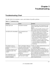
... the port at the connected device. A network loop (redundant path) has been created. Chapter 3 Troubleshooting Troubleshooting Chart The table below lists symptoms, causes, and solutions of the network. See Appendix A, "Factory Default Settings and Technical Specifications. • Check for the switch at the switch and at both the switch and the connecting device. • Make sure that the cabling is disabled. or full-duplex setting on all cables used are correct and comply with Ethernet specifications...
... the port at the connected device. A network loop (redundant path) has been created. Chapter 3 Troubleshooting Troubleshooting Chart The table below lists symptoms, causes, and solutions of the network. See Appendix A, "Factory Default Settings and Technical Specifications. • Check for the switch at the switch and at both the switch and the connecting device. • Make sure that the cabling is disabled. or full-duplex setting on all cables used are correct and comply with Ethernet specifications...
FSM726E Hardware Installation Guide
Page 26
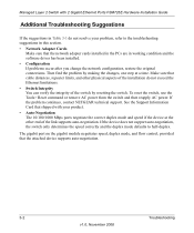
... software driver has been installed. • Configuration If problems occur after you change the network configuration, restore the original connections. If the problem continues, contact NETGEAR technical support. To reset the switch, use the Tools> Reset command or remove AC power from the switch and then reapply AC power. Managed Layer 2 Switch with your problem, refer to half-duplex. The gigabit port on the gigabit module negotiates speed, duplex mode, and flow control, provided that shipped with 2 Gigabit Ethernet Ports FSM726E Hardware Installation Guide Additional...
... software driver has been installed. • Configuration If problems occur after you change the network configuration, restore the original connections. If the problem continues, contact NETGEAR technical support. To reset the switch, use the Tools> Reset command or remove AC power from the switch and then reapply AC power. Managed Layer 2 Switch with your problem, refer to half-duplex. The gigabit port on the gigabit module negotiates speed, duplex mode, and flow control, provided that shipped with 2 Gigabit Ethernet Ports FSM726E Hardware Installation Guide Additional...
FSM726E Hardware Installation Guide
Page 27
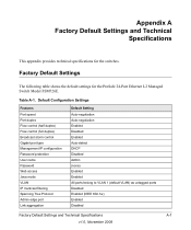
... specifications for the ProSafe 24-Port Ethernet L2 Managed Switch Model FSM726E. Table A-1. Default Configuration Settings Features Port speed Port duplex Flow control (half duplex) Flow control (full duplex) Broadcast storm control Gigabit port type Management IP configuration Password protection User name Password Web access Java mode VLAN IP multicast filtering Spanning Tree Protocol Admin edge port Link aggregation Default Setting Auto-negotiation Auto-negotiation Enabled Disabled Enabled Auto-detect DHCP Disabled Admin (none) Enabled Enabled All ports belong to VLAN 1 (default VLAN...
... specifications for the ProSafe 24-Port Ethernet L2 Managed Switch Model FSM726E. Table A-1. Default Configuration Settings Features Port speed Port duplex Flow control (half duplex) Flow control (full duplex) Broadcast storm control Gigabit port type Management IP configuration Password protection User name Password Web access Java mode VLAN IP multicast filtering Spanning Tree Protocol Admin edge port Link aggregation Default Setting Auto-negotiation Auto-negotiation Enabled Disabled Enabled Auto-detect DHCP Disabled Admin (none) Enabled Enabled All ports belong to VLAN 1 (default VLAN...
FSM726E Hardware Installation Guide
Page 28
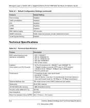
... GMRP MAC address aging SNMP community VLAN Ingress filtering Default Setting Disabled Disabled Disabled Disabled Disabled 300 seconds Public (read-only access), private (read/write access) Enabled Technical Specifications Table A-2. Managed Layer 2 Switch with 2 Gigabit Ethernet Ports FSM726E Hardware Installation Guide Table A-1. Technical Specifications Feature Description IEEE network protocol and standards compatibility • 802.3 10BASE-T • 802.3u 100BASE-TX • 802.3z 1000BASE-SX • 802.3ab 1000BASE-T • 802.3x flow control Interface (Auto Uplink...
... GMRP MAC address aging SNMP community VLAN Ingress filtering Default Setting Disabled Disabled Disabled Disabled Disabled 300 seconds Public (read-only access), private (read/write access) Enabled Technical Specifications Table A-2. Managed Layer 2 Switch with 2 Gigabit Ethernet Ports FSM726E Hardware Installation Guide Table A-1. Technical Specifications Feature Description IEEE network protocol and standards compatibility • 802.3 10BASE-T • 802.3u 100BASE-TX • 802.3z 1000BASE-SX • 802.3ab 1000BASE-T • 802.3x flow control Interface (Auto Uplink...
FSM726E Hardware Installation Guide
Page 29
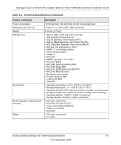
Managed Layer 2 Switch with 2 Gigabit Ethernet Ports FSM726E Hardware Installation Guide Table A-2. Technical Specifications (continued) Feature (continued) Power consumption Dimensions (W x D x H) Weight Management Environment Electromagnetic emissions and immunity Safety Description 15 W maximum 100-240 VAC, 50-60 Hz universal input 17.32 x 8.1 x 1.70 in (440 x 205 x 43.2 mm) 6.15 lbs. (2.79 kg) • 802.1Q Static VLAN (up to 4K VLAN ID) • 802.1p Class of Service (CoS) • 802...
Managed Layer 2 Switch with 2 Gigabit Ethernet Ports FSM726E Hardware Installation Guide Table A-2. Technical Specifications (continued) Feature (continued) Power consumption Dimensions (W x D x H) Weight Management Environment Electromagnetic emissions and immunity Safety Description 15 W maximum 100-240 VAC, 50-60 Hz universal input 17.32 x 8.1 x 1.70 in (440 x 205 x 43.2 mm) 6.15 lbs. (2.79 kg) • 802.1Q Static VLAN (up to 4K VLAN ID) • 802.1p Class of Service (CoS) • 802...


