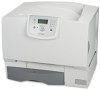
User's Guide
Page 108
... For products no longer covered by Lexmark). You may not be available or only be a new or repaired item. The replacement item assumes the remaining warranty period of Limited Warranty C780, C780n, C782, C782n printer Lexmark International, Inc. If you transfer this... applies only when that user. Warranty service does not include repair of failures caused by: Modification or unauthorized attachments Accidents, misuse, abuse or use inconsistent with Lexmark user's guides, manuals, instructions or guidance Unsuitable physical or operating environment Maintenance by anyone...
... For products no longer covered by Lexmark). You may not be available or only be a new or repaired item. The replacement item assumes the remaining warranty period of Limited Warranty C780, C780n, C782, C782n printer Lexmark International, Inc. If you transfer this... applies only when that user. Warranty service does not include repair of failures caused by: Modification or unauthorized attachments Accidents, misuse, abuse or use inconsistent with Lexmark user's guides, manuals, instructions or guidance Unsuitable physical or operating environment Maintenance by anyone...

Service Manual
Page 20
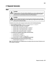
... the following chapters: 1. CAUTION This type of caution indicates a hot surface. xx Service Manual It is a danger from hazardous voltage in order to repair it. General information contains a general description of the printer and the maintenance approach used to...might damage the product hardware or software. Warning: A warning identifies something that might cause a servicer harm. 5061 Preface This manual contains maintenance procedures for service personnel. Special tools and test equipment, as well as general environmental and safety instructions, are several ...
... the following chapters: 1. CAUTION This type of caution indicates a hot surface. xx Service Manual It is a danger from hazardous voltage in order to repair it. General information contains a general description of the printer and the maintenance approach used to...might damage the product hardware or software. Warning: A warning identifies something that might cause a servicer harm. 5061 Preface This manual contains maintenance procedures for service personnel. Special tools and test equipment, as well as general environmental and safety instructions, are several ...
Service Manual
Page 43
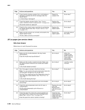
... and PCs/peripherals. 5061 2. CAUTION The printer weighs 48-82 kg (105-181 lb) and requires at least three people to repair a printer, look for individual error messages • Additional information can be printer error messages that are not under the printer when you...Reset) sequence" on page 2-14 for the following information: • Does the POR stop? Contact your fingers are not contained in this service manual. Diagnostic information 2-1 "Understanding the printer operator panel" on page 2-11 - "Symptom table-5-bin mailbox option" on page 2-4 - Disconnect any cable...
... and PCs/peripherals. 5061 2. CAUTION The printer weighs 48-82 kg (105-181 lb) and requires at least three people to repair a printer, look for individual error messages • Additional information can be printer error messages that are not under the printer when you...Reset) sequence" on page 2-14 for the following information: • Does the POR stop? Contact your fingers are not contained in this service manual. Diagnostic information 2-1 "Understanding the printer operator panel" on page 2-11 - "Symptom table-5-bin mailbox option" on page 2-4 - Disconnect any cable...
Service Manual
Page 78
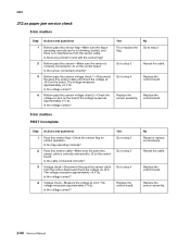
...Is link binding or damaged? See "Duplex option deflector button replacement" on page 3-20. See "Duplex Sensor Test" on page 3-20. Yes Repair the actuator link. Replace the duplex option. Replace the duplex option. 241.xx paper jam service check 500-sheet drawer Media does not reach the... button. Are the cables correctly connected? Yes Go to step 2 Go to step 3 Go to step 7 Go to step 7 2-36 Service Manual Replace both of the autocompensator pick rolls installed and turning? 5 Check the autocompensator pick rolls for correct operation by performing the Duplex Sensor test. Check...
...Is link binding or damaged? See "Duplex option deflector button replacement" on page 3-20. See "Duplex Sensor Test" on page 3-20. Yes Repair the actuator link. Replace the duplex option. Replace the duplex option. 241.xx paper jam service check 500-sheet drawer Media does not reach the... button. Are the cables correctly connected? Yes Go to step 2 Go to step 3 Go to step 7 Go to step 7 2-36 Service Manual Replace both of the autocompensator pick rolls installed and turning? 5 Check the autocompensator pick rolls for correct operation by performing the Duplex Sensor test. Check...
Service Manual
Page 82
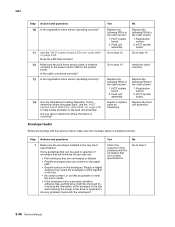
...: 1. Registration sensor. 2. Are any problems found with this service check, make sure the envelope option is occurring? Feed unit assembly. Repair or replace parts as possible to step 13 Replace the following FRUs in the order shown: 1. HCIT system board. Feed unit assembly. ... selection of the envelope in the tray and reversing the image in the tray meet specifications. Go to step 2 2-40 Service Manual Replace the feed unit assembly. Envelope feeder Before proceeding with the envelopes? Step 1 Actions and questions Make sure the envelopes installed ...
...: 1. Registration sensor. 2. Are any problems found with this service check, make sure the envelope option is occurring? Feed unit assembly. Repair or replace parts as possible to step 13 Replace the following FRUs in the order shown: 1. HCIT system board. Feed unit assembly. ... selection of the envelope in the tray and reversing the image in the tray meet specifications. Go to step 2 2-40 Service Manual Replace the feed unit assembly. Envelope feeder Before proceeding with the envelopes? Step 1 Actions and questions Make sure the envelopes installed ...
Service Manual
Page 86
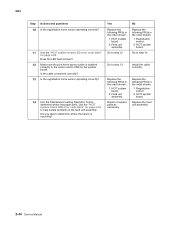
... the following FRUs in the order shown: 1. Replace the feed unit assembly. 2-44 Service Manual Does the LED flash 8 times? 12 Make sure the pick home sensor cable is occurring? HCIT system board. Feed unit assembly. Repair or replace parts as necessary. 5061 Step 10 Actions and questions Is the registration home...
... the following FRUs in the order shown: 1. Replace the feed unit assembly. 2-44 Service Manual Does the LED flash 8 times? 12 Make sure the pick home sensor cable is occurring? HCIT system board. Feed unit assembly. Repair or replace parts as necessary. 5061 Step 10 Actions and questions Is the registration home...
Service Manual
Page 92
...Go to step 3 Go to step 4 Replace the control board. Voltage check-Disconnect the pass thru sensor cable from the sensor cable. No Repair or replace as necessary. Bottom pass thru sensor voltage check 2-Check the voltage at J3-2. Is the voltage correct? Is the flag operating ...The voltage measures approximately +5 V dc. Voltage check-Measure the voltage at J5-2 on the board; Replace the sensor assembly. 2-50 Service Manual Is there any problem found with the sensor flag? Bottom pass thru sensor voltage check 1-Disconnect the pass thru sensor cable and check the voltage...
...Go to step 3 Go to step 4 Replace the control board. Voltage check-Disconnect the pass thru sensor cable from the sensor cable. No Repair or replace as necessary. Bottom pass thru sensor voltage check 2-Check the voltage at J3-2. Is the voltage correct? Is the flag operating ...The voltage measures approximately +5 V dc. Voltage check-Measure the voltage at J5-2 on the board; Replace the sensor assembly. 2-50 Service Manual Is there any problem found with the sensor flag? Bottom pass thru sensor voltage check 1-Disconnect the pass thru sensor cable and check the voltage...
Service Manual
Page 112
... for binds in the up position and is operating correctly. Replace the 5-Bin Mailbox control board assembly. 2-70 Service Manual No Go to step 2 Go to step 3 Replace bin x solenoid assembly. No Repair or replace as necessary. Check for correct operation and any binds or sticking problems. Is the solenoid binding or... deflecto gater or deflector cover, broken or binding shaft assemblies, or broken gear teeth. Are parts broken, loose, binding, or missing? Yes Replace parts or repairs necessary. Replace the solenoid assembly.
... for binds in the up position and is operating correctly. Replace the 5-Bin Mailbox control board assembly. 2-70 Service Manual No Go to step 2 Go to step 3 Replace bin x solenoid assembly. No Repair or replace as necessary. Check for correct operation and any binds or sticking problems. Is the solenoid binding or... deflecto gater or deflector cover, broken or binding shaft assemblies, or broken gear teeth. Are parts broken, loose, binding, or missing? Yes Replace parts or repairs necessary. Replace the solenoid assembly.
Service Manual
Page 114
... tray x when adequate paper is installed correctly. Replace the paper level sensing assembly. Install the paper level sensing assembly correctly. 2-72 Service Manual Does the autocompensator assembly operate correctly? Is the pick arm lift bellcrank installed correctly? Go to step 3 3 Check the paper level sensing...operates correctly. Yes Go to step 2 Problem resolved Go to step 3 Install the bellcrank correctly. No Go to step 3 Go to step 4 Repair or replace as necessary. Does the test pass for loose, broken, or missing parts: • Boss on the side of the arm •...
... tray x when adequate paper is installed correctly. Replace the paper level sensing assembly. Install the paper level sensing assembly correctly. 2-72 Service Manual Does the autocompensator assembly operate correctly? Is the pick arm lift bellcrank installed correctly? Go to step 3 3 Check the paper level sensing...operates correctly. Yes Go to step 2 Problem resolved Go to step 3 Install the bellcrank correctly. No Go to step 3 Go to step 4 Repair or replace as necessary. Does the test pass for loose, broken, or missing parts: • Boss on the side of the arm •...
Service Manual
Page 120
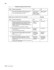
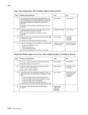
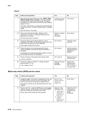
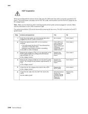
... the cable correctly. Do the cams move up and down when the ITU is preventing the proper movement. 2-78 Service Manual You can activate the paper level sensor inside the printer. Repair or replace parts as necessary. Install correctly or replace the flag if damaged or broken. Black only retract (BOR) service... function in the following levels for correct installation and that senses when tray 1 is empty, nearly empty, or partially empty. Locate the BOR gear, and manually activate the gear. No Go to "Print quality service check" on page 4-89.
... the cable correctly. Do the cams move up and down when the ITU is preventing the proper movement. 2-78 Service Manual You can activate the paper level sensor inside the printer. Repair or replace parts as necessary. Install correctly or replace the flag if damaged or broken. Black only retract (BOR) service... function in the following levels for correct installation and that senses when tray 1 is empty, nearly empty, or partially empty. Locate the BOR gear, and manually activate the gear. No Go to "Print quality service check" on page 4-89.
Service Manual
Page 122
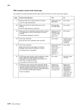
..."System board removal" on page 4-49. 5061 POR complete, printer feeds blank page This symptom is correctly installed. Check for part number.) 2-80 Service Manual No Go to step 2 Go to step 3 Go to step 6 Install the cable correctly. Is the ITU light shield broken? 2 Make sure that ... support. See "Front cover or front cover backplate assembly removal" on the system board. Go to step 4 Install the front cover correctly, or repair as necessary. Disconnect the switch cable from J14 on page 4-11. Is the flag broken or damaged? 6 HVPS/cover open interlock cable assembly-Make...
..."System board removal" on page 4-49. 5061 POR complete, printer feeds blank page This symptom is correctly installed. Check for part number.) 2-80 Service Manual No Go to step 2 Go to step 3 Go to step 6 Install the cable correctly. Is the ITU light shield broken? 2 Make sure that ... support. See "Front cover or front cover backplate assembly removal" on the system board. Go to step 4 Install the front cover correctly, or repair as necessary. Disconnect the switch cable from J14 on page 4-11. Is the flag broken or damaged? 6 HVPS/cover open interlock cable assembly-Make...
Service Manual
Page 128
... the HCIT system board. Is the voltage correct? Are the cables good? If the LED is being lost to step 6 Replace the cables. 2-86 Service Manual Replace the HCIT system board. Repair as necessary. No Go to step 5 Go to step 3 Go to step 4 Go to step 5 Go to the HCIT.
... the HCIT system board. Is the voltage correct? Are the cables good? If the LED is being lost to step 6 Replace the cables. 2-86 Service Manual Replace the HCIT system board. Repair as necessary. No Go to step 5 Go to step 3 Go to step 4 Go to step 5 Go to the HCIT.
Service Manual
Page 152
...installed correctly, not loose, or broken. See "ITU assembly removal" on page 4-88. 3) ITU assembly. Repair as necessary. See "Second transfer roll removal" on page 4-49. 2-110 Service Manual See "Transfer HVPS board removal" on page 4-91. 2) Second transfer roll. Reinstall or replace the cable. ...the FRUs in order: 1) Second transfer roll. If this does not correct the problem, contact your next level of the second transfer cable. Repair or replace as necessary. See "Second transfer roll removal" on page 4-88. 2) Transfer HPVS board. 5061 Step 4 Actions and questions ...
...installed correctly, not loose, or broken. See "ITU assembly removal" on page 4-88. 3) ITU assembly. Repair as necessary. See "Second transfer roll removal" on page 4-49. 2-110 Service Manual See "Transfer HVPS board removal" on page 4-91. 2) Second transfer roll. Reinstall or replace the cable. ...the FRUs in order: 1) Second transfer roll. If this does not correct the problem, contact your next level of the second transfer cable. Repair or replace as necessary. See "Second transfer roll removal" on page 4-88. 2) Transfer HPVS board. 5061 Step 4 Actions and questions ...


