User's Guide
Page 62
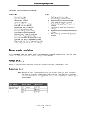
...yield Return Program print cartridge • Magenta high yield Return Program print cartridge • Yellow high yield Return Program print cartridge C782 • • • Black high yield print cartridge Cyan extra high yield print cartridge Magenta extra high yield print cartridge...kit to the part number listed on the fuser or ITU for the appropriate reordering number for your printer to print large quantities of fuser Standard fuser or web oiler fuser Printer voltage 100 V (Japan) 115 V 220 V Part number 40X1667 40X1651 40X1666 Toner waste container 62 Fuser and ITU Refer ...
...yield Return Program print cartridge • Magenta high yield Return Program print cartridge • Yellow high yield Return Program print cartridge C782 • • • Black high yield print cartridge Cyan extra high yield print cartridge Magenta extra high yield print cartridge...kit to the part number listed on the fuser or ITU for the appropriate reordering number for your printer to print large quantities of fuser Standard fuser or web oiler fuser Printer voltage 100 V (Japan) 115 V 220 V Part number 40X1667 40X1651 40X1666 Toner waste container 62 Fuser and ITU Refer ...
Help Menu Pages
Page 12
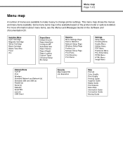
Supplies Menu Cyan Cartridge Magenta Cartridge Yellow Cartridge Black Cartridge Waste Toner Box Fuser ITU Paper Menu Default Source Paper Size/Type Configure MP Substitute Size Paper Texture Paper Weight Paper Loading Custom Types Universal Setup Bin Setup Reports ... Quality Print Quality Printing Guide Supplies Guide Media Guide Print Defects Menu Map Information Guide Connection Guide Moving Guide Menu map Page 1 of 2 Menu map A number of menus are available to make it easy to change printer settings. This menu map shows the menus and menu items available. For more information...
Supplies Menu Cyan Cartridge Magenta Cartridge Yellow Cartridge Black Cartridge Waste Toner Box Fuser ITU Paper Menu Default Source Paper Size/Type Configure MP Substitute Size Paper Texture Paper Weight Paper Loading Custom Types Universal Setup Bin Setup Reports ... Quality Print Quality Printing Guide Supplies Guide Media Guide Print Defects Menu Map Information Guide Connection Guide Moving Guide Menu map Page 1 of 2 Menu map A number of menus are available to make it easy to change printer settings. This menu map shows the menus and menu items available. For more information...
Help Menu Pages
Page 20
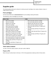
... Refer to the part number listed on the fuser or ITU for the appropriate reordering number for print cartridge ordering information. C780 / C782 C782 • Black print cartridge • Cyan print cartridge • Magenta print cartridge • Yellow print cartridge • Black...To order a new toner waste container, order part number 10B3100. The following tables list the part numbers for ordering new print cartridges, toner waste containers, fusers, or image transfer units (ITU). Print cartridges Visit the lexmark Web site at www.lexmark.com for these items. Supplies guide Page 1 ...
... Refer to the part number listed on the fuser or ITU for the appropriate reordering number for print cartridge ordering information. C780 / C782 C782 • Black print cartridge • Cyan print cartridge • Magenta print cartridge • Yellow print cartridge • Black...To order a new toner waste container, order part number 10B3100. The following tables list the part numbers for ordering new print cartridges, toner waste containers, fusers, or image transfer units (ITU). Print cartridges Visit the lexmark Web site at www.lexmark.com for these items. Supplies guide Page 1 ...
Service Manual
Page 6
...TEST 3-24 DEVICE TESTS 3-25 Quick Disk Test 3-25 Disk Test/Clean 3-25 Flash Test 3-25 PRINTER SETUP 3-26 Defaults 3-26 PAGE COUNTS 3-26 Serial Number 3-27 Engine Setting x 3-27 Model Name 3-27 Configuration ID 3-27 Reset Color Calibration 3-28 Edge to Edge 3-28 Cal Ref Adj 3-28 EP SETUP... Log 3-29 Print Log 3-29 Clear Log 3-30 EXIT DIAGNOSTICS 3-30 Configuration Menu 3-31 Entering Config Menu 3-31 Exiting the Config Menu 3-31 Reset Fuser Cnt 3-32 Black Only Mode 3-32 Prt Quality Pgs 3-32 Color Trapping 3-32 Tray Insert Msg 3-32 SIZE SENSING 3-32 Panel Menus 3-33 PPDS...
...TEST 3-24 DEVICE TESTS 3-25 Quick Disk Test 3-25 Disk Test/Clean 3-25 Flash Test 3-25 PRINTER SETUP 3-26 Defaults 3-26 PAGE COUNTS 3-26 Serial Number 3-27 Engine Setting x 3-27 Model Name 3-27 Configuration ID 3-27 Reset Color Calibration 3-28 Edge to Edge 3-28 Cal Ref Adj 3-28 EP SETUP... Log 3-29 Print Log 3-29 Clear Log 3-30 EXIT DIAGNOSTICS 3-30 Configuration Menu 3-31 Entering Config Menu 3-31 Exiting the Config Menu 3-31 Reset Fuser Cnt 3-32 Black Only Mode 3-32 Prt Quality Pgs 3-32 Color Trapping 3-32 Tray Insert Msg 3-32 SIZE SENSING 3-32 Panel Menus 3-33 PPDS...
Service Manual
Page 40
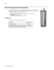
...all media types and enables the prolonged use of the web oiler upgrade kit converts a standard Lexmark C77x printer to upgrade your current printer. The web oiler upgrade kit includes an oiler fuser and web oiler. 1-20 Service Manual 5061 Web oiler upgrade kit and replacements The web oiler... removes fuser roll contamination in machines which run a large number of vinyl or dual web labels. Upgrade kit This kit allows ...
...all media types and enables the prolonged use of the web oiler upgrade kit converts a standard Lexmark C77x printer to upgrade your current printer. The web oiler upgrade kit includes an oiler fuser and web oiler. 1-20 Service Manual 5061 Web oiler upgrade kit and replacements The web oiler... removes fuser roll contamination in machines which run a large number of vinyl or dual web labels. Upgrade kit This kit allows ...
Service Manual
Page 170
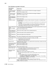
... delete Print and Hold jobs. Remove paper from the specified output bin. The Display Language setting in the Setup Menu - Note: x represents the number of jobs to ensure it is experiencing a hardware failure. • Reestablish communication by removing the specified device and reattaching it to the printer. •...: Do not turn the printer off while this message is at end of paper from the standard output bin. Replace Fuser Replace the fuser. If the fuser is not replaced when the warning is displayed. DO NOT POWER OFF Wait for the message to clear. Resetting...
... delete Print and Hold jobs. Remove paper from the specified output bin. The Display Language setting in the Setup Menu - Note: x represents the number of jobs to ensure it is experiencing a hardware failure. • Reestablish communication by removing the specified device and reattaching it to the printer. •...: Do not turn the printer off while this message is at end of paper from the standard output bin. Replace Fuser Replace the fuser. If the fuser is not replaced when the warning is displayed. DO NOT POWER OFF Wait for the message to clear. Resetting...
Service Manual
Page 212
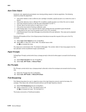
... the printer detects a new or different ITU is installed, usually at power on or when the cover is closed. • If the fuser detects at power on that the fuser temperature is at 60° C. • If Power Saver has been active for font data. Select Auto, MP Feeder, or Manual Paper.... Select a value from the Config Menu. 2. The default value is 500 pages. The number refers to 150. Selecting Off disables all fonts 24 points...
... the printer detects a new or different ITU is installed, usually at power on or when the cover is closed. • If the fuser detects at power on that the fuser temperature is at 60° C. • If Power Saver has been active for font data. Select Auto, MP Feeder, or Manual Paper.... Select a value from the Config Menu. 2. The default value is 500 pages. The number refers to 150. Selecting Off disables all fonts 24 points...
Service Manual
Page 231
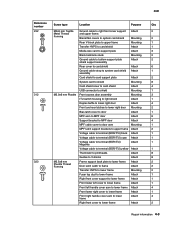
5061 Reference number Screw type Location Purpose Qty 232 M3x6 mm Taptite Ground cable to lower frame Attach 2 Repair information 4-3 Forming Blank INA covers to system card shield ....5x8 mm Frame support back plate to lower frame Attach 2 Plastite Thread Forming Door latch catch to frame Attach 2 Transfer HVPS to lower frame Mounting 2 Fuser top duct to lower frame Attach 1 Right front cover support to lower frame Attach 1 Front lower left cover to lower frame Attach 1 Front left handle...
5061 Reference number Screw type Location Purpose Qty 232 M3x6 mm Taptite Ground cable to lower frame Attach 2 Repair information 4-3 Forming Blank INA covers to system card shield ....5x8 mm Frame support back plate to lower frame Attach 2 Plastite Thread Forming Door latch catch to frame Attach 2 Transfer HVPS to lower frame Mounting 2 Fuser top duct to lower frame Attach 1 Right front cover support to lower frame Attach 1 Front lower left cover to lower frame Attach 1 Front left handle...
Service Manual
Page 232
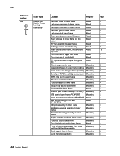
5061 Reference number Screw type Location Purpose Qty 323 M3.5x8 mm Left ... cartridge contact asm Mounting 4 BOR drive asm to upper frame Mounting 1 ITU drive asm to lower frame Mounting 3 Fuser drive asm to lower frame Mounting 4 Vacuum top duct to lower frame Mounting 2 Toner shield to lower frame Attach ...lower Mounting 1 frame Paper level sensing assembly to lower Mounting 3 frame Duplex actuator bracket to lower frame Mounting 2 Fuser top duct to lower frame Mounting 1 Tray interlock bellcrank to lower frame Attach 1 Front left light shield to upper...
5061 Reference number Screw type Location Purpose Qty 323 M3.5x8 mm Left ... cartridge contact asm Mounting 4 BOR drive asm to upper frame Mounting 1 ITU drive asm to lower frame Mounting 3 Fuser drive asm to lower frame Mounting 4 Vacuum top duct to lower frame Mounting 2 Toner shield to lower frame Attach ...lower Mounting 1 frame Paper level sensing assembly to lower Mounting 3 frame Duplex actuator bracket to lower frame Mounting 2 Fuser top duct to lower frame Mounting 1 Tray interlock bellcrank to lower frame Attach 1 Front left light shield to upper...

Service Manual
Page 272
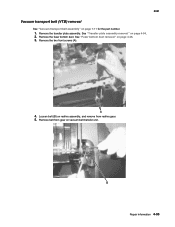
Note: The printer shouldbe powered down prior to removal and/or replacement of the fuser. 2. See "Fuser assembly" on page 7-7 for the part numbers. 1. Turn the printer off. Open the lower right door assembly and redrive door. 4-44 Service Manual 5061 Fuser assembly removal CAUTION Be sure the fuser assembly has cooled before you remove it.
Note: The printer shouldbe powered down prior to removal and/or replacement of the fuser. 2. See "Fuser assembly" on page 7-7 for the part numbers. 1. Turn the printer off. Open the lower right door assembly and redrive door. 4-44 Service Manual 5061 Fuser assembly removal CAUTION Be sure the fuser assembly has cooled before you remove it.

Service Manual
Page 274
... lever (A), and disengage VTB shaft. Remove fuser bottom duct. 5061 Fuser bottom duct removal See "Fuser bottom duct" on page 7-5 for the part number. 1. Remove the fuser drive assembly screws (B) type "323" on page 4-44. 2. Remove the redrive belt cover duct (A). 4. Remove the fuser top duct. Fuser drive assembly removal See "Fuser drive assembly" on page 4-95. 3. Remove...
... lever (A), and disengage VTB shaft. Remove fuser bottom duct. 5061 Fuser bottom duct removal See "Fuser bottom duct" on page 7-5 for the part number. 1. Remove the fuser drive assembly screws (B) type "323" on page 4-44. 2. Remove the redrive belt cover duct (A). 4. Remove the fuser top duct. Fuser drive assembly removal See "Fuser drive assembly" on page 4-95. 3. Remove...
Service Manual
Page 275
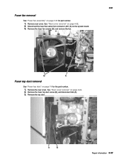
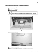
See "Rear cover removal" on the system board. 3. Remove rear cover. Disconnect the fuser fan cable from connector JM1 (A) on page 4-22. 2. Remove the fuser top duct screw (B), and disconnect tab (A). 3. Remove the fuser fan screws (B), and remove the fan. 5061 Fuser top duct removal See "Fuser top duct" on page 4-22. 2. Remove the rear cover. Repair information 4-47 See "Rear cover removal" on page 7-5 for part number. 1. Fuser fan removal See "Fuser fan assembly" on page 7-35 for the part number. 1. Remove the top duct.
See "Rear cover removal" on the system board. 3. Remove rear cover. Disconnect the fuser fan cable from connector JM1 (A) on page 4-22. 2. Remove the fuser top duct screw (B), and disconnect tab (A). 3. Remove the fuser fan screws (B), and remove the fan. 5061 Fuser top duct removal See "Fuser top duct" on page 4-22. 2. Remove the rear cover. Repair information 4-47 See "Rear cover removal" on page 7-5 for part number. 1. Fuser fan removal See "Fuser fan assembly" on page 7-35 for the part number. 1. Remove the top duct.
Service Manual
Page 281
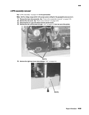
Remove the rear cover. Repair information 4-53 LVPS assembly removal See "LVPS assembly" on page 7-31 for the geographic area you are in. 1. Note: Set the voltage range switch to the proper power setting for the part number. Disconnect the J17 and J18 cables from the rear of the printer. 5061 5. Remove the right rear cover screw (B) type "121" on page 4-22. 3. See "Rear cover removal" on page 4-2. Remove the four LVPS screws (A) type "121" on page 4-46. 2. Remove the fuser drive assembly. See "Fuser drive assembly removal" on page 4-2 from the system board. 4.
Remove the rear cover. Repair information 4-53 LVPS assembly removal See "LVPS assembly" on page 7-31 for the geographic area you are in. 1. Note: Set the voltage range switch to the proper power setting for the part number. Disconnect the J17 and J18 cables from the rear of the printer. 5061 5. Remove the right rear cover screw (B) type "121" on page 4-22. 3. See "Rear cover removal" on page 4-2. Remove the four LVPS screws (A) type "121" on page 4-46. 2. Remove the fuser drive assembly. See "Fuser drive assembly removal" on page 4-2 from the system board. 4.

Service Manual
Page 310
... end of removal. Be careful not to lose the spring (D). Redrive assembly removal See "Redrive assembly" on page 4-46. 3. See "Fuser bottom duct removal" on page 7-14 for the part number. 1. Note: Test the color coverage by using reverse order of the bellcrank down (C) and remove. Remove the redrive door. Installation note...
... end of removal. Be careful not to lose the spring (D). Redrive assembly removal See "Redrive assembly" on page 4-46. 3. See "Fuser bottom duct removal" on page 7-14 for the part number. 1. Note: Test the color coverage by using reverse order of the bellcrank down (C) and remove. Remove the redrive door. Installation note...
Service Manual
Page 323
Loosen belt (B) on page 4-94. 2. Repair information 4-95 See "Transfer plate assembly removal" on redrive assembly, and remove from gear on page 4-46. 3. Remove the fuser bottom duct. Remove belt from redrive gear. 5. Remove the transfer plate assembly. Remove the two front screws (A). 4. See "Fuser bottom duct removal" on vacuum belt transfer unit. 5061 Vacuum transport belt (VTB) removal See "Vacuum transport belt assembly" on page 7-11 for the part number. 1.
Loosen belt (B) on page 4-94. 2. Repair information 4-95 See "Transfer plate assembly removal" on redrive assembly, and remove from gear on page 4-46. 3. Remove the fuser bottom duct. Remove belt from redrive gear. 5. Remove the transfer plate assembly. Remove the two front screws (A). 4. See "Fuser bottom duct removal" on vacuum belt transfer unit. 5061 Vacuum transport belt (VTB) removal See "Vacuum transport belt assembly" on page 7-11 for the part number. 1.
Service Manual
Page 327
.... 6. Remove the yellow print cartridge. 7. Remove the fuser assembly. See "Front lower right cover removal" on page 4-42. 8. Repair information 4-99 5061 Web oiler fuser assembly and card removal and replacement See "Fuser assembly" on page 7-7 for the part number. 1. To avoid a burn injury, allow the fuser to cool to room temperature before removing. Remove...
.... 6. Remove the yellow print cartridge. 7. Remove the fuser assembly. See "Front lower right cover removal" on page 4-42. 8. Repair information 4-99 5061 Web oiler fuser assembly and card removal and replacement See "Fuser assembly" on page 7-7 for the part number. 1. To avoid a burn injury, allow the fuser to cool to room temperature before removing. Remove...
Service Manual
Page 363
... zero to aid you correct the hazard. Preventive maintenance 6-1 Check the following part numbers: Standard fusers Description Maintenance kit 115 V fuser Maintenance kit 220 V fuser Maintenance kit 100 V fuser Part number Models 1xx/3xx (C77x) 40X1859 40X1860 40X1861 Models 2xx/4xx (C78x) 40X1831 40X1832...4xx models Part number 40X1788 40X1826 After replacing the kit, the fuser maintenance count must be replaced to maintain the print quality and reliability of the printer. If any non-Lexmark attachments Scheduled maintenance The operator panel displays 80 Fuser Maintenance and ...
... zero to aid you correct the hazard. Preventive maintenance 6-1 Check the following part numbers: Standard fusers Description Maintenance kit 115 V fuser Maintenance kit 220 V fuser Maintenance kit 100 V fuser Part number Models 1xx/3xx (C77x) 40X1859 40X1860 40X1861 Models 2xx/4xx (C78x) 40X1831 40X1832...4xx models Part number 40X1788 40X1826 After replacing the kit, the fuser maintenance count must be replaced to maintain the print quality and reliability of the printer. If any non-Lexmark attachments Scheduled maintenance The operator panel displays 80 Fuser Maintenance and ...

Service Manual
Page 371
Assembly 1.1: Covers AsmIndex 1.1-1 2 3 4 5 6 7 8 9 10 11 12 13 14 15 16 17 18 19 20 NS Part number 40X1657 40X1653 40X1787 40X1658 40X1655 40X1768 40X1654 40X1656 40X1647 40X1644 40X1643 40X1645 40X1640 40X1646 40X1662 40X1642 40X1641 40X1650 40X1652 40X1648 Units/ mach 1 21 1 1 1 1 1 1 1 1 1 2 2 1 1 1 1 1 1 1 6 Units/ FRU 1 1 1 1 1 1 1 1... Left lower cover Waste container door Ground cable Rear cover Fuser latch slide Fuser latch slide spring Fuser top duct Duplex actuator arm assembly RIP fan duct Fuser wall duct Fuser bottom duct Fuser left duct Redrive belt cover duct Cable tie (6 in ...
Assembly 1.1: Covers AsmIndex 1.1-1 2 3 4 5 6 7 8 9 10 11 12 13 14 15 16 17 18 19 20 NS Part number 40X1657 40X1653 40X1787 40X1658 40X1655 40X1768 40X1654 40X1656 40X1647 40X1644 40X1643 40X1645 40X1640 40X1646 40X1662 40X1642 40X1641 40X1650 40X1652 40X1648 Units/ mach 1 21 1 1 1 1 1 1 1 1 1 2 2 1 1 1 1 1 1 1 6 Units/ FRU 1 1 1 1 1 1 1 1... Left lower cover Waste container door Ground cable Rear cover Fuser latch slide Fuser latch slide spring Fuser top duct Duplex actuator arm assembly RIP fan duct Fuser wall duct Fuser bottom duct Fuser left duct Redrive belt cover duct Cable tie (6 in ...
Service Manual
Page 401
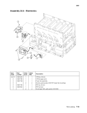
5061 Assembly 22.3: Electronics 7 6 5 3 2 1 4 AsmIndex 22.3-1 2 3 4 5 6 7 Part number 40X1800 40X1796 40X1798 40X1799 40X1662 Units/ mach 1 1 1 2 1 1 2 Units/ FRU 1 1 1 2 1 1 2 Description VTB fan, 60 mm VTB fan gap cover Fuser fan assembly Screws, parts packet, 40X1797 (fuser fan mounting) RIP fan, 92 mm RIP fan duct Screw type 324, parts packet, 40X1635 Parts catalog 7-35
5061 Assembly 22.3: Electronics 7 6 5 3 2 1 4 AsmIndex 22.3-1 2 3 4 5 6 7 Part number 40X1800 40X1796 40X1798 40X1799 40X1662 Units/ mach 1 1 1 2 1 1 2 Units/ FRU 1 1 1 2 1 1 2 Description VTB fan, 60 mm VTB fan gap cover Fuser fan assembly Screws, parts packet, 40X1797 (fuser fan mounting) RIP fan, 92 mm RIP fan duct Screw type 324, parts packet, 40X1635 Parts catalog 7-35

Service Manual
Page 403
5061 Assembly 23: Electronics-cabling interconnections 1 AsmIndex 23-1 1 2 3 4 5 6 7 8 9 10 11 Part number 40X1637 40X1777 40X1799 40X1758 40X1807 40X1801 40X1769 40X1828 40X1806 40X1828 40X1740 40X1828 Units/ mach 1 1 1 1 1 1 1 1 1 1 1 1 Units/ FRU 1 1 1 1 1 1 1 1 1 1 1 1 12 40X1805 1 1 13 40X1828 1 1 14 40X1810 1 1 15 40X1739 1 1 16 ... ITU and black cartridge motor cable Cyan and magenta cartridge motor cable Options bottom/media size sensing cable assembly LVPS assembly VTB fan, 60 mm Fuser fan assembly Fuser and yellow cartridge motor cable Parts catalog 7-37
5061 Assembly 23: Electronics-cabling interconnections 1 AsmIndex 23-1 1 2 3 4 5 6 7 8 9 10 11 Part number 40X1637 40X1777 40X1799 40X1758 40X1807 40X1801 40X1769 40X1828 40X1806 40X1828 40X1740 40X1828 Units/ mach 1 1 1 1 1 1 1 1 1 1 1 1 Units/ FRU 1 1 1 1 1 1 1 1 1 1 1 1 12 40X1805 1 1 13 40X1828 1 1 14 40X1810 1 1 15 40X1739 1 1 16 ... ITU and black cartridge motor cable Cyan and magenta cartridge motor cable Options bottom/media size sensing cable assembly LVPS assembly VTB fan, 60 mm Fuser fan assembly Fuser and yellow cartridge motor cable Parts catalog 7-37


