Service Manual
Page 15
... Programmable Read-Only Memory Electrostatic Discharge Field Replaceable Unit Gigabyte High Voltage Power Supply Black Light Amplification by Stimulated Emission of Radiation Liquid Crystal Display Light-Emitting Diode Low Voltage Power Supply Magenta Multipurpose Feeder Microswitch Nonvolatile Random Access Memory Optical Sensor Photoconductor Picture element Power-On Reset Power-On Self Test Pulse Width Modulation Raster Imaging Processor Synchronous...
... Programmable Read-Only Memory Electrostatic Discharge Field Replaceable Unit Gigabyte High Voltage Power Supply Black Light Amplification by Stimulated Emission of Radiation Liquid Crystal Display Light-Emitting Diode Low Voltage Power Supply Magenta Multipurpose Feeder Microswitch Nonvolatile Random Access Memory Optical Sensor Photoconductor Picture element Power-On Reset Power-On Self Test Pulse Width Modulation Raster Imaging Processor Synchronous...
Service Manual
Page 43
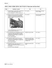
... rear cover. Press the camshaft follower into the proper location. A Is the camshaft follower on the right side. See "Low voltage power supply (LVPS) removal" on the back of the low voltage power supply (LVPS). No Set the switch for any other damage. Go to be pressed down into the groove. Replace the fuser cable...JLVPS1 for any other damage. Yes Go to the system card, the cable for pinch points, and the cable or connector for proper country voltage. 5022-xxx 120.01, 120.02, 120.08-120.10, 120.13-120.15-Fuser error service check Step Questions / actions 1 Check...
... rear cover. Press the camshaft follower into the proper location. A Is the camshaft follower on the right side. See "Low voltage power supply (LVPS) removal" on the back of the low voltage power supply (LVPS). No Set the switch for any other damage. Go to be pressed down into the groove. Replace the fuser cable...JLVPS1 for any other damage. Yes Go to the system card, the cable for pinch points, and the cable or connector for proper country voltage. 5022-xxx 120.01, 120.02, 120.08-120.10, 120.13-120.15-Fuser error service check Step Questions / actions 1 Check...

Service Manual
Page 45
Is the cable damaged? See "Low voltage power supply (LVPS) removal" on the back of the low voltage power supply (LVPS). Is the cable damaged? 3 Remove the fuser. Replace the fuser cable. Is the cable damaged? Go to step 2. See "System card ...xxx 120.03-Fuser error service check Step Questions / actions Yes 1 Check the input voltage switch on page 4-60. Check the connector JFUSER1 for any other damage. See "Fuser removal" on the back of the low voltage power supply (LVPS). No Set the switch for any other damage. Are the connectors damaged? ...
Is the cable damaged? See "Low voltage power supply (LVPS) removal" on the back of the low voltage power supply (LVPS). Is the cable damaged? 3 Remove the fuser. Replace the fuser cable. Is the cable damaged? Go to step 2. See "System card ...xxx 120.03-Fuser error service check Step Questions / actions Yes 1 Check the input voltage switch on page 4-60. Check the connector JFUSER1 for any other damage. See "Fuser removal" on the back of the low voltage power supply (LVPS). No Set the switch for any other damage. Are the connectors damaged? ...
Service Manual
Page 66
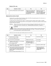
...where you see this measure approximately +5 V dc? Step Questions / actions 1 Check the AC line voltage. Go to step 4. See "Low voltage power supply (LVPS) removal" on , and measure the voltage between JLVPS1 pin 1 and ground. No Replace the system card with a new, and not previously installed...If the base printer operates correctly, replace the 500-sheet option assembly. Does this symbol, there is a danger from hazardous voltage in order to step 5. Disconnect the JLVPS1 cable from the printer. Warning: Observe all necessary ESD precautions when removing and ...
...where you see this measure approximately +5 V dc? Step Questions / actions 1 Check the AC line voltage. Go to step 4. See "Low voltage power supply (LVPS) removal" on , and measure the voltage between JLVPS1 pin 1 and ground. No Replace the system card with a new, and not previously installed...If the base printer operates correctly, replace the 500-sheet option assembly. Does this symbol, there is a danger from hazardous voltage in order to step 5. Disconnect the JLVPS1 cable from the printer. Warning: Observe all necessary ESD precautions when removing and ...

Service Manual
Page 73
... / actions 1 Is the fuser properly installed? 2 Replace the fuser. No Install the fuser properly. Reset the specific photoconductor unit. Problem solved. Yes Problem solved. see "Low voltage power supply (LVPS) removal" on page 4-60. Check the EP drive assembly and transfer belt assembly for correct operation. Replace as necessary. Print quality-horizontal banding Step...
... / actions 1 Is the fuser properly installed? 2 Replace the fuser. No Install the fuser properly. Reset the specific photoconductor unit. Problem solved. Yes Problem solved. see "Low voltage power supply (LVPS) removal" on page 4-60. Check the EP drive assembly and transfer belt assembly for correct operation. Replace as necessary. Print quality-horizontal banding Step...

Service Manual
Page 134
... fibers, carpets, and furniture. • Put the ESD wrist strap on a table. • If possible, keep all the usual precautions, such as the high-voltage power supply. • After part replacement, ensure the wiring harness is not caught or damaged. • Do not attempt to prevent an increase of removal unless otherwise... necessary to run the printer with your body to cut or extend the wiring harness. • Confirm the wiring harness connector is used, because low humidity increases static electricity. If it into its covers removed, use parts that are electrical grounds.
... fibers, carpets, and furniture. • Put the ESD wrist strap on a table. • If possible, keep all the usual precautions, such as the high-voltage power supply. • After part replacement, ensure the wiring harness is not caught or damaged. • Do not attempt to prevent an increase of removal unless otherwise... necessary to run the printer with your body to cut or extend the wiring harness. • Confirm the wiring harness connector is used, because low humidity increases static electricity. If it into its covers removed, use parts that are electrical grounds.
Service Manual
Page 181
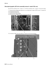
5022-xxx Electrophotographic (EP) drive assembly removal-model C52x only See "EP drive assembly, C52x" on page 7-7 or "EP drive assembly, C53x" on page 4-65. 2. Remove the low voltage power supply. See "Low voltage power supply (LVPS) removal" on page 7-7 for the part number. 1. Disconnect JCART1 (B) and JCART2 (C) connectors from the system card. 6. Open the top access door. 3. Disconnect the JTRANS2 connector (A) from the drive assembly. B C 4-48 Service Manual Open the front access door. 4. Remove all the toner cartridges. 5.
5022-xxx Electrophotographic (EP) drive assembly removal-model C52x only See "EP drive assembly, C52x" on page 7-7 or "EP drive assembly, C53x" on page 4-65. 2. Remove the low voltage power supply. See "Low voltage power supply (LVPS) removal" on page 7-7 for the part number. 1. Disconnect JCART1 (B) and JCART2 (C) connectors from the system card. 6. Open the top access door. 3. Disconnect the JTRANS2 connector (A) from the drive assembly. B C 4-48 Service Manual Open the front access door. 4. Remove all the toner cartridges. 5.

Service Manual
Page 187
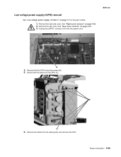
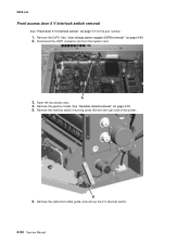
Disconnect the JINT1 connector (A) from cable guide, and remove the 5 V interlock switch. 4-54 Service Manual Remove the LVPS. See "Low voltage power supply (LVPS) removal" on page 7-7 for the part number. 1. Remove the cable from the system card. 5022-xxx Front access door 5 V interlock switch removal See "Front door 5 V interlock switch" on page 4-65. 2. Remove the gearbox shield. Remove the interlock switch mounting screw (B) from the right side of the printer. B 6. A 3. Open the top access door. 4. See "Gearbox shield removal" on page 4-19. 5.
Disconnect the JINT1 connector (A) from cable guide, and remove the 5 V interlock switch. 4-54 Service Manual Remove the LVPS. See "Low voltage power supply (LVPS) removal" on page 7-7 for the part number. 1. Remove the cable from the system card. 5022-xxx Front access door 5 V interlock switch removal See "Front door 5 V interlock switch" on page 4-65. 2. Remove the gearbox shield. Remove the interlock switch mounting screw (B) from the right side of the printer. B 6. A 3. Open the top access door. 4. See "Gearbox shield removal" on page 4-19. 5.
Service Manual
Page 198
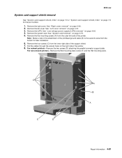
B C 6. Low voltage power supply (LVPS) removal See "Low voltage power supply, 115/230 V" on page 4-26. 2. Remove the rear cover. Unplug the JLVPS1 connector (A) from the cable guide, and remove the LVPS. Repair information 4-65 Remove the five LVPS mounting screws (B). 5. Remove the cable from the system card. 5022-xxx A 4. See "Right cover removal" on page 7-7 for the part number. 1. Disconnect the cable from the LVPS (C). See "Rear cover removal" on page 4-25. 3. Remove the right side cover.
B C 6. Low voltage power supply (LVPS) removal See "Low voltage power supply, 115/230 V" on page 4-26. 2. Remove the rear cover. Unplug the JLVPS1 connector (A) from the cable guide, and remove the LVPS. Repair information 4-65 Remove the five LVPS mounting screws (B). 5. Remove the cable from the system card. 5022-xxx A 4. See "Right cover removal" on page 7-7 for the part number. 1. Disconnect the cable from the LVPS (C). See "Rear cover removal" on page 4-25. 3. Remove the right side cover.
Service Manual
Page 214
... System card support shield removal See "System card support shield, C52x" on page 7-9 or "System card support shield, C53x" on page 7-9 for later installation. 6. See "Low voltage power supply (LVPS) removal" on page 4-65. 4. Note: Make a note of the attachment of the printer.
... System card support shield removal See "System card support shield, C52x" on page 7-9 or "System card support shield, C53x" on page 7-9 for later installation. 6. See "Low voltage power supply (LVPS) removal" on page 4-65. 4. Note: Make a note of the attachment of the printer.
Service Manual
Page 228
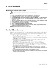
...: Read the following precautions whenever you are not working with ESD-sensitive parts when cold-weather heating is used, because low humidity increases static electricity. Handling ESD-sensitive parts Many electronic products use care not to allow your wrist. 4. This discharges... cabinet (case). • Be extra careful in working on a table. • If possible, keep all the usual precautions, such as the high-voltage power supply. • After part replacement, ensure the wiring harness is not caught or damaged. • Do not attempt to cut or extend the wiring harness...
...: Read the following precautions whenever you are not working with ESD-sensitive parts when cold-weather heating is used, because low humidity increases static electricity. Handling ESD-sensitive parts Many electronic products use care not to allow your wrist. 4. This discharges... cabinet (case). • Be extra careful in working on a table. • If possible, keep all the usual precautions, such as the high-voltage power supply. • After part replacement, ensure the wiring harness is not caught or damaged. • Do not attempt to cut or extend the wiring harness...

Service Manual
Page 275
5022-xxx Electrophotographic (EP) drive assembly removal-model C52x only See "EP drive assembly, C52x" on page 7-7 or "EP drive assembly, C53x" on page 4-65. 2. B C 4-48 Service Manual Remove the low voltage power supply. Remove all the toner cartridges. 5. Open the front access door. 4. Disconnect JCART1 (B) and JCART2 (C) connectors from the system card. 6. Open the top access door. 3. See "Low voltage power supply (LVPS) removal" on page 7-7 for the part number. 1. Disconnect the JTRANS2 connector (A) from the drive assembly.
5022-xxx Electrophotographic (EP) drive assembly removal-model C52x only See "EP drive assembly, C52x" on page 7-7 or "EP drive assembly, C53x" on page 4-65. 2. B C 4-48 Service Manual Remove the low voltage power supply. Remove all the toner cartridges. 5. Open the front access door. 4. Disconnect JCART1 (B) and JCART2 (C) connectors from the system card. 6. Open the top access door. 3. See "Low voltage power supply (LVPS) removal" on page 7-7 for the part number. 1. Disconnect the JTRANS2 connector (A) from the drive assembly.
Service Manual
Page 281
5022-xxx Front access door 5 V interlock switch removal See "Front door 5 V interlock switch" on page 4-65. 2. Remove the LVPS. Open the top access door. 4. B 6. A 3. See "Low voltage power supply (LVPS) removal" on page 7-7 for the part number. 1. Remove the cable from the right side of the printer. Remove the interlock switch mounting screw (B) from cable guide, and remove the 5 V interlock switch. 4-54 Service Manual Remove the gearbox shield. See "Gearbox shield removal" on page 4-19. 5. Disconnect the JINT1 connector (A) from the system card.
5022-xxx Front access door 5 V interlock switch removal See "Front door 5 V interlock switch" on page 4-65. 2. Remove the LVPS. Open the top access door. 4. B 6. A 3. See "Low voltage power supply (LVPS) removal" on page 7-7 for the part number. 1. Remove the cable from the right side of the printer. Remove the interlock switch mounting screw (B) from cable guide, and remove the 5 V interlock switch. 4-54 Service Manual Remove the gearbox shield. See "Gearbox shield removal" on page 4-19. 5. Disconnect the JINT1 connector (A) from the system card.

Service Manual
Page 292
Remove the right side cover. Remove the rear cover. Remove the five LVPS mounting screws (B). 5. Remove the cable from the system card. 5022-xxx A 4. Repair information 4-65 See "Right cover removal" on page 4-25. 3. Unplug the JLVPS1 connector (A) from the cable guide, and remove the LVPS. See "Rear cover removal" on page 4-26. 2. B C 6. Low voltage power supply (LVPS) removal See "Low voltage power supply, 115/230 V" on page 7-7 for the part number. 1. Disconnect the cable from the LVPS (C).
Remove the right side cover. Remove the rear cover. Remove the five LVPS mounting screws (B). 5. Remove the cable from the system card. 5022-xxx A 4. Repair information 4-65 See "Right cover removal" on page 4-25. 3. Unplug the JLVPS1 connector (A) from the cable guide, and remove the LVPS. See "Rear cover removal" on page 4-26. 2. B C 6. Low voltage power supply (LVPS) removal See "Low voltage power supply, 115/230 V" on page 7-7 for the part number. 1. Disconnect the cable from the LVPS (C).

Service Manual
Page 308
... the bottom for the part number. 1. Remove the left side of the printhead ground cable (B) to the second screw from the outer left cover. See "Low voltage power supply (LVPS) removal" on page 4-20. 3. Remove the four screws (C) from the inner right side of the printer. 8. 5022-xxx System card support shield removal See...
... the bottom for the part number. 1. Remove the left side of the printhead ground cable (B) to the second screw from the outer left cover. See "Low voltage power supply (LVPS) removal" on page 4-20. 3. Remove the four screws (C) from the inner right side of the printer. 8. 5022-xxx System card support shield removal See...

Service Manual
Page 354
Assembly 3: Right Index 3-1 1 2 3 4 NS P/N 40X1409 40X3578 40X3574 40X1433 40X1436 40X1445 Units/ mach 1 1 1 1 1 1 Units/ FRU 1 1 1 1 1 1 Description EP drive assembly, C52x EP drive assembly, C53x Low voltage power supply, 115/230 V Bump aligner motor Front door 5 V interlock switch Ground contact plate, C52x only 5022-xxx Parts catalog 7-7
Assembly 3: Right Index 3-1 1 2 3 4 NS P/N 40X1409 40X3578 40X3574 40X1433 40X1436 40X1445 Units/ mach 1 1 1 1 1 1 Units/ FRU 1 1 1 1 1 1 Description EP drive assembly, C52x EP drive assembly, C53x Low voltage power supply, 115/230 V Bump aligner motor Front door 5 V interlock switch Ground contact plate, C52x only 5022-xxx Parts catalog 7-7

Service Manual
Page 370
removal 4-60 Reset Fuser Cnt 3-21 Fuser Motor Test 3-8 H high voltage power supply (HVPS) locations 5-5 parts catalog 7-10 removal 4-62 how to use this parts catalog 7-1 J jams common messages (diagram) 3-27 paper jam messages ... 5-1 CRUs and FRUs 5-7 front 5-2 left 5-5 machine type label 1-13 motors 5-9 printer cards 5-10 rear 5-4 right 5-3 sensors 5-8 serial number label 1-13 top 5-6 low voltage power supply (LVPS) locations 5-3 parts catalog 7-6 removal 4-65 M machine type tag location 1-13 maintenance approach 1-1 mechanical drive bump aligner drive 3-38 duplex drive 3-41 fuser drive 3-40...
removal 4-60 Reset Fuser Cnt 3-21 Fuser Motor Test 3-8 H high voltage power supply (HVPS) locations 5-5 parts catalog 7-10 removal 4-62 how to use this parts catalog 7-1 J jams common messages (diagram) 3-27 paper jam messages ... 5-1 CRUs and FRUs 5-7 front 5-2 left 5-5 machine type label 1-13 motors 5-9 printer cards 5-10 rear 5-4 right 5-3 sensors 5-8 serial number label 1-13 top 5-6 low voltage power supply (LVPS) locations 5-3 parts catalog 7-6 removal 4-65 M machine type tag location 1-13 maintenance approach 1-1 mechanical drive bump aligner drive 3-38 duplex drive 3-41 fuser drive 3-40...
Service Manual
Page 371
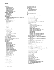
... door 5 V interlock switch 4-54 front door assembly 4-55 front door assembly restraint cable 4-59 fuser 4-60 fuser cable cover 4-61 high voltage power supply (HVPS) 4-62 left cover 4-20 operator panel assembly 4-23 operator panel inner bezel-C52x 4-22 operator panel outer bezel 4-21 rear cover ...springs-C53x 4-42 contact springs 4-44 covers exit tray cover 4-15 front access cover assembly 4-16 gearbox shield 4-19 left bellcrank 4-64 low voltage power supply (LVPS) 4-65 multipurpose feeder (MPF) swing arm assembly-C52x only 4-67 paper pick mechanism assembly 4-68 paper tray dust cover 4-24...
... door 5 V interlock switch 4-54 front door assembly 4-55 front door assembly restraint cable 4-59 fuser 4-60 fuser cable cover 4-61 high voltage power supply (HVPS) 4-62 left cover 4-20 operator panel assembly 4-23 operator panel inner bezel-C52x 4-22 operator panel outer bezel 4-21 rear cover ...springs-C53x 4-42 contact springs 4-44 covers exit tray cover 4-15 front access cover assembly 4-16 gearbox shield 4-19 left bellcrank 4-64 low voltage power supply (LVPS) 4-65 multipurpose feeder (MPF) swing arm assembly-C52x only 4-67 paper pick mechanism assembly 4-68 paper tray dust cover 4-24...
Service Manual
Page 375
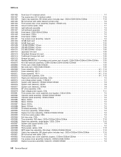
...V 6-1, 7-15 Fuser assembly, 100 V 6-1, 7-15 Transfer belt assembly, C53x 6-1, 7-15 Paper pick mechanism assembly, C53x 7-5 Low voltage power supply, 115/230 V 7-7 System card (network), C530dn/C532n/C532dn 7-9 System card (network), C534n 7-9 System card (network), C534dn 7-9 EP drive assembly, C53x... 7-7 High voltage power supply, C53x 7-11 Front access door cover assembly (non-duplex), C532n/C534n 7-3 Operator panel assembly, C530dn/C532n/C532dn 7-3 Operator panel...
...V 6-1, 7-15 Fuser assembly, 100 V 6-1, 7-15 Transfer belt assembly, C53x 6-1, 7-15 Paper pick mechanism assembly, C53x 7-5 Low voltage power supply, 115/230 V 7-7 System card (network), C530dn/C532n/C532dn 7-9 System card (network), C534n 7-9 System card (network), C534dn 7-9 EP drive assembly, C53x... 7-7 High voltage power supply, C53x 7-11 Front access door cover assembly (non-duplex), C532n/C534n 7-3 Operator panel assembly, C530dn/C532n/C532dn 7-3 Operator panel...


