
Service Manual
Page 3
...1-1 Description 1-1 Specifications 1-3 Recommended Machine Usage 1-3 Options 1-4 Tools 1-4 Abbreviations 1-5 Setup Mode 1-6 How To Change The Printer Functions 1-6 Serial Interface Adapters 1-7 Serial Interface Switches 1-8 Function Switch Setting 1-8 Diagnostic Information 2-1 Start 2-1 Voltage, Ground,... 2-14 Auto Sheet Feeder (ASF) Service Check 2-15 Carrier Drive, Home Position Sensor, Ribbon Feed Service Check 2-17 Intermittent Problem Service Check 2-20 No Print or Abnormal Print Service ...2-38 Top of Forms Problem Service Check 2-39 Tractor 2 Service Check 2-40 Contents v
...1-1 Description 1-1 Specifications 1-3 Recommended Machine Usage 1-3 Options 1-4 Tools 1-4 Abbreviations 1-5 Setup Mode 1-6 How To Change The Printer Functions 1-6 Serial Interface Adapters 1-7 Serial Interface Switches 1-8 Function Switch Setting 1-8 Diagnostic Information 2-1 Start 2-1 Voltage, Ground,... 2-14 Auto Sheet Feeder (ASF) Service Check 2-15 Carrier Drive, Home Position Sensor, Ribbon Feed Service Check 2-17 Intermittent Problem Service Check 2-20 No Print or Abnormal Print Service ...2-38 Top of Forms Problem Service Check 2-39 Tractor 2 Service Check 2-40 Contents v
Service Manual
Page 15
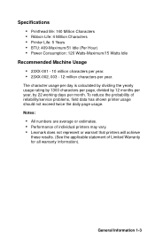
.... • Performance of individual printers may vary. • Lexmark does not represent or warrant that printers will achieve these results. (See the applicable statement of reliability/service problems, field data has shown printer usage should not exceed twice the daily page usage. Specifications • Printhead life: 140 Million Characters • Ribbon Life: 4 Million Characters •...
.... • Performance of individual printers may vary. • Lexmark does not represent or warrant that printers will achieve these results. (See the applicable statement of reliability/service problems, field data has shown printer usage should not exceed twice the daily page usage. Specifications • Printhead life: 140 Million Characters • Ribbon Life: 4 Million Characters •...
Service Manual
Page 27
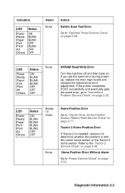
... the "Tractor 2 Service Check" on page 2-32. Refer to "Power Service Check" on page 2-40. If the printer completes POST successfully and eventually gets the same error, go to "Carrier Drive, Home Position Sensor, Ribbon Feed Service Check" on page 2-20. LED Power Ready Paper Font Pitch Alt Others Status ON BLINK...
... the "Tractor 2 Service Check" on page 2-32. Refer to "Power Service Check" on page 2-40. If the printer completes POST successfully and eventually gets the same error, go to "Carrier Drive, Home Position Sensor, Ribbon Feed Service Check" on page 2-20. LED Power Ready Paper Font Pitch Alt Others Status ON BLINK...

Service Manual
Page 30
...interface cable. Go to the "POST Service Check" on page 2-17. The Power light is created. Action Disconnect the interface cable from the printer and turn off and then on. If POST now runs correctly, the problem is created. Go to "Abnormal Noise Service Check" on , but... . During idling, abnormal noise comes from the carrier. Abnormal Noise Problems Symptom During POST, abnormal noise comes from the printer. Action Check the ribbon cartridge for binds or damage. Symptom/Check Table 1. When feeding paper, abnormal noise is on page 2-14. 2-6 Go to the indicated service...
...interface cable. Go to the "POST Service Check" on page 2-17. The Power light is created. Action Disconnect the interface cable from the printer and turn off and then on. If POST now runs correctly, the problem is created. Go to "Abnormal Noise Service Check" on , but... . During idling, abnormal noise comes from the carrier. Abnormal Noise Problems Symptom During POST, abnormal noise comes from the printer. Action Check the ribbon cartridge for binds or damage. Symptom/Check Table 1. When feeding paper, abnormal noise is on page 2-14. 2-6 Go to the indicated service...

Service Manual
Page 38
Service Checks Abnormal Noise Service Check Check the entire printer for the problem in the paper feed mechanism. 2-14 FRU 1 Ribbon Cartridge 2 Printhead 3 Carrier Motor Ribbon Drive Mechanism 4 Paper Feed Mechanism Action Remove and reinstall the ribbon cartridge. Disconnect the printhead cables. Disconnect the carrier motor connector ...CN9 from the main logic board. If the abnormal noise is gone, look for a problem with the carrier motor or ribbon drive mechanism. Run the print test (do not fold or damage the cables during the test). Replace the printhead if the noise...
Service Checks Abnormal Noise Service Check Check the entire printer for the problem in the paper feed mechanism. 2-14 FRU 1 Ribbon Cartridge 2 Printhead 3 Carrier Motor Ribbon Drive Mechanism 4 Paper Feed Mechanism Action Remove and reinstall the ribbon cartridge. Disconnect the printhead cables. Disconnect the carrier motor connector ...CN9 from the main logic board. If the abnormal noise is gone, look for a problem with the carrier motor or ribbon drive mechanism. Run the print test (do not fold or damage the cables during the test). Replace the printhead if the noise...

Service Manual
Page 41
If this area is below the paperfeed motor. Diagnostic Information 2-17 Turn the printer off and then on the main logic board near the paper empty sensor. A ... • The sensor is not quickly opened. • The sensor is closed any time other than when the printer is open, replace the main logic board. If this fuse is turned off and then on, inspect the area ... fuse FU1 located on . Also check the continuity of dots), or if the carrier does not move slightly away from the sensor. Carrier Drive, Home Position Sensor, Ribbon Feed Service Check 23XX-001 only: If the carrier stops...
If this area is below the paperfeed motor. Diagnostic Information 2-17 Turn the printer off and then on the main logic board near the paper empty sensor. A ... • The sensor is not quickly opened. • The sensor is closed any time other than when the printer is open, replace the main logic board. If this fuse is turned off and then on, inspect the area ... fuse FU1 located on . Also check the continuity of dots), or if the carrier does not move slightly away from the sensor. Carrier Drive, Home Position Sensor, Ribbon Feed Service Check 23XX-001 only: If the carrier stops...
Service Manual
Page 45
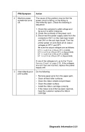
...GND) CP 1-3 (+5 V dc ±5%) & CP1-4 (Signal GND) If one of life has been reached, have the customer replace the ribbon cartridge. Turn the printer power on the sub logic board. Check the customer's outlet voltage and be that the power circuit is failing, or the wiring is intermittently...logic board and CN1 on and check all feed roller surfaces. • Clean the ribbon shield and printhead. • Clean the platen surface. • Install the ribbon cartridge correctly. • If the ribbon end of the voltages is within tolerance. 2. FRU/Symptom 2 Machine power sometimes ...
...GND) CP 1-3 (+5 V dc ±5%) & CP1-4 (Signal GND) If one of life has been reached, have the customer replace the ribbon cartridge. Turn the printer power on the sub logic board. Check the customer's outlet voltage and be that the power circuit is failing, or the wiring is intermittently...logic board and CN1 on and check all feed roller surfaces. • Clean the ribbon shield and printhead. • Clean the platen surface. • Install the ribbon cartridge correctly. • If the ribbon end of the voltages is within tolerance. 2. FRU/Symptom 2 Machine power sometimes ...

Service Manual
Page 76
... CAUTION: Be sure to -platen gap adjustment after replacing or disassembling any of the following parts: • Carrier • Platen • Pinch Roller (Lower) • Ribbon Drive Rack Gear • Side Frame (Left) • Side Frame (Right) • Paper Separator • Feed Roller (Lower) • Paper Guide. Perform the printhead-to...
... CAUTION: Be sure to -platen gap adjustment after replacing or disassembling any of the following parts: • Carrier • Platen • Pinch Roller (Lower) • Ribbon Drive Rack Gear • Side Frame (Left) • Side Frame (Right) • Paper Separator • Feed Roller (Lower) • Paper Guide. Perform the printhead-to...

Service Manual
Page 77
Set the form thickness lever to insert the 0.40 mm (0.016 in . Move the carrier so that it is between the printhead [3] and platen [4] is just to the ... mm - 0.40 mm (0.014 in. - 0.016 in .) from the left upper feed roller, approximately 50 mm (2.0 in .). Remove the ribbon access cover. 3. Repair Information 4-3 1. Remove the ribbon cartridge and paper. 4. Turn the printer off. 2. Note: The gap should be wide enough for the 0.35 mm (0.014 in.) feeler gauge to slide in smoothly...
Set the form thickness lever to insert the 0.40 mm (0.016 in . Move the carrier so that it is between the printhead [3] and platen [4] is just to the ... mm - 0.40 mm (0.014 in. - 0.016 in .) from the left upper feed roller, approximately 50 mm (2.0 in .). Remove the ribbon access cover. 3. Repair Information 4-3 1. Remove the ribbon cartridge and paper. 4. Turn the printer off. 2. Note: The gap should be wide enough for the 0.35 mm (0.014 in.) feeler gauge to slide in smoothly...

Service Manual
Page 79
Turn the printer on. 3. Press the Control Options button. (Button varies with model.) 6. The second and fourth lines are installed. 2. Be sure the ribbon cartridge and continuous forms are printed from left . Press the Bidirectional Alignment button. (Button varies with model.) 5. ...Bidirectional Print Adjustment After replacing any mechanical part which affects the operation of paper, so be completed if the printer runs out ...
Turn the printer on. 3. Press the Control Options button. (Button varies with model.) 6. The second and fourth lines are installed. 2. Be sure the ribbon cartridge and continuous forms are printed from left . Press the Bidirectional Alignment button. (Button varies with model.) 5. ...Bidirectional Print Adjustment After replacing any mechanical part which affects the operation of paper, so be completed if the printer runs out ...

Service Manual
Page 87
...present on page 4-2. Be sure to lose the oil felt [14]. 15. Release the ground spring [11] from the printer. Do not to get the carrier shaft correctly through the oil felt. 16. Repair Information 4-13 Perform the Printhead-to...carrier bushing. 12. the spring need not be removed. 11. Release the latch [8] and slide the carrier shaft and forms thickness lever to -Platen Gap Adjustment" on all machines). 13. 10. Rotate the left and remove them together from ...Do not to lose the gap set collar [15] attached to disengage the carrier ribbon drive gears, then remove the carrier.
...present on page 4-2. Be sure to lose the oil felt [14]. 15. Release the ground spring [11] from the printer. Do not to get the carrier shaft correctly through the oil felt. 16. Repair Information 4-13 Perform the Printhead-to...carrier bushing. 12. the spring need not be removed. 11. Release the latch [8] and slide the carrier shaft and forms thickness lever to -Platen Gap Adjustment" on all machines). 13. 10. Rotate the left and remove them together from ...Do not to lose the gap set collar [15] attached to disengage the carrier ribbon drive gears, then remove the carrier.

Service Manual
Page 122
... aligned and secured. Before you remove the printhead, set the form thickness lever to move the carrier. 3. Printhead Removal 1. Disconnect the power cord at the printer. • Let the printhead cool for 15 minutes before touching it from the printhead connector. Remove the ribbon cartridge. 6. Disconnect the printhead cables [2] from the right side...
... aligned and secured. Before you remove the printhead, set the form thickness lever to move the carrier. 3. Printhead Removal 1. Disconnect the power cord at the printer. • Let the printhead cool for 15 minutes before touching it from the printhead connector. Remove the ribbon cartridge. 6. Disconnect the printhead cables [2] from the right side...

Service Manual
Page 135
Top Cover Removal 1. Disconnect the power cord at the printer. 3. 23XX-001 - Remove the front cover [2] and the ribbon access cover [3]. 6. Insert a flat blade screwdriver into each of the five holes in the pull tractor position, remove the tractor assembly see "Pull ...secure the top cover [5] to the bottom cover [6]. Remove the two screws [8]. 9. Repair Information 4-61 Turn the printer off. 2. Remove the paper advance knob [1] by pulling to the cut sheet position. 8. Stand the printer on page 4-50. 5. Set the paper select lever [4] to the right. 4. Release the two latches [9], ...
Top Cover Removal 1. Disconnect the power cord at the printer. 3. 23XX-001 - Remove the front cover [2] and the ribbon access cover [3]. 6. Insert a flat blade screwdriver into each of the five holes in the pull tractor position, remove the tractor assembly see "Pull ...secure the top cover [5] to the bottom cover [6]. Remove the two screws [8]. 9. Repair Information 4-61 Turn the printer off. 2. Remove the paper advance knob [1] by pulling to the cut sheet position. 8. Stand the printer on page 4-50. 5. Set the paper select lever [4] to the right. 4. Release the two latches [9], ...

Service Manual
Page 141
Connector Locations This chapter shows the locations of specific parts of the printer. Reference A B C D E F G H I J K L M N O P Q R S T U V W Part Name Form Thickness Lever Paper Select Lever Carrier Motor Paper Feed Motor Parallel Interface Connector Main Logic Board Sub Logic Board Power Supply Tractor Unit Pull Tractor Actuator Ribbon Cartridge Ribbon Drive Rack Gear Pinch Roller, Lower Feed Roller, Lower Printhead Printhead Cables Carrier Tension Pulley Plate Feed Roller, Upper Platen Side Frame, Right Side Frame, Left Carrier Plate Connector Locations 5-1 5.
Connector Locations This chapter shows the locations of specific parts of the printer. Reference A B C D E F G H I J K L M N O P Q R S T U V W Part Name Form Thickness Lever Paper Select Lever Carrier Motor Paper Feed Motor Parallel Interface Connector Main Logic Board Sub Logic Board Power Supply Tractor Unit Pull Tractor Actuator Ribbon Cartridge Ribbon Drive Rack Gear Pinch Roller, Lower Feed Roller, Lower Printhead Printhead Cables Carrier Tension Pulley Plate Feed Roller, Upper Platen Side Frame, Right Side Frame, Left Carrier Plate Connector Locations 5-1 5.


