
Service Manual
Page 2
... ...4 Safety Precautions...5 Dimensions...11 Indoor Unit...11 Outdoor Unit ...12 Product Specifications ...13 Installation ...15 Installation Parts...15 Installation Tools...15 Select the best location ...16 Piping length and elevation ...17 Fixing Installation Plate(Standart Type 18 Preparing work for Installation (Artcool Type Only 19 Flaring Work and Connection of Piping 21 Flaring work...21...
... ...4 Safety Precautions...5 Dimensions...11 Indoor Unit...11 Outdoor Unit ...12 Product Specifications ...13 Installation ...15 Installation Parts...15 Installation Tools...15 Select the best location ...16 Piping length and elevation ...17 Fixing Installation Plate(Standart Type 18 Preparing work for Installation (Artcool Type Only 19 Flaring Work and Connection of Piping 21 Flaring work...21...
Service Manual
Page 5
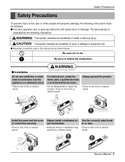
... injury or damage to properties only. CAUTION This symbol indicates the possibility of control box securely. rated circuit breaker. Install the panel and the cover Always install a dedicated cir- There is risk of fire or electric shock. • There is risk of fire or electric... shock. • Improper wiring or installation may • There is classified by the following instructions must be followed. Service Manual 5 WARNING s Installation Do not use a defective or under- Be sure to follow the instruction. Safety ...
... injury or damage to properties only. CAUTION This symbol indicates the possibility of control box securely. rated circuit breaker. Install the panel and the cover Always install a dedicated cir- There is risk of fire or electric shock. • There is risk of fire or electric... shock. • Improper wiring or installation may • There is classified by the following instructions must be followed. Service Manual 5 WARNING s Installation Do not use a defective or under- Be sure to follow the instruction. Safety ...
Service Manual
Page 6
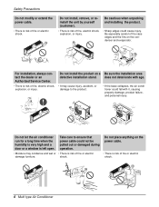
... Precautions Do not modify or extend the power cable. • There is risk of fire, electric shock, explosion, or injury. Do not install, remove, or reinstall the unit by yourself (customer). • There is left open. shock. does not deteriorate with it, causing property... damage, product failure, and personal injury. Do not place anything on a Be sure the installation area defective installation stand. Take care to ensure that power cable could not be pulled out or damaged during operation. • Moisture may cause ...
... Precautions Do not modify or extend the power cable. • There is risk of fire, electric shock, explosion, or injury. Do not install, remove, or reinstall the unit by yourself (customer). • There is left open. shock. does not deteriorate with it, causing property... damage, product failure, and personal injury. Do not place anything on a Be sure the installation area defective installation stand. Take care to ensure that power cable could not be pulled out or damaged during operation. • Moisture may cause ...
Service Manual
Page 8
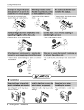
...- Safety Precautions Do not open the inlet grill of the product When the product is risk of fire, electric shock, or product damage. ed operation. s Installation CAUTION Always check for a long time, dis- Take care to ensure that Keep level even when age after... product. • Low refrigerant levels may cause • A bad connection may cause water • To avoid vibration or water leak- Install the drain hose to time when operating it together with a stove, etc. • There is risk of product. leakage. trostatic filter, if the unit is ...
...- Safety Precautions Do not open the inlet grill of the product When the product is risk of fire, electric shock, or product damage. ed operation. s Installation CAUTION Always check for a long time, dis- Take care to ensure that Keep level even when age after... product. • Low refrigerant levels may cause • A bad connection may cause water • To avoid vibration or water leak- Install the drain hose to time when operating it together with a stove, etc. • There is risk of product. leakage. trostatic filter, if the unit is ...
Service Manual
Page 9
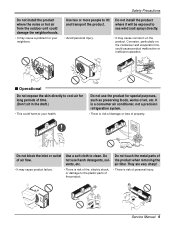
... of air flow. Wax Thinner Service Manual 9 Do not block the inlet or outlet of the product when removing the air filter. Do not install the product where it will be exposed to cool air for special purposes, such as preserving foods, works of time. (Don't sit in the...harsh detergents, solvents, etc. It is a consumer air conditioner, not a precision refrigeration system. • There is risk of property. Safety Precautions Do not install the product where the noise or hot air from the outdoor unit could damage the neighborhoods. • It may cause a problem for your health.
... of air flow. Wax Thinner Service Manual 9 Do not block the inlet or outlet of the product when removing the air filter. Do not install the product where it will be exposed to cool air for special purposes, such as preserving foods, works of time. (Don't sit in the...harsh detergents, solvents, etc. It is a consumer air conditioner, not a precision refrigeration system. • There is risk of property. Safety Precautions Do not install the product where the noise or hot air from the outdoor unit could damage the neighborhoods. • It may cause a problem for your health.

Service Manual
Page 11
Art Cool Type Indoor Unit W D H Pipe Hole Hanger Hole Installation plate Fix Hole Dimension W H D Model mm mm mm Split Type S4 SE 9 kBtu/h 12 kBtu/h 840 895 270 282 153 165 ARTCOOL Type SP3 9 kBtu/h 12 kBtu/h 570 568 129 Service Manual 11 Dimensions Indoor Unit 1. Split Type Indoor H D W Dimensions 2.
Art Cool Type Indoor Unit W D H Pipe Hole Hanger Hole Installation plate Fix Hole Dimension W H D Model mm mm mm Split Type S4 SE 9 kBtu/h 12 kBtu/h 840 895 270 282 153 165 ARTCOOL Type SP3 9 kBtu/h 12 kBtu/h 570 568 129 Service Manual 11 Dimensions Indoor Unit 1. Split Type Indoor H D W Dimensions 2.
Service Manual
Page 14
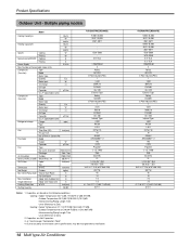
... W Capacitor µF/Vac Fan Type No. Capacities are Net Capacities. 3. 5 : See the page "Combination Table" 4. Installation Indoor Unit~Outdoor Unit m Height Difference Indoor Unit~Indoor Unit m Packing Dimension W*H*D inch(mm) Stuffing Quantity 20/40ft A3UC363FA0(LMU360CE) 9,000~36,000 2637~10,550 2267~9071 1320~3680 5.9~16.6 1,208/230,60 3 Rotary GK141K...
... W Capacitor µF/Vac Fan Type No. Capacities are Net Capacities. 3. 5 : See the page "Combination Table" 4. Installation Indoor Unit~Outdoor Unit m Height Difference Indoor Unit~Indoor Unit m Packing Dimension W*H*D inch(mm) Stuffing Quantity 20/40ft A3UC363FA0(LMU360CE) 9,000~36,000 2637~10,550 2267~9071 1320~3680 5.9~16.6 1,208/230,60 3 Rotary GK141K...
Service Manual
Page 15
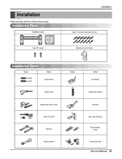
Installation Read carefully, and then follow step by step. Installation Parts Installation plate Type "B" screw Installation Type "A" screw and plastic anchor Remote Control Holder Installation Tools Figure Name Screw driver Electric Drill Measuring Tape, Knife Hole Core Drill Spanner Torque wrench Figure Name Ohmmeter Hexagonal wrench Ammeter Gas Leak Detector Thermometer, Level Flaring Tool Set Service Manual 15
Installation Read carefully, and then follow step by step. Installation Parts Installation plate Type "B" screw Installation Type "A" screw and plastic anchor Remote Control Holder Installation Tools Figure Name Screw driver Electric Drill Measuring Tape, Knife Hole Core Drill Spanner Torque wrench Figure Name Ohmmeter Hexagonal wrench Ammeter Gas Leak Detector Thermometer, Level Flaring Tool Set Service Manual 15
Service Manual
Page 16
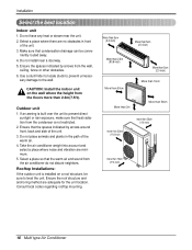
... routed away. 4. Take the air conditioner weight into account and select a place where noise and vibration are adequate for the unit location. Installation Select the best location Indoor unit 1. Ensure that condensation drainage can be sure to prevent direct sunlight or rain exposure, make sure that the... warm air and sound from the floors more than 2.3m(7.5ft). Rooftop Installations: If the outdoor unit is installed on the wall where the height from the air conditioner do not disturb neighbors. If an awning is not restricted. 2....
... routed away. 4. Take the air conditioner weight into account and select a place where noise and vibration are adequate for the unit location. Installation Select the best location Indoor unit 1. Ensure that condensation drainage can be sure to prevent direct sunlight or rain exposure, make sure that the... warm air and sound from the floors more than 2.3m(7.5ft). Rooftop Installations: If the outdoor unit is installed on the wall where the height from the air conditioner do not disturb neighbors. If an awning is not restricted. 2....
Service Manual
Page 17
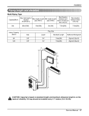
... 5~7 meters (16.4~23.0ft). Service Manual 17 Installation Piping length and elevation Multi Piping Type Capacity(Btu/h) Max total length of all pipes (A+B/A+B+C) Max length of each pipe (A/B/C) Min length of each pipe (A/B/C) ...
... 5~7 meters (16.4~23.0ft). Service Manual 17 Installation Piping length and elevation Multi Piping Type Capacity(Btu/h) Max total length of all pipes (A+B/A+B+C) Max length of each pipe (A/B/C) Min length of each pipe (A/B/C) ...
Service Manual
Page 18
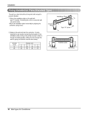
... anchor bolts. • Mount the installation plate horizontally by aligning the centerline using a level. Chassis Hook Installation Plate Type "A" screw 2. Mount the installation plate on a concrete wall, use caution concerning the location of the installation plate-routing of the wiring to power...A B C D S4 50 105 59 105 SE 65 110 85 110 D Installation plate B C Ø70mm Left rear piping A Ø70mm Right rear piping 18 Multi type Air Conditioner Installation Fixing Installation Plate(Standard Type) The wall you select should be done safely. If mounting the ...
... anchor bolts. • Mount the installation plate horizontally by aligning the centerline using a level. Chassis Hook Installation Plate Type "A" screw 2. Mount the installation plate on a concrete wall, use caution concerning the location of the installation plate-routing of the wiring to power...A B C D S4 50 105 59 105 SE 65 110 85 110 D Installation plate B C Ø70mm Left rear piping A Ø70mm Right rear piping 18 Multi type Air Conditioner Installation Fixing Installation Plate(Standard Type) The wall you select should be done safely. If mounting the ...
Service Manual
Page 19
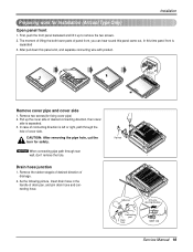
Installation Preparing work for fixing cover pipe) 2. In case of connecting direction is left or right, path through rear wall, don't remove the hole. Pipe hole ... front panel backward and lift it up the cover side of drainage. 2. After pull down this time panel front is separated. 3. Remove two screws(for Installation (Artcool Type Only) Open panel front 1. CAUTION: After removing the pipe hole, cut the burr for safety. Panel Front Connector Remove cover pipe and cover...
Installation Preparing work for fixing cover pipe) 2. In case of connecting direction is left or right, path through rear wall, don't remove the hole. Pipe hole ... front panel backward and lift it up the cover side of drainage. 2. After pull down this time panel front is separated. 3. Remove two screws(for Installation (Artcool Type Only) Open panel front 1. CAUTION: After removing the pipe hole, cut the burr for safety. Panel Front Connector Remove cover pipe and cover...
Service Manual
Page 20
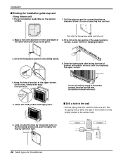
...8226; Drill the piping hole with diameter of 6mm and depth of 30-35mm when piercing a screw point. In case of product) 5. Installation s Sticking the installation guide map and fixing Indoor unit 1. Make a hole with a ø50mm hole core drill. Plastic anchors Plastic anchors 4. Check the ...the upper parts by horizontal meter on this time, Remove the map) (Falling attention) INSTALLATION GUIDE MAP Hanger hole (Rear side of nothing wrong in the matter, connect the pipe and the wire. (Installation manual reference) s Drill a hole in the wall. 8. Look at either the right...
...8226; Drill the piping hole with diameter of 6mm and depth of 30-35mm when piercing a screw point. In case of product) 5. Installation s Sticking the installation guide map and fixing Indoor unit 1. Make a hole with a ø50mm hole core drill. Plastic anchors Plastic anchors 4. Check the ...the upper parts by horizontal meter on this time, Remove the map) (Falling attention) INSTALLATION GUIDE MAP Hanger hole (Rear side of nothing wrong in the matter, connect the pipe and the wire. (Installation manual reference) s Drill a hole in the wall. 8. Look at either the right...
Service Manual
Page 22
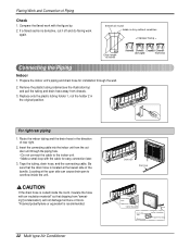
... Piping Check 1. Flaring Work and Connection of the bundle. If a flared section is defective, cut it off and do flaring work with the cable for installation through the piping hole. • Do not connect the cable to overflow inside the room, insulate the hose with an insulation material* so that the...
... Piping Check 1. Flaring Work and Connection of the bundle. If a flared section is defective, cut it off and do flaring work with the cable for installation through the piping hole. • Do not connect the cable to overflow inside the room, insulate the hose with an insulation material* so that the...

Service Manual
Page 23
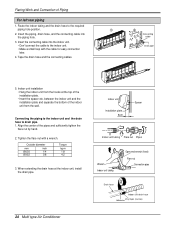
...connection pipe insulation material and the indoor unit pipe insulation material. Bind them with vinyl tape so that the hooks are properly seated on the installation plate by hand. 2. Press the lower left and right. Outside diameter mm inch Ø6.35 1/4 Ø9.52 3/8 Torque kg.m 1.8... 4.2 3. When extending the drain hose at the indoor unit, install the drain pipe. Wrap the area which accommodates the rear piping housing section with a wrench. Bundle the piping and drain hose together by wrapping...
...connection pipe insulation material and the indoor unit pipe insulation material. Bind them with vinyl tape so that the hooks are properly seated on the installation plate by hand. 2. Press the lower left and right. Outside diameter mm inch Ø6.35 1/4 Ø9.52 3/8 Torque kg.m 1.8... 4.2 3. When extending the drain hose at the indoor unit, install the drain pipe. Wrap the area which accommodates the rear piping housing section with a wrench. Bundle the piping and drain hose together by wrapping...
Service Manual
Page 24
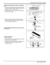
... and separate the bottom of the indoor unit from the hooks at the indoor unit, install the drain pipe. 24 Multi type Air Conditioner Indoor unit Installation plate 8cm Spacer Indoor unit tubing Flare nut Pipes Wrench Indoor unit tubing Open-end wrench (fixed) Flare nut Connection pipe... flare nut with the cable for easy connection later. 4. When extending the drain hose at the top of the installation plate. • Insert the spacer etc. Indoor unit installation • Hang the indoor unit from the wall. Flaring Work and Connection of the pipes and sufficiently tighten the ...
... and separate the bottom of the indoor unit from the hooks at the indoor unit, install the drain pipe. 24 Multi type Air Conditioner Indoor unit Installation plate 8cm Spacer Indoor unit tubing Flare nut Pipes Wrench Indoor unit tubing Open-end wrench (fixed) Flare nut Connection pipe... flare nut with the cable for easy connection later. 4. When extending the drain hose at the top of the installation plate. • Insert the spacer etc. Indoor unit installation • Hang the indoor unit from the wall. Flaring Work and Connection of the pipes and sufficiently tighten the ...
Service Manual
Page 25
... tape(narrow) Wrap with vinyl tape. 3. Press the lower left and right. 3. Flaring Work and Connection of the unit against the installation plate until the hooks engage into the rear piping housing section. Bind them with cloth tape over the range within which accommodates the rear ...piping housing section with vinyl tape(wide) Indoor unit installation 1. Reroute the pipings and the drain hose across the back of the chassis. Remove the spacer. 2. Overlap the connection pipe heat ...
... tape(narrow) Wrap with vinyl tape. 3. Press the lower left and right. 3. Flaring Work and Connection of the unit against the installation plate until the hooks engage into the rear piping housing section. Bind them with cloth tape over the range within which accommodates the rear ...piping housing section with vinyl tape(wide) Indoor unit installation 1. Reroute the pipings and the drain hose across the back of the chassis. Remove the spacer. 2. Overlap the connection pipe heat ...
Service Manual
Page 27
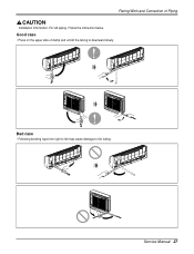
Follow the instruction below. Bad case • Following bending type from right to left piping. Service Manual 27 Good case • Press on the upper side of Piping Installation Information. Flaring Work and Connection of clamp and unfold the tubing to the tubing. For left may cause damage to downward slowly.
Follow the instruction below. Bad case • Following bending type from right to left piping. Service Manual 27 Good case • Press on the upper side of Piping Installation Information. Flaring Work and Connection of clamp and unfold the tubing to the tubing. For left may cause damage to downward slowly.
Service Manual
Page 30
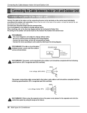
.... 30 Multi type Air Conditioner RECOMMAND: The power cord connected to the electrical diagram behind the front panel of the Outdoor Unit control cover. When installing, refer to the outdoor unit should be found on the control board individually according to change without notice. • Be sure to connect wires according...
.... 30 Multi type Air Conditioner RECOMMAND: The power cord connected to the electrical diagram behind the front panel of the Outdoor Unit control cover. When installing, refer to the outdoor unit should be found on the control board individually according to change without notice. • Be sure to connect wires according...
Service Manual
Page 35
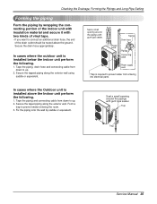
... the exterior wall. Tape the piping, drain hose and connecting cable from down to up . 2. In cases where the Outdoor unit is installed below the indoor unit perform the following . 1. Secure the taped piping along the exterior wall using saddle or equivalent. In cases where the... outdoor unit is installed above the ground. Checking the Drainage, Forming the Pipings and Long Pipe Setting Forming the piping Form the piping by saddle or equivalent. ...
... the exterior wall. Tape the piping, drain hose and connecting cable from down to up . 2. In cases where the Outdoor unit is installed below the indoor unit perform the following . 1. Secure the taped piping along the exterior wall using saddle or equivalent. In cases where the... outdoor unit is installed above the ground. Checking the Drainage, Forming the Pipings and Long Pipe Setting Forming the piping Form the piping by saddle or equivalent. ...


