
Service Manual
Page 2
... of Indoor Unit ...45 Function of Outdoor Unit ...47 Remote Control Operation ...48 Disassembly ...49 Indoor Unit...49 Schematic Diagram...54 Electronic Control Device ...54 Wiring Diagram...58 Components Locations...59 Troubleshooting Guide ...64 Refrigeration Cycle Diagram ...64 Self-diagnosis Function ...65 Cycle Troubleshooting Guide...66 Electronic Parts Troubleshooting Guide 67...
... of Indoor Unit ...45 Function of Outdoor Unit ...47 Remote Control Operation ...48 Disassembly ...49 Indoor Unit...49 Schematic Diagram...54 Electronic Control Device ...54 Wiring Diagram...58 Components Locations...59 Troubleshooting Guide ...64 Refrigeration Cycle Diagram ...64 Self-diagnosis Function ...65 Cycle Troubleshooting Guide...66 Electronic Parts Troubleshooting Guide 67...
Service Manual
Page 5
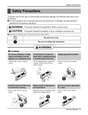
... shock. WARNING This symbol indicates the possibility of injury or damage to properties only. Be sure to do. of fire or electric shock. • Improper wiring or installation may • There is classified by the following instructions must be followed. Install the panel and the cover Always install a dedicated cir- cuit...
... shock. WARNING This symbol indicates the possibility of injury or damage to properties only. Be sure to do. of fire or electric shock. • Improper wiring or installation may • There is classified by the following instructions must be followed. Install the panel and the cover Always install a dedicated cir- cuit...
Service Manual
Page 18
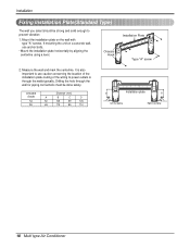
... the wall and mark the centerline. Mount the installation plate on a concrete wall, use caution concerning the location of the installation plate-routing of the wiring to prevent vibration 1.
... the wall and mark the centerline. Mount the installation plate on a concrete wall, use caution concerning the location of the installation plate-routing of the wiring to prevent vibration 1.
Service Manual
Page 19
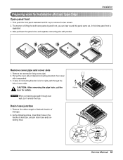
... and lift it up the cover side of panel front, you can hear sound this panel came out, In this panel a bit, and separate connecting wire with product. The moment of lifting the both lower parts of desired connecting direction, then cover side is separated. 3. Pull up to remove the two...
... and lift it up the cover side of panel front, you can hear sound this panel came out, In this panel a bit, and separate connecting wire with product. The moment of lifting the both lower parts of desired connecting direction, then cover side is separated. 3. Pull up to remove the two...
Service Manual
Page 20
... lower parts after facing the hole of product with diameter of 6mm and depth of nothing wrong in the matter, connect the pipe and the wire. (Installation manual reference) s Drill a hole in the wall. 8. Check the fixed product with a ø50mm hole core drill. Drive the fore plastic anchors into drilled...
... lower parts after facing the hole of product with diameter of 6mm and depth of nothing wrong in the matter, connect the pipe and the wire. (Installation manual reference) s Drill a hole in the wall. 8. Check the fixed product with a ø50mm hole core drill. Drive the fore plastic anchors into drilled...
Service Manual
Page 26
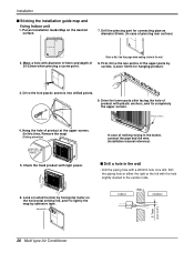
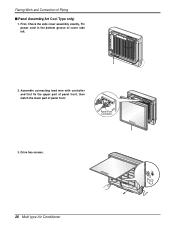
Drive two screws. 26 Multi type Air Conditioner Flaring Work and Connection of cover side left. 2. First, Check the side cover assembly exactly, Fix power cord in the bottom groove of Piping s Panel Assembly(Art Cool Type only) 1. Assemble connecting lead wire with controller and first fix the upper part of panel front, then match the lower part of panel front Panel Front Connector 3.
Drive two screws. 26 Multi type Air Conditioner Flaring Work and Connection of cover side left. 2. First, Check the side cover assembly exactly, Fix power cord in the bottom groove of Piping s Panel Assembly(Art Cool Type only) 1. Assemble connecting lead wire with controller and first fix the upper part of panel front, then match the lower part of panel front Panel Front Connector 3.
Service Manual
Page 30
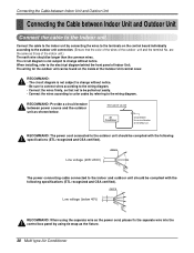
...Multi type Air Conditioner The circuit diagram is not subject to change without notice. • Be sure to connect wires according to the wiring diagram. • Connect the wires firmly, so that not to be found on the control board individually according to the outdoor unit should be longer... by referring to the terminals on the inside of Indoor Unit. The wiring for the outdoor unit can be pulled out easily. • Connect the wires according to color codes by connecting the wires to the wiring diagram. Main power source Air Conditioner Circuit Breaker Use a circuit breaker ...
...Multi type Air Conditioner The circuit diagram is not subject to change without notice. • Be sure to connect wires according to the wiring diagram. • Connect the wires firmly, so that not to be found on the control board individually according to the outdoor unit should be longer... by referring to the terminals on the inside of Indoor Unit. The wiring for the outdoor unit can be pulled out easily. • Connect the wires according to color codes by connecting the wires to the wiring diagram. Main power source Air Conditioner Circuit Breaker Use a circuit breaker ...
Service Manual
Page 31
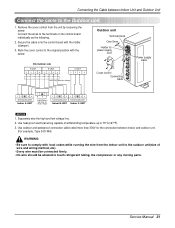
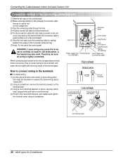
.... 2. Secure the cable onto the control board with the screw. Use heat-proof electrical wiring capable of wire and wiring method, etc). • Every wire must be connected firmly. • No wire should be allowed to the original position with the holder (clamper). 3. Connecting cable(Low ...12 34 Terminal BLOCK Indoor C-UNIT NOTICE : 1. Refix the cover control to touch refrigerant tubing, the compressor or any moving parts. Separately wire the high and low voltage line. 2. Connecting the Cable between indoor and outdoor unit. (For example, Type SJO-WA) WARNING: &#...
.... 2. Secure the cable onto the control board with the screw. Use heat-proof electrical wiring capable of wire and wiring method, etc). • Every wire must be connected firmly. • No wire should be allowed to the original position with the holder (clamper). 3. Connecting cable(Low ...12 34 Terminal BLOCK Indoor C-UNIT NOTICE : 1. Refix the cover control to touch refrigerant tubing, the compressor or any moving parts. Separately wire the high and low voltage line. 2. Connecting the Cable between indoor and outdoor unit. (For example, Type SJO-WA) WARNING: &#...
Service Manual
Page 32
... tool. (for sealing) Power supply line Conduit panel Low voltage line (1ø, 230/208V) (connecting cable) When connecting each stripped wire end with the fixing screw of the terminal plate. Terminal block G Lock nut Cord clamp Cap(Reuse) Hole (for low voltage line... replace and tighten the terminal screw using a screwdriver. How to connect wiring to the terminals s For strand wiring (1) Cut the wire end with a wire cutter or wire-cutting pliers, then strip the insulation to expose the strand wiring about 10mm(3/8"). (2) Using a screwdriver, remove the terminal screw(s) on...
... tool. (for sealing) Power supply line Conduit panel Low voltage line (1ø, 230/208V) (connecting cable) When connecting each stripped wire end with the fixing screw of the terminal plate. Terminal block G Lock nut Cord clamp Cap(Reuse) Hole (for low voltage line... replace and tighten the terminal screw using a screwdriver. How to connect wiring to the terminals s For strand wiring (1) Cut the wire end with a wire cutter or wire-cutting pliers, then strip the insulation to expose the strand wiring about 10mm(3/8"). (2) Using a screwdriver, remove the terminal screw(s) on...
Service Manual
Page 33
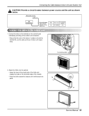
Connect the wires to the terminals on the top inside edge of the chassis. • Press the Grille toward the chassis until it will be back into place. ... Power source Fuse or breaker Capacity 1Ø, 230/208V 40A Connect the cable to the outdoor unit connection. • Ensure that the color of the wires of indoor unit respectively. Main power source Air Conditioner Circuit Breaker Use a circuit breaker or time delay fuse. Connecting cable 2. Connecting the Cable between Indoor...
Connect the wires to the terminals on the top inside edge of the chassis. • Press the Grille toward the chassis until it will be back into place. ... Power source Fuse or breaker Capacity 1Ø, 230/208V 40A Connect the cable to the outdoor unit connection. • Ensure that the color of the wires of indoor unit respectively. Main power source Air Conditioner Circuit Breaker Use a circuit breaker or time delay fuse. Connecting cable 2. Connecting the Cable between Indoor...
Service Manual
Page 36
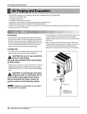
... liquid side service valves. NOTICE : Leakage test shoud be free of the cylinder must always be higher than 150 P.S.I .G. Be sure to corrosion of all wiring for leaks with a clean cloth. 2.
... liquid side service valves. NOTICE : Leakage test shoud be free of the cylinder must always be higher than 150 P.S.I .G. Be sure to corrosion of all wiring for leaks with a clean cloth. 2.
Service Manual
Page 39
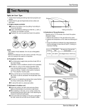
...it leads to be paid. Measure the temperature of the intake and discharge of outdoor unit s Anchor the outdoor unit with a nail or wire assuming the influence of the gas side service valve. Ensure the difference between the intake temperature and the discharge is more than 8°C(46&#...continuously. (Room type) s To cancel the test run , carry out the cooling operation firstly even during heating season. Check that all tubing and wiring have been properly connected. 2. If heating operation is not going to the trouble of the rated voltage. tem is carried out firstly, it back into...
...it leads to be paid. Measure the temperature of the intake and discharge of outdoor unit s Anchor the outdoor unit with a nail or wire assuming the influence of the gas side service valve. Ensure the difference between the intake temperature and the discharge is more than 8°C(46&#...continuously. (Room type) s To cancel the test run , carry out the cooling operation firstly even during heating season. Check that all tubing and wiring have been properly connected. 2. If heating operation is not going to the trouble of the rated voltage. tem is carried out firstly, it back into...
Service Manual
Page 49
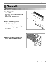
... supply before making any checks. Before removing the control box, be sure to "OFF". Be sure the power switch is set to take out the wire screwed at the other end.
... supply before making any checks. Before removing the control box, be sure to "OFF". Be sure the power switch is set to take out the wire screwed at the other end.

Service Manual
Page 52
... cover control out from the Chassis. - Lift the both lower parts of panel front. - To remove the Grille from the control box and disconnect other wires. - Before removing the control box, be sure to "OFF". 1. Be sure the power switch is set to disconnect the...
... cover control out from the Chassis. - Lift the both lower parts of panel front. - To remove the Grille from the control box and disconnect other wires. - Before removing the control box, be sure to "OFF". 1. Be sure the power switch is set to disconnect the...
Service Manual
Page 58
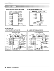
Art Cool Type Indoor Unit 3. Outdoor Unit 1. Schematic Diagram Wiring Diagram 1. A3UC363FA0(LMU360CE) 58 Multi type Air Conditioner A3UH363FA0(LMU360HE) 2. Room Type Indoor Unit -S4/SE chassis 2.
Art Cool Type Indoor Unit 3. Outdoor Unit 1. Schematic Diagram Wiring Diagram 1. A3UC363FA0(LMU360CE) 58 Multi type Air Conditioner A3UH363FA0(LMU360HE) 2. Room Type Indoor Unit -S4/SE chassis 2.
Service Manual
Page 69
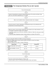
... not (about 10K at least. Check Point Between Micom(No. 50,51) and GND Between IC01M(No. 10) and GND Comp. Check the electrical wiring diagram of the Indoor temperature by 1°C at 25°C). Operate Cooling Mode by the themperature of Heat Exchange (EVA.) When the sensor circuit for...• Check the voltage between brown and blue cable of terminal to connect the Outdoor (About AC208V / 230V). • Check the related circuit of connecting wires between Indoor and Outdoor. When in air circulation mode, compressor/outdoor fan is less than one of Outdoor side. ON DC 5V DC 1V↓...
... not (about 10K at least. Check Point Between Micom(No. 50,51) and GND Between IC01M(No. 10) and GND Comp. Check the electrical wiring diagram of the Indoor temperature by 1°C at 25°C). Operate Cooling Mode by the themperature of Heat Exchange (EVA.) When the sensor circuit for...• Check the voltage between brown and blue cable of terminal to connect the Outdoor (About AC208V / 230V). • Check the related circuit of connecting wires between Indoor and Outdoor. When in air circulation mode, compressor/outdoor fan is less than one of Outdoor side. ON DC 5V DC 1V↓...
Service Manual
Page 70
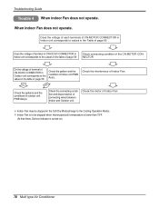
... Indoor unit PWB Ass'y. Check the interference of outdoor unit PWB Assy's. Indoor Fan is to the Cooling Operation Mode). Check the motor of connecting wires between Indoor and Outdoor unit. Troubleshooting Guide Trouble 4 When indoor Fan does not operate. Check the connecting condition and disconnection of Indoor Fan Indoor Fan...
... Indoor unit PWB Ass'y. Check the interference of outdoor unit PWB Assy's. Indoor Fan is to the Cooling Operation Mode). Check the motor of connecting wires between Indoor and Outdoor unit. Troubleshooting Guide Trouble 4 When indoor Fan does not operate. Check the connecting condition and disconnection of Indoor Fan Indoor Fan...
Service Manual
Page 73
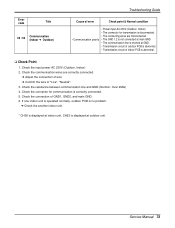
Service Manual 73 Check the communication wires are misconnected. • Communication poorly • The GND 1,2 is not connected at main GND. • The communication line is shorted at outdoor unit. Check the ... GND. • Transmission circuit of outdoor PCB is abnormal. • Transmission circuit of indoor PCB is disconnected. • The connecting wires are correctly connected. ➔ Adjust the connection of wire ➔ Confirm the wire of GND1, GND2, and main GND. 6. Check the connector for transmission is abnormal. ❑ Check Point 1. Check the input...
Service Manual 73 Check the communication wires are misconnected. • Communication poorly • The GND 1,2 is not connected at main GND. • The communication line is shorted at outdoor unit. Check the ... GND. • Transmission circuit of outdoor PCB is abnormal. • Transmission circuit of indoor PCB is disconnected. • The connecting wires are correctly connected. ➔ Adjust the connection of wire ➔ Confirm the wire of GND1, GND2, and main GND. 6. Check the connector for transmission is abnormal. ❑ Check Point 1. Check the input...


