

Service Manual
Page 2
... Model Number Nomenclature ...3 Symbols Used in this Manual ...4 Safety Precautions...5 Dimensions...11 Indoor Unit...11 Outdoor Unit ...12 Product Specifications ...13 Installation ...15 Installation Parts...15 Installation Tools...15 Select the best location ...16 Piping length and elevation ...17 Fixing Installation Plate(Standart Type 18 Preparing work for Installation (Artcool Type Only 19 Flaring Work and...
... Model Number Nomenclature ...3 Symbols Used in this Manual ...4 Safety Precautions...5 Dimensions...11 Indoor Unit...11 Outdoor Unit ...12 Product Specifications ...13 Installation ...15 Installation Parts...15 Installation Tools...15 Select the best location ...16 Piping length and elevation ...17 Fixing Installation Plate(Standart Type 18 Preparing work for Installation (Artcool Type Only 19 Flaring Work and...
Service Manual
Page 5
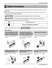
.... er or fuse. • There is risk of fire or electric shock. • Improper wiring or installation may • There is risk of control box securely. Service Manual 5 s Meanings of fire or electric shock. There is risk of fire or electric shock. • There... dealer, seller, a qualified electrician, appliance on a dedicated circuit. For electrical work, contact the Always ground the product. Install the panel and the cover Always install a dedicated cir- Use the correctly rated break- cuit and breaker. Be sure to follow the instruction. rated circuit breaker....
.... er or fuse. • There is risk of fire or electric shock. • Improper wiring or installation may • There is risk of control box securely. Service Manual 5 s Meanings of fire or electric shock. There is risk of fire or electric shock. • There... dealer, seller, a qualified electrician, appliance on a dedicated circuit. For electrical work, contact the Always ground the product. Install the panel and the cover Always install a dedicated cir- Use the correctly rated break- cuit and breaker. Be sure to follow the instruction. rated circuit breaker....
Service Manual
Page 9
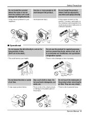
...neighborhoods. • It may cause corrosion on the condenser and evaporator fins, could cause product malfunction or inefficient operation. Safety Precautions Do not install the product where the noise or hot air from the outdoor unit could harm to your neighbors. It is a consumer air conditioner, not... a precision refrigeration system. • There is risk of art, etc. Wax Thinner Service Manual 9 Do not touch the metal parts of air flow. Do not use harsh detergents, solvents, etc. Use two or more people to lift ...
...neighborhoods. • It may cause corrosion on the condenser and evaporator fins, could cause product malfunction or inefficient operation. Safety Precautions Do not install the product where the noise or hot air from the outdoor unit could harm to your neighbors. It is a consumer air conditioner, not... a precision refrigeration system. • There is risk of art, etc. Wax Thinner Service Manual 9 Do not touch the metal parts of air flow. Do not use harsh detergents, solvents, etc. Use two or more people to lift ...

Service Manual
Page 11
Split Type Indoor H D W Dimensions 2. Art Cool Type Indoor Unit W D H Pipe Hole Hanger Hole Installation plate Fix Hole Dimension W H D Model mm mm mm Split Type S4 SE 9 kBtu/h 12 kBtu/h 840 895 270 282 153 165 ARTCOOL Type SP3 9 kBtu/h 12 kBtu/h 570 568 129 Service Manual 11 Dimensions Indoor Unit 1.
Split Type Indoor H D W Dimensions 2. Art Cool Type Indoor Unit W D H Pipe Hole Hanger Hole Installation plate Fix Hole Dimension W H D Model mm mm mm Split Type S4 SE 9 kBtu/h 12 kBtu/h 840 895 270 282 153 165 ARTCOOL Type SP3 9 kBtu/h 12 kBtu/h 570 568 129 Service Manual 11 Dimensions Indoor Unit 1.
Service Manual
Page 15
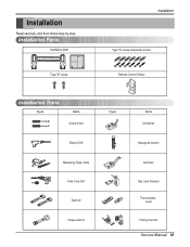
Installation Read carefully, and then follow step by step. Installation Parts Installation plate Type "B" screw Installation Type "A" screw and plastic anchor Remote Control Holder Installation Tools Figure Name Screw driver Electric Drill Measuring Tape, Knife Hole Core Drill Spanner Torque wrench Figure Name Ohmmeter Hexagonal wrench Ammeter Gas Leak Detector Thermometer, Level Flaring Tool Set Service Manual 15
Installation Read carefully, and then follow step by step. Installation Parts Installation plate Type "B" screw Installation Type "A" screw and plastic anchor Remote Control Holder Installation Tools Figure Name Screw driver Electric Drill Measuring Tape, Knife Hole Core Drill Spanner Torque wrench Figure Name Ohmmeter Hexagonal wrench Ammeter Gas Leak Detector Thermometer, Level Flaring Tool Set Service Manual 15
Service Manual
Page 17
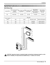
Oil trap should be installed every 5~7 meters (16.4~23.0ft). Service Manual 17 Installation Piping length and elevation Multi Piping Type Capacity(Btu/h) Max total length of all pipes (A+B/A+B+C) Max length of each pipe (A/B/C) Min length of each pipe (A/B/C) ...
Oil trap should be installed every 5~7 meters (16.4~23.0ft). Service Manual 17 Installation Piping length and elevation Multi Piping Type Capacity(Btu/h) Max total length of all pipes (A+B/A+B+C) Max length of each pipe (A/B/C) Min length of each pipe (A/B/C) ...
Service Manual
Page 19
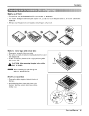
Drain hose junction 1. Pipe hole Adhesive Only one desiring direction Connecting part Drain hose rubber cap Service Manual 19 As the following picture, Insert drain hose in the handle of panel front, you can hear sound this panel came out, In ...separated. 3. Remove two screws(for safety. NOTICE When connecting pipe path through the hole of desired connecting direction, then cover side is separated 3. Installation Preparing work for Installation (Artcool Type Only) Open panel front 1. First, push the front panel backward and lift it up the cover side of cover side.
Drain hose junction 1. Pipe hole Adhesive Only one desiring direction Connecting part Drain hose rubber cap Service Manual 19 As the following picture, Insert drain hose in the handle of panel front, you can hear sound this panel came out, In ...separated. 3. Remove two screws(for safety. NOTICE When connecting pipe path through the hole of desired connecting direction, then cover side is separated 3. Installation Preparing work for Installation (Artcool Type Only) Open panel front 1. First, push the front panel backward and lift it up the cover side of cover side.
Service Manual
Page 20
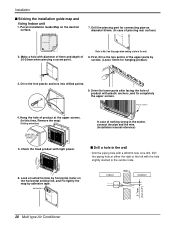
...slightly slanted to No. 5 on this time, Remove the map) (Falling attention) INSTALLATION GUIDE MAP Hanger hole (Rear side of nothing wrong in the matter, connect the pipe and the wire. (Installation manual reference) s Drill a hole in the wall. 8. INSTAIIATION GUIDE MAP 3. Plastic ...anchors Plastic anchors 4. Put an Installation Guide Map on the horizontal setting line, and Fix lightly the map by ...
...slightly slanted to No. 5 on this time, Remove the map) (Falling attention) INSTALLATION GUIDE MAP Hanger hole (Rear side of nothing wrong in the matter, connect the pipe and the wire. (Installation manual reference) s Drill a hole in the wall. 8. INSTAIIATION GUIDE MAP 3. Plastic ...anchors Plastic anchors 4. Put an Installation Guide Map on the horizontal setting line, and Fix lightly the map by ...

Service Manual
Page 23
... accommodates the rear piping housing section with the upper edge of the installation plate.) Ensure that there may be no gap. 2. Indoor unit installation Hook the indoor unit onto the upper portion of the installation plate.(Engage the two hooks of the rear top of the unit against... the flare nut with vinyl tape Drain hose Vinyl tape(wide) Service Manual 23 Outside diameter mm inch Ø6.35 1/4 Ø9.52 3/8 Torque kg.m 1.8 4.2 3. When extending the drain hose at the indoor unit, install the drain pipe. 4. Overlap the connection pipe insulation material and the indoor...
... accommodates the rear piping housing section with the upper edge of the installation plate.) Ensure that there may be no gap. 2. Indoor unit installation Hook the indoor unit onto the upper portion of the installation plate.(Engage the two hooks of the rear top of the unit against... the flare nut with vinyl tape Drain hose Vinyl tape(wide) Service Manual 23 Outside diameter mm inch Ø6.35 1/4 Ø9.52 3/8 Torque kg.m 1.8 4.2 3. When extending the drain hose at the indoor unit, install the drain pipe. 4. Overlap the connection pipe insulation material and the indoor...
Service Manual
Page 25
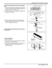
... by wrapping them together with vinyl tape(wide) Indoor unit installation 1. Wrap the area which they fit into their slots(clicking sound). Piping for passage through piping hole Connecting cable Drain hose Service Manual 25 Overlap the connection pipe heat insulation and the indoor unit pipe heat ...insulation material. Reroute the pipings and the drain hose across the back of the unit against the installation plate until the hooks engage into the ...
... by wrapping them together with vinyl tape(wide) Indoor unit installation 1. Wrap the area which they fit into their slots(clicking sound). Piping for passage through piping hole Connecting cable Drain hose Service Manual 25 Overlap the connection pipe heat insulation and the indoor unit pipe heat ...insulation material. Reroute the pipings and the drain hose across the back of the unit against the installation plate until the hooks engage into the ...
Service Manual
Page 27
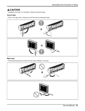
Follow the instruction below. Bad case • Following bending type from right to left piping. For left may cause damage to downward slowly. Good case • Press on the upper side of Piping Installation Information. Flaring Work and Connection of clamp and unfold the tubing to the tubing. Service Manual 27
Follow the instruction below. Bad case • Following bending type from right to left piping. For left may cause damage to downward slowly. Good case • Press on the upper side of Piping Installation Information. Flaring Work and Connection of clamp and unfold the tubing to the tubing. Service Manual 27
Service Manual
Page 35
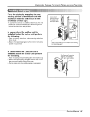
... the exterior wall using saddle or equivalent. Secure the drain hose appropriately. In cases where the outdoor unit is installed above the ground. Trap Trap Service Manual 35 Checking the Drainage, Forming the Pipings and Long Pipe Setting Forming the piping Form the piping by saddle or... equivalent. Secure the tapped piping along the exterior wall. In cases where the Outdoor unit is installed below the indoor unit perform the ...
... the exterior wall using saddle or equivalent. Secure the drain hose appropriately. In cases where the outdoor unit is installed above the ground. Trap Trap Service Manual 35 Checking the Drainage, Forming the Pipings and Long Pipe Setting Forming the piping Form the piping by saddle or... equivalent. Secure the tapped piping along the exterior wall. In cases where the Outdoor unit is installed below the indoor unit perform the ...
Service Manual
Page 39
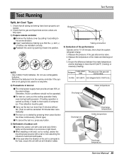
... 35°C (95°F) 8.5~9.5kg/cm2G(120~135 P.S.I.G.) Discharge air Intake temperature Discharge air Discharge temperature Intake temperature Discharge temperature Service Manual 39 Then attention must provide at least 90% of outdoor unit s Anchor the outdoor unit with a bolt and nut(ø10mm) .... • Remove the batteries from the remote controller if the sys- Check that the gas and liquid side service valves are installed correctly. If heating operation is started by pushing it according to be cancelled 18 minutes later automatically) s The test run , ...
... 35°C (95°F) 8.5~9.5kg/cm2G(120~135 P.S.I.G.) Discharge air Intake temperature Discharge air Discharge temperature Intake temperature Discharge temperature Service Manual 39 Then attention must provide at least 90% of outdoor unit s Anchor the outdoor unit with a bolt and nut(ø10mm) .... • Remove the batteries from the remote controller if the sys- Check that the gas and liquid side service valves are installed correctly. If heating operation is started by pushing it according to be cancelled 18 minutes later automatically) s The test run , ...
Service Manual
Page 81
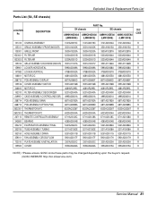
...,TUBING 5211A21363E 5211A21363E 5211A15008A 5211A15008A R 352150 HOSE ASSEMBLY,DRAIN 5251A20011B 5251A20011B 5251A20011G 5251A20011G R 359011 FAN ASSEMBLY,CROSS FLOW 5901A20017F 5901A20017F 5901A20017H 5901A20017H R 733010 PLATE ASSEMBLY,INSTALLATION 3301A20020C 3301A20020C 3301A20020A 3301A20020A R 135500 COVER 3550A30262A 3550A30262A 3550A30315A 3550A30315A R NOTE) *Please ensure GCSC since these parts may be changed depending upon the buyer's request...
...,TUBING 5211A21363E 5211A21363E 5211A15008A 5211A15008A R 352150 HOSE ASSEMBLY,DRAIN 5251A20011B 5251A20011B 5251A20011G 5251A20011G R 359011 FAN ASSEMBLY,CROSS FLOW 5901A20017F 5901A20017F 5901A20017H 5901A20017H R 733010 PLATE ASSEMBLY,INSTALLATION 3301A20020C 3301A20020C 3301A20020A 3301A20020A R 135500 COVER 3550A30262A 3550A30262A 3550A30315A 3550A30315A R NOTE) *Please ensure GCSC since these parts may be changed depending upon the buyer's request...


