

Service Manual
Page 2
... OF CONTENTS Model Number Nomenclature ...3 Symbols Used in this Manual ...4 Safety Precautions...5 Dimensions...11 Indoor Unit...11 Outdoor Unit ...12 Product Specifications ...13 Installation ...15 Installation Parts...15 Installation Tools...15 Select the best location ...16 Piping length and ...Refrigeration Cycle Diagram ...64 Self-diagnosis Function ...65 Cycle Troubleshooting Guide...66 Electronic Parts Troubleshooting Guide 67 General Information...72 2-way, 3-way Valve ...78 Exploded View & Replacement Parts List 82 Indoor Unit ...82 Outdoor Unit ...86 2 Multi type Air Conditioner
... OF CONTENTS Model Number Nomenclature ...3 Symbols Used in this Manual ...4 Safety Precautions...5 Dimensions...11 Indoor Unit...11 Outdoor Unit ...12 Product Specifications ...13 Installation ...15 Installation Parts...15 Installation Tools...15 Select the best location ...16 Piping length and ...Refrigeration Cycle Diagram ...64 Self-diagnosis Function ...65 Cycle Troubleshooting Guide...66 Electronic Parts Troubleshooting Guide 67 General Information...72 2-way, 3-way Valve ...78 Exploded View & Replacement Parts List 82 Indoor Unit ...82 Outdoor Unit ...86 2 Multi type Air Conditioner
Service Manual
Page 7
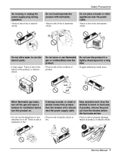
... not use the telephone or turn the product on or off or disconnect the power supply cable. Do not allow water to run into electric parts. • It may cause There is risk of property damage, failure of product. • Oxygen deficiency could occur. If possible, remove the product from product...
... not use the telephone or turn the product on or off or disconnect the power supply cable. Do not allow water to run into electric parts. • It may cause There is risk of property damage, failure of product. • Oxygen deficiency could occur. If possible, remove the product from product...
Service Manual
Page 9
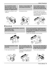
...; There is risk of fire, electric shock, or damage to clean. Do not use the product for your health. Wax Thinner Service Manual 9 Use a soft cloth to the plastic parts of the product. • There is risk of personal injury. They are very sharp! • It may cause product failure. • There....) • This could cause product malfunction or inefficient operation. Use two or more people to lift and transport the product. Do not touch the metal parts of air flow.
...; There is risk of fire, electric shock, or damage to clean. Do not use the product for your health. Wax Thinner Service Manual 9 Use a soft cloth to the plastic parts of the product. • There is risk of personal injury. They are very sharp! • It may cause product failure. • There....) • This could cause product malfunction or inefficient operation. Use two or more people to lift and transport the product. Do not touch the metal parts of air flow.
Service Manual
Page 13
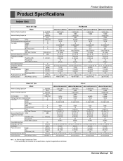
...of Rows & Column Dehumidification Rate Dimensions (W*H*D) Net Weight Piping Connection Liquid Gas Drain hose (ID Ø) Packing Dimension (W*H*D) Stuffing Quantity With(Without) S/Parts kcal/h(W) Btu/h kcal/h(W) Btu/h CMM(CFM) °C W V A EA/inch(mm) dBA inch(mm) l/h inch(mm) kg(lbs) ...Capacity 5 Model Nominal Heating Capacity 5 Air Circulation H/M/L Setting temperature range(cool/heat) Fan motor Output Model No. Service Manual 13 of innovation some specifications may be changed without notification. Due to our policy of Poles Input Running Current Fan Type ...
...of Rows & Column Dehumidification Rate Dimensions (W*H*D) Net Weight Piping Connection Liquid Gas Drain hose (ID Ø) Packing Dimension (W*H*D) Stuffing Quantity With(Without) S/Parts kcal/h(W) Btu/h kcal/h(W) Btu/h CMM(CFM) °C W V A EA/inch(mm) dBA inch(mm) l/h inch(mm) kg(lbs) ...Capacity 5 Model Nominal Heating Capacity 5 Air Circulation H/M/L Setting temperature range(cool/heat) Fan motor Output Model No. Service Manual 13 of innovation some specifications may be changed without notification. Due to our policy of Poles Input Running Current Fan Type ...
Service Manual
Page 15
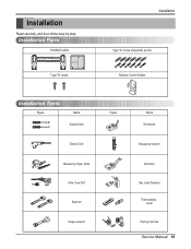
Installation Parts Installation plate Type "B" screw Installation Type "A" screw and plastic anchor Remote Control Holder Installation Tools Figure Name Screw driver Electric Drill Measuring Tape, Knife Hole Core Drill Spanner Torque wrench Figure Name Ohmmeter Hexagonal wrench Ammeter Gas Leak Detector Thermometer, Level Flaring Tool Set Service Manual 15 Installation Read carefully, and then follow step by step.
Installation Parts Installation plate Type "B" screw Installation Type "A" screw and plastic anchor Remote Control Holder Installation Tools Figure Name Screw driver Electric Drill Measuring Tape, Knife Hole Core Drill Spanner Torque wrench Figure Name Ohmmeter Hexagonal wrench Ammeter Gas Leak Detector Thermometer, Level Flaring Tool Set Service Manual 15 Installation Read carefully, and then follow step by step.
Service Manual
Page 19
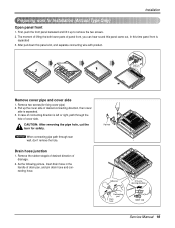
...Remove the rubber stopple of desired direction of drain pan, and join drain hose and connecting hose. The moment of lifting the both lower parts of cover side. Pull up to remove the two screws. 2. Drain hose junction 1. As the following picture, Insert drain hose in... the handle of drainage. 2. Pipe hole Adhesive Only one desiring direction Connecting part Drain hose rubber cap Service Manual 19 In case of desired connecting direction, then cover side is separated 3. Installation Preparing work for fixing cover pipe) 2. Remove...
...Remove the rubber stopple of desired direction of drain pan, and join drain hose and connecting hose. The moment of lifting the both lower parts of cover side. Pull up to remove the two screws. 2. Drain hose junction 1. As the following picture, Insert drain hose in... the handle of drainage. 2. Pipe hole Adhesive Only one desiring direction Connecting part Drain hose rubber cap Service Manual 19 In case of desired connecting direction, then cover side is separated 3. Installation Preparing work for fixing cover pipe) 2. Remove...
Service Manual
Page 20
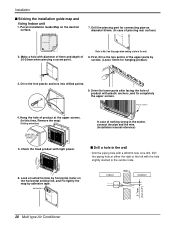
... by screws. (Leave 10mm for connecting pipe as diameter 50mm. (In case of nothing wrong in the matter, connect the pipe and the wire. (Installation manual reference) s Drill a hole in the wall. 8. Look at the upper screws. (In this page when making a hole in the wall • Drill the .... Put an Installation Guide Map on this time, Remove the map) (Falling attention) INSTALLATION GUIDE MAP Hanger hole (Rear side of the upper parts by adhesive tape. Drive the fore plastic anchors into drilled points. Drill the piping hole at either the right or the left with diameter of...
... by screws. (Leave 10mm for connecting pipe as diameter 50mm. (In case of nothing wrong in the matter, connect the pipe and the wire. (Installation manual reference) s Drill a hole in the wall. 8. Look at the upper screws. (In this page when making a hole in the wall • Drill the .... Put an Installation Guide Map on this time, Remove the map) (Falling attention) INSTALLATION GUIDE MAP Hanger hole (Rear side of the upper parts by adhesive tape. Drive the fore plastic anchors into drilled points. Drill the piping hole at either the right or the left with diameter of...
Service Manual
Page 31
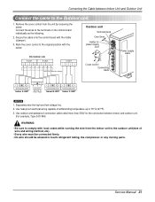
... to 75°C(167°F). 3. Connecting cable(Low voltage) Connect the wires to the original position with the holder (clamper). 3. Service Manual 31 Outdoor unit Terminal block Over 5mm Holder for the connection between Indoor Unit and Outdoor Unit Connect the cable to the Outdoor unit. 1.... • Every wire must be connected firmly. • No wire should be allowed to touch refrigerant tubing, the compressor or any moving parts. Use outdoor and waterproof connection cable rated more than 300V for power supply cord 36k Outdoor side A-UNIT 1234 B-UNIT 1234 C-UNIT 1234 ...
... to 75°C(167°F). 3. Connecting cable(Low voltage) Connect the wires to the original position with the holder (clamper). 3. Service Manual 31 Outdoor unit Terminal block Over 5mm Holder for the connection between Indoor Unit and Outdoor Unit Connect the cable to the Outdoor unit. 1.... • Every wire must be connected firmly. • No wire should be allowed to touch refrigerant tubing, the compressor or any moving parts. Use outdoor and waterproof connection cable rated more than 300V for power supply cord 36k Outdoor side A-UNIT 1234 B-UNIT 1234 C-UNIT 1234 ...
Service Manual
Page 35
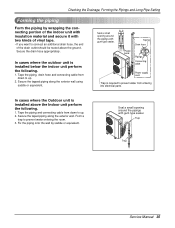
...Power supply cord • Trap is required to prevent water entering the room. 3. Form a trap to prevent water from entering into electrical parts. Tape the piping, drain hose and connecting cable from down to up . 2. Fix the piping onto the wall by wrapping the connecting ... small opening around the pipings with gum type sealer. Tape the piping and connecting cable from down to up . 2. Trap Trap Service Manual 35 In cases where the outdoor unit is installed above the ground. Secure the drain hose appropriately. Checking the Drainage, Forming the Pipings and...
...Power supply cord • Trap is required to prevent water entering the room. 3. Form a trap to prevent water from entering into electrical parts. Tape the piping, drain hose and connecting cable from down to up . 2. Fix the piping onto the wall by wrapping the connecting ... small opening around the pipings with gum type sealer. Tape the piping and connecting cable from down to up . 2. Trap Trap Service Manual 35 In cases where the outdoor unit is installed above the ground. Secure the drain hose appropriately. Checking the Drainage, Forming the Pipings and...
Service Manual
Page 67
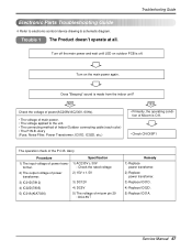
...is off the main power and wait until LED on the main power again. tion of Micom is made from the indoor unit? Service Manual 67 NO Check the voltage of power(AC208V/AC230V, 60Hz). • The voltage of main power. • The voltage applied to electronic...4) IC02D(7805) 5) IC01A(KIA7036) Specification 1) AC230V ± 30V : Check the rated voltage 2) 15V ± 1.5V 3) DC12V 4) DC5V 5) The voltage of power trans- Electronic Parts Troubleshooting Guide ❇ Refer to the unit. • The connecting method of Indoor/Outdoor connecting cable (each color) • The P.W.B.
...is off the main power and wait until LED on the main power again. tion of Micom is made from the indoor unit? Service Manual 67 NO Check the voltage of power(AC208V/AC230V, 60Hz). • The voltage of main power. • The voltage applied to electronic...4) IC02D(7805) 5) IC01A(KIA7036) Specification 1) AC230V ± 30V : Check the rated voltage 2) 15V ± 1.5V 3) DC12V 4) DC5V 5) The voltage of power trans- Electronic Parts Troubleshooting Guide ❇ Refer to the unit. • The connecting method of Indoor/Outdoor connecting cable (each color) • The P.W.B.
Service Manual
Page 71
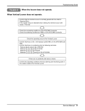
... there are no problems after above checks • Confirm the assembly conditions that are catching and interfering parts in the rotation radial of IC01M - Between 12 , 13 , 14 , 15 of the Vertical Louver Service Manual 71 When Vertical Louver does not operate. • Confirm that the Vertical Louver is normally geared with...
... there are no problems after above checks • Confirm the assembly conditions that are catching and interfering parts in the rotation radial of IC01M - Between 12 , 13 , 14 , 15 of the Vertical Louver Service Manual 71 When Vertical Louver does not operate. • Confirm that the Vertical Louver is normally geared with...
Service Manual
Page 81
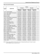
... 5901A20017H R 733010 PLATE ASSEMBLY,INSTALLATION 3301A20020C 3301A20020C 3301A20020A 3301A20020A R 135500 COVER 3550A30262A 3550A30262A 3550A30315A 3550A30315A R NOTE) *Please ensure GCSC since these parts may be changed depending upon the buyer's request. (GCSC WEBSITE http://biz.LGservice.com) Service Manual 81 Parts List (S4, SE chassis) Exploded View & Replacement Parts List LOCATION No. DESCRIPTION S4 chassis...
... 5901A20017H R 733010 PLATE ASSEMBLY,INSTALLATION 3301A20020C 3301A20020C 3301A20020A 3301A20020A R 135500 COVER 3550A30262A 3550A30262A 3550A30315A 3550A30315A R NOTE) *Please ensure GCSC since these parts may be changed depending upon the buyer's request. (GCSC WEBSITE http://biz.LGservice.com) Service Manual 81 Parts List (S4, SE chassis) Exploded View & Replacement Parts List LOCATION No. DESCRIPTION S4 chassis...
Service Manual
Page 83
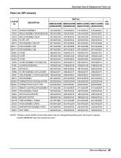
... 5251AR1222R 5251AR1222R R 354210 EVAPORATOR ASSEMBLY,FIRST 5421A20072A 5421A20072A 5421A20072A 5421A20072A R 359012 FAN,TURBO 5900A00003A 5900A00003A 5900A00003A 5900A00003A R NOTE) *Please ensure GCSC since these parts may be changed depending upon the buyer's request. (GCSC WEBSITE http://biz.LGservice.com) Service Manual 83 DESCRIPTION PART No. Exploded View & Replacement Parts List Parts List (SP3 chassis) LOCATION No.
... 5251AR1222R 5251AR1222R R 354210 EVAPORATOR ASSEMBLY,FIRST 5421A20072A 5421A20072A 5421A20072A 5421A20072A R 359012 FAN,TURBO 5900A00003A 5900A00003A 5900A00003A 5900A00003A R NOTE) *Please ensure GCSC since these parts may be changed depending upon the buyer's request. (GCSC WEBSITE http://biz.LGservice.com) Service Manual 83 DESCRIPTION PART No. Exploded View & Replacement Parts List Parts List (SP3 chassis) LOCATION No.
Service Manual
Page 85
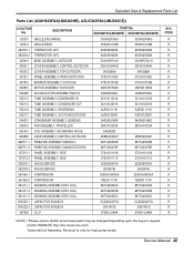
...ASSEMBLY(EEV COIL) DRAWING,ASSEMBLY(EEV COIL) CAPACITOR,FILM,BOX CAPACITOR,FILM,BOX O.L.P PART No. A3UH363FA0(LMU360HE) A3UC363FA0(LMU360CE) 3530A20006G 3530A20006G 3530A10176B 3530A10176B 6323A20028A 6323A20028A 6323A20026A 6323A20026A 3041AP2741H 3041AP2741H 3551A10044G 3551A10044H 3H03266H 3H03266H ...R R R R R R R R R R R R R R R R R R R R R R R R R R R R R R R R R NOTE) *Please ensure GCSC since these parts may be changed depending upon the buyer's request. (GCSC WEBSITE http://biz.LGservice.com) Solenoid(Coil Assembly, Reverse) is only for heat pump model. Service...
...ASSEMBLY(EEV COIL) DRAWING,ASSEMBLY(EEV COIL) CAPACITOR,FILM,BOX CAPACITOR,FILM,BOX O.L.P PART No. A3UH363FA0(LMU360HE) A3UC363FA0(LMU360CE) 3530A20006G 3530A20006G 3530A10176B 3530A10176B 6323A20028A 6323A20028A 6323A20026A 6323A20026A 3041AP2741H 3041AP2741H 3551A10044G 3551A10044H 3H03266H 3H03266H ...R R R R R R R R R R R R R R R R R R R R R R R R R R R R R R R R R NOTE) *Please ensure GCSC since these parts may be changed depending upon the buyer's request. (GCSC WEBSITE http://biz.LGservice.com) Solenoid(Coil Assembly, Reverse) is only for heat pump model. Service...


