
Service Manual
Page 2
... Checking method ...36 Evacuation...37 Charging ...38 Test Running ...39 Operation ...40 Function of control...40 Function of Indoor Unit ...45 Function of Outdoor Unit ...47 Remote Control Operation ...48 Disassembly ...49 Indoor Unit...49 Schematic Diagram...54 Electronic Control Device ...54 Wiring Diagram...58 Components Locations...59 Troubleshooting Guide ...64 Refrigeration Cycle Diagram...
... Checking method ...36 Evacuation...37 Charging ...38 Test Running ...39 Operation ...40 Function of control...40 Function of Indoor Unit ...45 Function of Outdoor Unit ...47 Remote Control Operation ...48 Disassembly ...49 Indoor Unit...49 Schematic Diagram...54 Electronic Control Device ...54 Wiring Diagram...58 Components Locations...59 Troubleshooting Guide ...64 Refrigeration Cycle Diagram...
Service Manual
Page 10
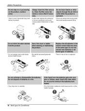
... air conditioner and could cause product malfunction or damage. • There are sharp and moving parts that could cause personal injury. Do not use the remote if the batteries have leaked. • The chemicals in a fire. • They may burn or explode. injury. Do not insert hands or other objects through... and avoid personal serious health issues. If the liquid from the product. Do not dispose of the same type. Replace the all batteries in the remote control with clean water. Clean the filter every two weeks or more often if necessary.
... air conditioner and could cause product malfunction or damage. • There are sharp and moving parts that could cause personal injury. Do not use the remote if the batteries have leaked. • The chemicals in a fire. • They may burn or explode. injury. Do not insert hands or other objects through... and avoid personal serious health issues. If the liquid from the product. Do not dispose of the same type. Replace the all batteries in the remote control with clean water. Clean the filter every two weeks or more often if necessary.
Service Manual
Page 15
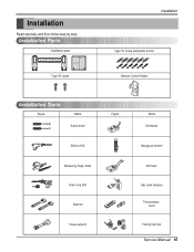
Installation Parts Installation plate Type "B" screw Installation Type "A" screw and plastic anchor Remote Control Holder Installation Tools Figure Name Screw driver Electric Drill Measuring Tape, Knife Hole Core Drill Spanner Torque wrench Figure Name Ohmmeter Hexagonal wrench Ammeter Gas Leak Detector Thermometer, Level Flaring Tool Set Service Manual 15 Installation Read carefully, and then follow step by step.
Installation Parts Installation plate Type "B" screw Installation Type "A" screw and plastic anchor Remote Control Holder Installation Tools Figure Name Screw driver Electric Drill Measuring Tape, Knife Hole Core Drill Spanner Torque wrench Figure Name Ohmmeter Hexagonal wrench Ammeter Gas Leak Detector Thermometer, Level Flaring Tool Set Service Manual 15 Installation Read carefully, and then follow step by step.
Service Manual
Page 28
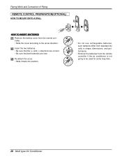
...(OPTIONAL) HOW TO MOUNT ONTO A WALL HOW TO INSERT BATTERIES Remove the battery cover from the remote controller if the air conditioner is not going to the arrow direction. Re-attach the cover. • Slide it back into position. • Do not use ...rechargeable batteries, such batteries differ from standard dry cells in shape, dimensions, and performance. • Romove the batteries from the remote controller. • Slide the cover according to be used for some long time. 28 Multi type Air Conditioner Insert the two batteries. • Be sure that...
...(OPTIONAL) HOW TO MOUNT ONTO A WALL HOW TO INSERT BATTERIES Remove the battery cover from the remote controller if the air conditioner is not going to the arrow direction. Re-attach the cover. • Slide it back into position. • Do not use ...rechargeable batteries, such batteries differ from standard dry cells in shape, dimensions, and performance. • Romove the batteries from the remote controller. • Slide the cover according to be used for some long time. 28 Multi type Air Conditioner Insert the two batteries. • Be sure that...
Service Manual
Page 39
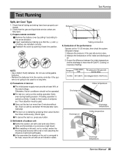
... run , carry out the cooling operation firstly even during heating season. Do not use rechargeable batteries. • Remove the batteries from the remote controller if the sys- s For test run is started by pushing it according to the arrow direction. s When installing on the wall, roof... tightly and horizontally on a concrete or rigid mount. If heating operation is conveyed to the trouble of battery are fully open. 1) Prepare remote controller Remove the battery cover by pulling it back into position. Test Running Test Running Split, Art Cool Type 1. Check that the (+) and ...
... run , carry out the cooling operation firstly even during heating season. Do not use rechargeable batteries. • Remove the batteries from the remote controller if the sys- s For test run is started by pushing it according to the arrow direction. s When installing on the wall, roof... tightly and horizontally on a concrete or rigid mount. If heating operation is conveyed to the trouble of battery are fully open. 1) Prepare remote controller Remove the battery cover by pulling it back into position. Test Running Test Running Split, Art Cool Type 1. Check that the (+) and ...

Service Manual
Page 40
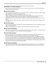
...above the setting temp, they start during heating mode operation or while in compressor running, operating with the airflow speed set by the remote control is received, the intake air temperature is detected and the setting temp is completed or canceled Defrost Indicator • Off except when...176;C(75.2°F) ≤ Intake Intake Air Temp s Soft Dry Operation Mode • When the dehumidification operation input by the remote control. While compressor is off when timer mode is automatically set according to operate again. Operation Operation Function of the setting.
...above the setting temp, they start during heating mode operation or while in compressor running, operating with the airflow speed set by the remote control is received, the intake air temperature is detected and the setting temp is completed or canceled Defrost Indicator • Off except when...176;C(75.2°F) ≤ Intake Intake Air Temp s Soft Dry Operation Mode • When the dehumidification operation input by the remote control. While compressor is off when timer mode is automatically set according to operate again. Operation Operation Function of the setting.

Service Manual
Page 42
Compressor ON Temp ➲ Setting Temp + 0.5°C(32.9°F) Compressor OFF Temp ➲ Setting Temp+0.5°C(32.9°F) • At the beginning of Fuzzy mode operation, the setting temperature is automatically selected according to the setting temperature selected by Fuzzy rule, when the intake air temp is 0.5°C(32.9°F) or more above the setting temp, the compressor is turned off. Operation 2) Fuzzy Operation for Dehumidification • According to the intake air temp at that time. 26°C(78.8°F) ≤ Intake Air Temp ➲ 25°C(77...
Compressor ON Temp ➲ Setting Temp + 0.5°C(32.9°F) Compressor OFF Temp ➲ Setting Temp+0.5°C(32.9°F) • At the beginning of Fuzzy mode operation, the setting temperature is automatically selected according to the setting temperature selected by Fuzzy rule, when the intake air temp is 0.5°C(32.9°F) or more above the setting temp, the compressor is turned off. Operation 2) Fuzzy Operation for Dehumidification • According to the intake air temp at that time. 26°C(78.8°F) ≤ Intake Air Temp ➲ 25°C(77...
Service Manual
Page 43
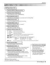
...kept on the memory. s Off-Timer On-Timer Operation • When the set time is reached after the on/off time is input by the remote control, the on/off-timer operation is on pause at the time set by the Chaos Simulation. s Sleep Timer Operation • When the sleep time ... be input. • While in cooling mode operation, 30 min later since the start of the sleep timer, the setting temperature increases by the remote control while in appliance operation, the operation of the initial cooling mode and then operated in the mode on the memory and the appliance automatically operates...
...kept on the memory. s Off-Timer On-Timer Operation • When the set time is reached after the on/off time is input by the remote control, the on/off-timer operation is on pause at the time set by the Chaos Simulation. s Sleep Timer Operation • When the sleep time ... be input. • While in cooling mode operation, 30 min later since the start of the sleep timer, the setting temperature increases by the remote control while in appliance operation, the operation of the initial cooling mode and then operated in the mode on the memory and the appliance automatically operates...

Service Manual
Page 44
...176;F), High Speed 21°C(69.8°F)≤Intake Air Temp tion condition is set according to the Auto Restarting position or the remote control position, the forced operation is canceled and the appliance stops operating. • In the forced operation mode, the indoor fan is switched from... the remote control position to the forced operation position while the power is on, the forced operation is carried out. • When the slide switch position...
...176;F), High Speed 21°C(69.8°F)≤Intake Air Temp tion condition is set according to the Auto Restarting position or the remote control position, the forced operation is canceled and the appliance stops operating. • In the forced operation mode, the indoor fan is switched from... the remote control position to the forced operation position while the power is on, the forced operation is carried out. • When the slide switch position...
Service Manual
Page 45
... Mode Auto operation. Timer : Lights up during the system operation. Natural Air Control by Remote controller Sensing the Room Temperature • Room temperature sensor. (THERMISTOR) Room temperature control • Maintains the room temperature in accordance with the Setting Temp. Indoor Fan Speed Control • High, Med, Low, Chaos, Jet Cool Operation indication Lamps (LED) On...
... Mode Auto operation. Timer : Lights up during the system operation. Natural Air Control by Remote controller Sensing the Room Temperature • Room temperature sensor. (THERMISTOR) Room temperature control • Maintains the room temperature in accordance with the Setting Temp. Indoor Fan Speed Control • High, Med, Low, Chaos, Jet Cool Operation indication Lamps (LED) On...

Service Manual
Page 46
...) : Lights up and down automatically. Soft Dry Operation Mode • Intermittent operation of fan at the starting. Natural Air Control by Remote controller Sensing the Room Temperature • Room temperature sensor. (THERMISTOR) Room temperature control • Maintains the room temperature in any operation mode with selecting the function. • The function is to be...
...) : Lights up and down automatically. Soft Dry Operation Mode • Intermittent operation of fan at the starting. Natural Air Control by Remote controller Sensing the Room Temperature • Room temperature sensor. (THERMISTOR) Room temperature control • Maintains the room temperature in any operation mode with selecting the function. • The function is to be...
Service Manual
Page 48
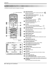
...to check the room temperature. 13 PLASMA(OPTIONAL) Used to start or stop the plasma-purification function. 14 RESET BUTTON Initialize remote controller. 15 2nd F Button Used prior to using modes printed in blue at the bottom of buttons. 16 AUTO CLEAN Used...730;F SWITCHING BUTTON Used to switch temperature reading from Centigrade to Fahrenheit. 18 HORIZONTAL AIRFLOW DIRECTION CONTROL BUTTON (NOT ON ALL MODELS) Used to the system. Operation Remote Control Operation The Remote Controller transmits the signals to set the desired horizontal airflow direction. 48 Multi type Air Conditioner
...to check the room temperature. 13 PLASMA(OPTIONAL) Used to start or stop the plasma-purification function. 14 RESET BUTTON Initialize remote controller. 15 2nd F Button Used prior to using modes printed in blue at the bottom of buttons. 16 AUTO CLEAN Used...730;F SWITCHING BUTTON Used to switch temperature reading from Centigrade to Fahrenheit. 18 HORIZONTAL AIRFLOW DIRECTION CONTROL BUTTON (NOT ON ALL MODELS) Used to the system. Operation Remote Control Operation The Remote Controller transmits the signals to set the desired horizontal airflow direction. 48 Multi type Air Conditioner

Service Manual
Page 68
... and wind speed selecting. Caused by a low speed. When the compressor stopped Indoor Fan is driven by other parts except the remote controller When the mark ( ) is displayed in the Sleeping Mode, the wind speed is impossible to the low speed as force.) Caused by the... the Display PWB Ass'y • Check receiver ass'y 68 Multi type Air Conditioner Troubleshooting Guide Trouble 2 Product doesn't operate with the remote controller. Turn on main power. While the compressor has been stopped, the compressor does not operate owing to the delaying function for 3 minutes after ...
... and wind speed selecting. Caused by a low speed. When the compressor stopped Indoor Fan is driven by other parts except the remote controller When the mark ( ) is displayed in the Sleeping Mode, the wind speed is impossible to the low speed as force.) Caused by the... the Display PWB Ass'y • Check receiver ass'y 68 Multi type Air Conditioner Troubleshooting Guide Trouble 2 Product doesn't operate with the remote controller. Turn on main power. While the compressor has been stopped, the compressor does not operate owing to the delaying function for 3 minutes after ...
Service Manual
Page 69
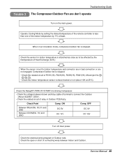
... connection or are don't operate Turn on the main power. When in Outdoor PCB Ass'y. Operate Cooling Mode by setting the disired temperature of the remote controller is less than one of the Indoor temperature by the themperature of Heat Exchange (EVA.) When the sensor circuit for Indoor temperature is attatched as...
... connection or are don't operate Turn on the main power. When in Outdoor PCB Ass'y. Operate Cooling Mode by setting the disired temperature of the remote controller is less than one of the Indoor temperature by the themperature of Heat Exchange (EVA.) When the sensor circuit for Indoor temperature is attatched as...
Service Manual
Page 81
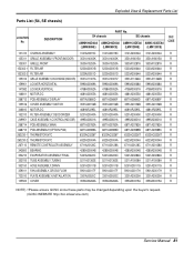
... 6871A20782A R 668713 PCB ASSEMBLY(OPTION PCB) 6871A20989A 6871A20989D 6871A20989B 6871A20989C R 263230-1 THERMISTOR,NTC 6323AQ3226T 6323AQ3226T 6323AQ3226T 6323AQ3226T R 263230-2 THERMISTOR,NTC 6323A20004A 6323A20004A 6323A20004A 6323A20004A R 267110 REMOTE CONTROLLER ASSEMBLY 6711A20128C 6711A20128A 6711A20128C 6711A20128A R 342800 BEARING 4280A20004B 4280A20004B 4280A20004B 4280A20004B R 354210 EVAPORATOR ASSEMBLY,FINAL 5421A20222C 5421A20222C 5421A20282A 5421A20282A R 35211B TUBE ASSEMBLY,TUBING 5211A21363E 5211A21363E...
... 6871A20782A R 668713 PCB ASSEMBLY(OPTION PCB) 6871A20989A 6871A20989D 6871A20989B 6871A20989C R 263230-1 THERMISTOR,NTC 6323AQ3226T 6323AQ3226T 6323AQ3226T 6323AQ3226T R 263230-2 THERMISTOR,NTC 6323A20004A 6323A20004A 6323A20004A 6323A20004A R 267110 REMOTE CONTROLLER ASSEMBLY 6711A20128C 6711A20128A 6711A20128C 6711A20128A R 342800 BEARING 4280A20004B 4280A20004B 4280A20004B 4280A20004B R 354210 EVAPORATOR ASSEMBLY,FINAL 5421A20222C 5421A20222C 5421A20282A 5421A20282A R 35211B TUBE ASSEMBLY,TUBING 5211A21363E 5211A21363E...
Service Manual
Page 83
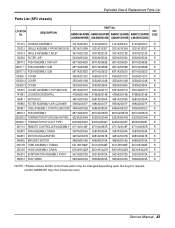
... ASSEMBLY 6871A20387K 6871A20387M 6871A20387M 6871A20387N R 263230-2 THERMISTOR,NTC(ROOM+IN PIPE) 6323A20004N 6323A20004N 6323A20004N 6323A20004N R 263230-1 THERMISTOR,NTC(OUT PIPE) 6323AQ3226T 6323AQ3226T 6323AQ3226T 6323AQ3226T R 267110 REMOTE CONTROLLER ASSEMBLY 6711A20128F 6711A20083R 6711A20128F 6711A20083R R 330870 PAN ASSEMBLY,DRAIN 3087A30004A 3087A30004A 3087A30004A 3087A30004A R 346810 MOTOR,UNCLASSIFIED 4681A20047B 4681A20047B 4681A20047B 4681A20047B R 349600 BRACKET,MOTOR 4960A20016A 4960A20016A...
... ASSEMBLY 6871A20387K 6871A20387M 6871A20387M 6871A20387N R 263230-2 THERMISTOR,NTC(ROOM+IN PIPE) 6323A20004N 6323A20004N 6323A20004N 6323A20004N R 263230-1 THERMISTOR,NTC(OUT PIPE) 6323AQ3226T 6323AQ3226T 6323AQ3226T 6323AQ3226T R 267110 REMOTE CONTROLLER ASSEMBLY 6711A20128F 6711A20083R 6711A20128F 6711A20083R R 330870 PAN ASSEMBLY,DRAIN 3087A30004A 3087A30004A 3087A30004A 3087A30004A R 346810 MOTOR,UNCLASSIFIED 4681A20047B 4681A20047B 4681A20047B 4681A20047B R 349600 BRACKET,MOTOR 4960A20016A 4960A20016A...


