
Service Manual
Page 1
website http://www.lgservice.com LG Multi Type Air Conditioner SERVICE MANUAL MODEL • Indoor Unit: Room Type AMNH093D4A0(LMN090HE) AMNC093D4A0(LMN090CE) AMNH123DEA0(LMN120HE) AMNC123DEA0(LMN120CE) Art Cool Type AMNH093APM0(LMAN090HNS) AMNC093APM0(LMAN090CNS) AMNH123APM0(LMAN120HNS) AMNC123APM0(LMAN120CNS) • Outdoor Unit: A3UH363FA0(LMU360HE) A3UC363FA0(LMU360CE) LG CAUTION • BEFORE SERVICING THE UNIT, READ THE SAFETY PRECAUTIONS IN THIS MANUAL. • ONLY FOR AUTHORIZED SERVICE PERSONNEL.
website http://www.lgservice.com LG Multi Type Air Conditioner SERVICE MANUAL MODEL • Indoor Unit: Room Type AMNH093D4A0(LMN090HE) AMNC093D4A0(LMN090CE) AMNH123DEA0(LMN120HE) AMNC123DEA0(LMN120CE) Art Cool Type AMNH093APM0(LMAN090HNS) AMNC093APM0(LMAN090CNS) AMNH123APM0(LMAN120HNS) AMNC123APM0(LMAN120CNS) • Outdoor Unit: A3UH363FA0(LMU360HE) A3UC363FA0(LMU360CE) LG CAUTION • BEFORE SERVICING THE UNIT, READ THE SAFETY PRECAUTIONS IN THIS MANUAL. • ONLY FOR AUTHORIZED SERVICE PERSONNEL.

Service Manual
Page 2
... OF CONTENTS Model Number Nomenclature ...3 Symbols Used in this Manual ...4 Safety Precautions...5 Dimensions...11 Indoor Unit...11 Outdoor Unit ...12 Product Specifications ...13 Installation ...15 Installation Parts...15 Installation Tools...15 Select the best location ......
... OF CONTENTS Model Number Nomenclature ...3 Symbols Used in this Manual ...4 Safety Precautions...5 Dimensions...11 Indoor Unit...11 Outdoor Unit ...12 Product Specifications ...13 Installation ...15 Installation Parts...15 Installation Tools...15 Select the best location ......
Service Manual
Page 3
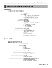
look type N : N- of Connectable Indoor Units Ex) A3U : Connectable max. 2 Indoor Units Service Manual 3 Model Number Nomenclature Model Number Nomenclature Indoor Unit AMN H 09 3 D 4 A 0 Serial Number Function A : Basic, L : Nano Plasma + Auto Clean(Wall Mounted) C: Plasma(Ceiling Cassette), G: Low Static ...
look type N : N- of Connectable Indoor Units Ex) A3U : Connectable max. 2 Indoor Units Service Manual 3 Model Number Nomenclature Model Number Nomenclature Indoor Unit AMN H 09 3 D 4 A 0 Serial Number Function A : Basic, L : Nano Plasma + Auto Clean(Wall Mounted) C: Plasma(Ceiling Cassette), G: Low Static ...
Service Manual
Page 4
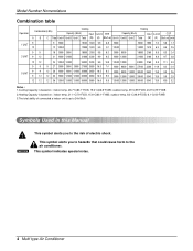
... temp. 8.3°C(46.9°F)DB, 6.1°C(43°F)WB 3.The total ability of connected a indoor unit is up to 24k Btu/h Symbols Used in this Manual This symbol alerts you to hazards that could cause harm to the risk of electric shock. outdoor temp. 35°C(95°F)DB, 23.9°...
... temp. 8.3°C(46.9°F)DB, 6.1°C(43°F)WB 3.The total ability of connected a indoor unit is up to 24k Btu/h Symbols Used in this Manual This symbol alerts you to hazards that could cause harm to the risk of electric shock. outdoor temp. 35°C(95°F)DB, 23.9°...
Service Manual
Page 5
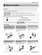
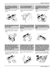
... to properties only. WARNING This symbol indicates the possibility of fire or electric cause fire or electric shock shock. cuit and breaker. Service Manual 5 Install the panel and the cover Always install a dedicated cir- s Meanings of fire or electric shock. rated circuit breaker. There ... The seriousness is risk of symbols used in this dealer, seller, a qualified electrician, appliance on a dedicated circuit. Use this manual are as shown below. Use the correctly rated break- Be sure not to do. WARNING s Installation Do not use a defective or under-
... to properties only. WARNING This symbol indicates the possibility of fire or electric cause fire or electric shock shock. cuit and breaker. Service Manual 5 Install the panel and the cover Always install a dedicated cir- s Meanings of fire or electric shock. rated circuit breaker. There ... The seriousness is risk of symbols used in this dealer, seller, a qualified electrician, appliance on a dedicated circuit. Use this manual are as shown below. Use the correctly rated break- Be sure not to do. WARNING s Installation Do not use a defective or under-
Service Manual
Page 7
... of fire, failure of the product, or electric shock. Do not store or use flammable Do not use the product in storm or hurricane. Service Manual 7 Do not allow water to run into electric parts. • It may cause There is risk of product, or electric shock. Turn the breaker off...
... of fire, failure of the product, or electric shock. Do not store or use flammable Do not use the product in storm or hurricane. Service Manual 7 Do not allow water to run into electric parts. • It may cause There is risk of product, or electric shock. Turn the breaker off...
Service Manual
Page 9
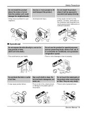
... injury. Use two or more people to clean. Use a soft cloth to lift and transport the product. Corrosion, particularly on the product. Wax Thinner Service Manual 9
... injury. Use two or more people to clean. Use a soft cloth to lift and transport the product. Corrosion, particularly on the product. Wax Thinner Service Manual 9

Service Manual
Page 11
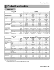
Dimensions Indoor Unit 1. Split Type Indoor H D W Dimensions 2. Art Cool Type Indoor Unit W D H Pipe Hole Hanger Hole Installation plate Fix Hole Dimension W H D Model mm mm mm Split Type S4 SE 9 kBtu/h 12 kBtu/h 840 895 270 282 153 165 ARTCOOL Type SP3 9 kBtu/h 12 kBtu/h 570 568 129 Service Manual 11
Dimensions Indoor Unit 1. Split Type Indoor H D W Dimensions 2. Art Cool Type Indoor Unit W D H Pipe Hole Hanger Hole Installation plate Fix Hole Dimension W H D Model mm mm mm Split Type S4 SE 9 kBtu/h 12 kBtu/h 840 895 270 282 153 165 ARTCOOL Type SP3 9 kBtu/h 12 kBtu/h 570 568 129 Service Manual 11
Service Manual
Page 13
.../719 (792) Indoor Unit Type Nominal Cooling Capacity 5 Model Nominal Heating Capacity 5 Air Circulation H/M/L Setting temperature range(cool/heat) Fan motor Output Model No. Service Manual 13 Product Specifications Product Specifications Indoor Unit Indoor Unit Type Nominal Cooling Capacity 5 Model Nominal Heating Capacity 5 Air Circulation H/M/L Setting temperature range(cool/heat) Fan...
.../719 (792) Indoor Unit Type Nominal Cooling Capacity 5 Model Nominal Heating Capacity 5 Air Circulation H/M/L Setting temperature range(cool/heat) Fan motor Output Model No. Service Manual 13 Product Specifications Product Specifications Indoor Unit Indoor Unit Type Nominal Cooling Capacity 5 Model Nominal Heating Capacity 5 Air Circulation H/M/L Setting temperature range(cool/heat) Fan...
Service Manual
Page 15
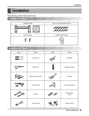
Installation Read carefully, and then follow step by step. Installation Parts Installation plate Type "B" screw Installation Type "A" screw and plastic anchor Remote Control Holder Installation Tools Figure Name Screw driver Electric Drill Measuring Tape, Knife Hole Core Drill Spanner Torque wrench Figure Name Ohmmeter Hexagonal wrench Ammeter Gas Leak Detector Thermometer, Level Flaring Tool Set Service Manual 15
Installation Read carefully, and then follow step by step. Installation Parts Installation plate Type "B" screw Installation Type "A" screw and plastic anchor Remote Control Holder Installation Tools Figure Name Screw driver Electric Drill Measuring Tape, Knife Hole Core Drill Spanner Torque wrench Figure Name Ohmmeter Hexagonal wrench Ammeter Gas Leak Detector Thermometer, Level Flaring Tool Set Service Manual 15
Service Manual
Page 17
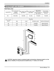
Oil trap should be installed every 5~7 meters (16.4~23.0ft). Service Manual 17 Installation Piping length and elevation Multi Piping Type Capacity(Btu/h) Max total length of all pipes (A+B/A+B+C) Max length of each pipe (A/B/C) Min length of ...
Oil trap should be installed every 5~7 meters (16.4~23.0ft). Service Manual 17 Installation Piping length and elevation Multi Piping Type Capacity(Btu/h) Max total length of all pipes (A+B/A+B+C) Max length of each pipe (A/B/C) Min length of ...
Service Manual
Page 19
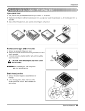
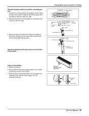
... removing the pipe hole, cut the burr for fixing cover pipe) 2. Pipe hole Adhesive Only one desiring direction Connecting part Drain hose rubber cap Service Manual 19 Remove two screws(for safety. Remove the rubber stopple of desired direction of drain pan, and join drain hose and connecting hose. As the...
... removing the pipe hole, cut the burr for fixing cover pipe) 2. Pipe hole Adhesive Only one desiring direction Connecting part Drain hose rubber cap Service Manual 19 Remove two screws(for safety. Remove the rubber stopple of desired direction of drain pan, and join drain hose and connecting hose. As the...
Service Manual
Page 20
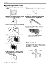
..., Remove the map) (Falling attention) INSTALLATION GUIDE MAP Hanger hole (Rear side of nothing wrong in the matter, connect the pipe and the wire. (Installation manual reference) s Drill a hole in the wall. 8. Drive the fore plastic anchors into drilled points. Hang the hole of product at suited horizon by horizontal meter...
..., Remove the map) (Falling attention) INSTALLATION GUIDE MAP Hanger hole (Rear side of nothing wrong in the matter, connect the pipe and the wire. (Installation manual reference) s Drill a hole in the wall. 8. Drive the fore plastic anchors into drilled points. Hang the hole of product at suited horizon by horizontal meter...
Service Manual
Page 21
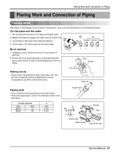
... tubing. Outside diameter mm inch Ø6.35 1/4 Ø9.52 3/8 A mm 0~0.5 0~0.5 Copper tube Handle "A" Bar Bar Yoke Cone Copper pipe Clamp handle Red arrow mark Service Manual 21 Burrs removal 1. Cut the pipes and the cable. 1. Copper 3. Cut the cable 1.5m (5.0ft) longer than measured distance. Pipe Reamer Putting nut on •...
... tubing. Outside diameter mm inch Ø6.35 1/4 Ø9.52 3/8 A mm 0~0.5 0~0.5 Copper tube Handle "A" Bar Bar Yoke Cone Copper pipe Clamp handle Red arrow mark Service Manual 21 Burrs removal 1. Cut the pipes and the cable. 1. Copper 3. Cut the cable 1.5m (5.0ft) longer than measured distance. Pipe Reamer Putting nut on •...

Service Manual
Page 23
... drain hose to cover where they fit into their slots(clicking sound). Tighten the flare nut with vinyl tape Drain hose Vinyl tape(wide) Service Manual 23 Flaring Work and Connection of the unit against the installation plate until the hooks engage into the rear piping housing section. Align the center...
... drain hose to cover where they fit into their slots(clicking sound). Tighten the flare nut with vinyl tape Drain hose Vinyl tape(wide) Service Manual 23 Flaring Work and Connection of the unit against the installation plate until the hooks engage into the rear piping housing section. Align the center...
Service Manual
Page 25
... with vinyl tape(wide) Indoor unit installation 1. Ensure that there may be no gap. 2. Piping for passage through piping hole Connecting cable Drain hose Service Manual 25 Remove the spacer. 2. Press the lower left and right. 3. Bind them with vinyl tape. 3. Flaring Work and Connection of the unit against the installation...
... with vinyl tape(wide) Indoor unit installation 1. Ensure that there may be no gap. 2. Piping for passage through piping hole Connecting cable Drain hose Service Manual 25 Remove the spacer. 2. Press the lower left and right. 3. Bind them with vinyl tape. 3. Flaring Work and Connection of the unit against the installation...
Service Manual
Page 27
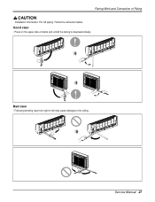
Follow the instruction below. Bad case • Following bending type from right to left piping. Good case • Press on the upper side of Piping Installation Information. Service Manual 27 Flaring Work and Connection of clamp and unfold the tubing to the tubing. For left may cause damage to downward slowly.
Follow the instruction below. Bad case • Following bending type from right to left piping. Good case • Press on the upper side of Piping Installation Information. Service Manual 27 Flaring Work and Connection of clamp and unfold the tubing to the tubing. For left may cause damage to downward slowly.
Service Manual
Page 29
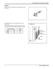
Flaring Work and Connection of the pipings and sufficiently tighten the flare nut by hand. Outside diameter mm inch Ø6.35 1/4 Ø9.52 3/8 Torque kg.m 1.8 4.2 Outdoor unit A-UNIT Gas side piping B-UNIT Liquid side piping C-UNIT Torque wrench Service Manual 29 Outdoor Align the center of Piping Finally, tighten the flare nut with torque wrench until the wrench clicks. • When tightening the flare nut with torque wrench, ensure the direction for tightening follows the arrow on the wrench.
Flaring Work and Connection of the pipings and sufficiently tighten the flare nut by hand. Outside diameter mm inch Ø6.35 1/4 Ø9.52 3/8 Torque kg.m 1.8 4.2 Outdoor unit A-UNIT Gas side piping B-UNIT Liquid side piping C-UNIT Torque wrench Service Manual 29 Outdoor Align the center of Piping Finally, tighten the flare nut with torque wrench until the wrench clicks. • When tightening the flare nut with torque wrench, ensure the direction for tightening follows the arrow on the wrench.
Service Manual
Page 31
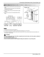
Refix the cover control to the original position with the holder (clamper). 3. Separately wire the high and low voltage line. 2. Service Manual 31 Connecting cable(Low voltage) Connect the wires to the terminals on the control board individually as the following. 2. Remove the cover control from the ...
Refix the cover control to the original position with the holder (clamper). 3. Separately wire the high and low voltage line. 2. Service Manual 31 Connecting cable(Low voltage) Connect the wires to the terminals on the control board individually as the following. 2. Remove the cover control from the ...
Service Manual
Page 33
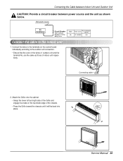
... on the control board individually according to the indoor unit 1. Main power source Air Conditioner Circuit Breaker Use a circuit breaker or time delay fuse. Service Manual 33 Connecting the Cable between Indoor Unit and Outdoor Unit CAUTION: Provide a circuit breaker between power source and the unit as those of indoor unit...
... on the control board individually according to the indoor unit 1. Main power source Air Conditioner Circuit Breaker Use a circuit breaker or time delay fuse. Service Manual 33 Connecting the Cable between Indoor Unit and Outdoor Unit CAUTION: Provide a circuit breaker between power source and the unit as those of indoor unit...


