
Service Manual
Page 2
... this Manual ...4 Safety Precautions...5 Dimensions...11 Indoor Unit...11 Outdoor Unit ...12 Product Specifications ...13 Installation ...15 Installation Parts...15 Installation Tools...15 Select the best location ...16 Piping length and elevation ...17 Fixing Installation Plate(Standart Type 18 ... Refrigeration Cycle Diagram ...64 Self-diagnosis Function ...65 Cycle Troubleshooting Guide...66 Electronic Parts Troubleshooting Guide 67 General Information...72 2-way, 3-way Valve ...78 Exploded View & Replacement Parts List 82 Indoor Unit ...82 Outdoor Unit ...86 2 Multi type Air Conditioner
... this Manual ...4 Safety Precautions...5 Dimensions...11 Indoor Unit...11 Outdoor Unit ...12 Product Specifications ...13 Installation ...15 Installation Parts...15 Installation Tools...15 Select the best location ...16 Piping length and elevation ...17 Fixing Installation Plate(Standart Type 18 ... Refrigeration Cycle Diagram ...64 Self-diagnosis Function ...65 Cycle Troubleshooting Guide...66 Electronic Parts Troubleshooting Guide 67 General Information...72 2-way, 3-way Valve ...78 Exploded View & Replacement Parts List 82 Indoor Unit ...82 Outdoor Unit ...86 2 Multi type Air Conditioner
Service Manual
Page 7
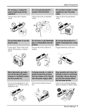
... or smoke comes from the window before turn off the gas and open a window for a long product. Do not allow water to run into electric parts. • It may cause There is risk of fire or failure of product. • Oxygen deficiency could occur. time. • There is risk of fire...
... or smoke comes from the window before turn off the gas and open a window for a long product. Do not allow water to run into electric parts. • It may cause There is risk of fire or failure of product. • Oxygen deficiency could occur. time. • There is risk of fire...
Service Manual
Page 9
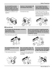
... air filter. They are very sharp! • It may cause product failure. • There is risk of fire, electric shock, or damage to the plastic parts of the product. • There is risk of damage or loss of personal injury. Do not touch the metal... parts of air flow. Do not install the product where it will be exposed to your neighbors. s Operational Do not expose the skin directly to cool ...
... air filter. They are very sharp! • It may cause product failure. • There is risk of fire, electric shock, or damage to the plastic parts of the product. • There is risk of damage or loss of personal injury. Do not touch the metal... parts of air flow. Do not install the product where it will be exposed to your neighbors. s Operational Do not expose the skin directly to cool ...
Service Manual
Page 10
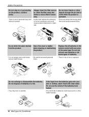
... the product is operated. • There is risk of the air conditioner and could cause product malfunction or damage. • There are sharp and moving parts that could cause personal injury. injury. Do not mix old and new batteries or different types of batteries. • There is risk of personal injury...
... the product is operated. • There is risk of the air conditioner and could cause product malfunction or damage. • There are sharp and moving parts that could cause personal injury. injury. Do not mix old and new batteries or different types of batteries. • There is risk of personal injury...
Service Manual
Page 13
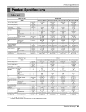
... Rate Dimensions (W*H*D) Net Weight Piping Connection Liquid Gas Drain hose (ID Ø) Packing Dimension (W*H*D) Stuffing Quantity With(Without) S/Parts kcal/h(W) Btu/h kcal/h(W) Btu/h CMM(CFM) °C W V A EA/inch(mm) dBA inch(mm) l/h inch(mm...Dehumidification Rate Dimensions (W*H*D) Net Weight Piping Connection Liquid Gas Drain hose (ID Ø) Packing Dimension (W*H*D) Stuffing Quantity With(Without) S/Parts kcal/h(W) Btu/h kcal/h(W) Btu/h CMM(CFM) °C W Artcool AMNC093APM0(LMAN090CNS) AMNH093APM0(LMAN090HNS) AMNC123APM0(LMAN120CNS) AMNH123APM0(LMAN120HNS) ...
... Rate Dimensions (W*H*D) Net Weight Piping Connection Liquid Gas Drain hose (ID Ø) Packing Dimension (W*H*D) Stuffing Quantity With(Without) S/Parts kcal/h(W) Btu/h kcal/h(W) Btu/h CMM(CFM) °C W V A EA/inch(mm) dBA inch(mm) l/h inch(mm...Dehumidification Rate Dimensions (W*H*D) Net Weight Piping Connection Liquid Gas Drain hose (ID Ø) Packing Dimension (W*H*D) Stuffing Quantity With(Without) S/Parts kcal/h(W) Btu/h kcal/h(W) Btu/h CMM(CFM) °C W Artcool AMNC093APM0(LMAN090CNS) AMNH093APM0(LMAN090HNS) AMNC123APM0(LMAN120CNS) AMNH123APM0(LMAN120HNS) ...
Service Manual
Page 15
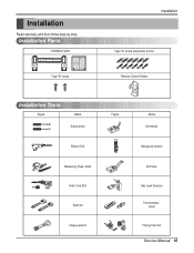
Installation Read carefully, and then follow step by step. Installation Parts Installation plate Type "B" screw Installation Type "A" screw and plastic anchor Remote Control Holder Installation Tools Figure Name Screw driver Electric Drill Measuring Tape, Knife Hole Core Drill Spanner Torque wrench Figure Name Ohmmeter Hexagonal wrench Ammeter Gas Leak Detector Thermometer, Level Flaring Tool Set Service Manual 15
Installation Read carefully, and then follow step by step. Installation Parts Installation plate Type "B" screw Installation Type "A" screw and plastic anchor Remote Control Holder Installation Tools Figure Name Screw driver Electric Drill Measuring Tape, Knife Hole Core Drill Spanner Torque wrench Figure Name Ohmmeter Hexagonal wrench Ammeter Gas Leak Detector Thermometer, Level Flaring Tool Set Service Manual 15
Service Manual
Page 19
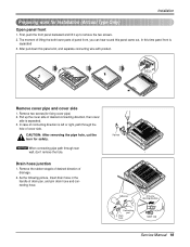
... panel front is left or right, path through rear wall, don't remove the hole. Drain hose junction 1. Pipe hole Adhesive Only one desiring direction Connecting part Drain hose rubber cap Service Manual 19 Pull up to remove the two screws. 2. Panel Front Connector Remove cover pipe and cover side 1. In case...
... panel front is left or right, path through rear wall, don't remove the hole. Drain hose junction 1. Pipe hole Adhesive Only one desiring direction Connecting part Drain hose rubber cap Service Manual 19 Pull up to remove the two screws. 2. Panel Front Connector Remove cover pipe and cover side 1. In case...
Service Manual
Page 20
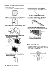
...the matter, connect the pipe and the wire. (Installation manual reference) s Drill a hole in the wall. 8. In case of the upper parts by screws. (Leave 10mm for connecting pipe as diameter 50mm. (In case of product with light power. Hang the hole of product at the...(Rear side of 30-35mm when piercing a screw point. Drill the piping hole at suited horizon by adhesive tape. Drill the piercing part for hanging product) 10mm INSTALLATION GU 9. INSTAIIATION GUIDE MAP 3. Plastic anchors Plastic anchors 4. Drive the fore plastic anchors into drilled points. Drive...
...the matter, connect the pipe and the wire. (Installation manual reference) s Drill a hole in the wall. 8. In case of the upper parts by screws. (Leave 10mm for connecting pipe as diameter 50mm. (In case of product with light power. Hang the hole of product at the...(Rear side of 30-35mm when piercing a screw point. Drill the piping hole at suited horizon by adhesive tape. Drill the piercing part for hanging product) 10mm INSTALLATION GU 9. INSTAIIATION GUIDE MAP 3. Plastic anchors Plastic anchors 4. Drive the fore plastic anchors into drilled points. Drive...
Service Manual
Page 26
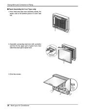
Flaring Work and Connection of panel front Panel Front Connector 3. Assemble connecting lead wire with controller and first fix the upper part of panel front, then match the lower part of Piping s Panel Assembly(Art Cool Type only) 1. Drive two screws. 26 Multi type Air Conditioner First, Check the side cover assembly exactly, Fix power cord in the bottom groove of cover side left. 2.
Flaring Work and Connection of panel front Panel Front Connector 3. Assemble connecting lead wire with controller and first fix the upper part of panel front, then match the lower part of Piping s Panel Assembly(Art Cool Type only) 1. Drive two screws. 26 Multi type Air Conditioner First, Check the side cover assembly exactly, Fix power cord in the bottom groove of cover side left. 2.
Service Manual
Page 31
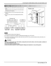
... unit. 1. Service Manual 31 Separately wire the high and low voltage line. 2. Refix the cover control to touch refrigerant tubing, the compressor or any moving parts. Use heat-proof electrical wiring capable of wire and wiring method, etc). • Every wire must be connected firmly. • No wire should be allowed...
... unit. 1. Service Manual 31 Separately wire the high and low voltage line. 2. Refix the cover control to touch refrigerant tubing, the compressor or any moving parts. Use heat-proof electrical wiring capable of wire and wiring method, etc). • Every wire must be connected firmly. • No wire should be allowed...
Service Manual
Page 35
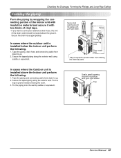
... unit is installed below the indoor unit perform the following . 1. Secure the drain hose appropriately. Tape the piping and connecting cable from entering into electrical parts. Seal a small opening around the pipings with gum type sealer. Checking the Drainage, Forming the Pipings and Long Pipe Setting Forming the piping Form the...
... unit is installed below the indoor unit perform the following . 1. Secure the drain hose appropriately. Tape the piping and connecting cable from entering into electrical parts. Seal a small opening around the pipings with gum type sealer. Checking the Drainage, Forming the Pipings and Long Pipe Setting Forming the piping Form the...
Service Manual
Page 36
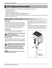
... indoor and outdoor) and both the gas and the liquid side on the outdoor unit are kept closed . • Pressurize the system to corrosion of parts in the system rises. 2. Moisture in the refrigerant circuit may lead to no more than its bottom when you pressurize the system.
... indoor and outdoor) and both the gas and the liquid side on the outdoor unit are kept closed . • Pressurize the system to corrosion of parts in the system rises. 2. Moisture in the refrigerant circuit may lead to no more than its bottom when you pressurize the system.

Service Manual
Page 52
... Connector Motor Connector 52 Multi type Air Conditioner Pull the control box out from the control box and disconnect other wires. - Lift the both lower parts of panel front. - After pull down this panel a bit, separate connecting wire with product. 2. Pull the cover control out from the chassis carefully. Remove securing...
... Connector Motor Connector 52 Multi type Air Conditioner Pull the control box out from the control box and disconnect other wires. - Lift the both lower parts of panel front. - After pull down this panel a bit, separate connecting wire with product. 2. Pull the cover control out from the chassis carefully. Remove securing...
Service Manual
Page 67
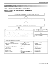
... the main power again. tion of Micom is O.K. • Check CN-DISP1 The operation check of Indoor/Outdoor connecting cable (each color) • The P.W.B. Electronic Parts Troubleshooting Guide ❇ Refer to the unit. • The connecting method of the P.C.B. Trouble 1 The Product doesn't operate at all. NO Check the voltage of...
... the main power again. tion of Micom is O.K. • Check CN-DISP1 The operation check of Indoor/Outdoor connecting cable (each color) • The P.W.B. Electronic Parts Troubleshooting Guide ❇ Refer to the unit. • The connecting method of the P.C.B. Trouble 1 The Product doesn't operate at all. NO Check the voltage of...

Service Manual
Page 68
... the remote controller door is fault, it is displayed in the Sleeping Mode, the wind speed is driven by the remote controller. Caused by other parts except the remote controller When the mark ( ) is impossible to operate temperature regulating(v / w) and wind speed selecting. When the compressor stopped Indoor Fan is set...
... the remote controller door is fault, it is displayed in the Sleeping Mode, the wind speed is driven by the remote controller. Caused by other parts except the remote controller When the mark ( ) is impossible to operate temperature regulating(v / w) and wind speed selecting. When the compressor stopped Indoor Fan is set...
Service Manual
Page 71
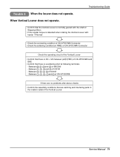
Between 1 , 2 , 3 , 4 and 5 of CN-UP/DOWN If there are no problems after above checks • Confirm the assembly conditions that are catching and interfering parts in the rotation radial of IC01M - Between 2 , 3 , 4 and 5 of the Vertical Louver Service Manual 71 Between 12 , 13 , 14 , 15 of CN-UP/DOWN and ...
Between 1 , 2 , 3 , 4 and 5 of CN-UP/DOWN If there are no problems after above checks • Confirm the assembly conditions that are catching and interfering parts in the rotation radial of IC01M - Between 2 , 3 , 4 and 5 of the Vertical Louver Service Manual 71 Between 12 , 13 , 14 , 15 of CN-UP/DOWN and ...
Service Manual
Page 81
... FLOW 5901A20017F 5901A20017F 5901A20017H 5901A20017H R 733010 PLATE ASSEMBLY,INSTALLATION 3301A20020C 3301A20020C 3301A20020A 3301A20020A R 135500 COVER 3550A30262A 3550A30262A 3550A30315A 3550A30315A R NOTE) *Please ensure GCSC since these parts may be changed depending upon the buyer's request. (GCSC WEBSITE http://biz.LGservice.com) Service Manual 81...
... FLOW 5901A20017F 5901A20017F 5901A20017H 5901A20017H R 733010 PLATE ASSEMBLY,INSTALLATION 3301A20020C 3301A20020C 3301A20020A 3301A20020A R 135500 COVER 3550A30262A 3550A30262A 3550A30315A 3550A30315A R NOTE) *Please ensure GCSC since these parts may be changed depending upon the buyer's request. (GCSC WEBSITE http://biz.LGservice.com) Service Manual 81...
Service Manual
Page 83
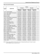
Exploded View & Replacement Parts List Parts List (SP3 chassis) LOCATION No. AMNH093APM0 AMNC093APM0 AMNH123APM0 AMNC123APM0 (LMAN090HNS) (LMAN090CNS) (LMAN120HNS) (LMAN120CNS) SVC CODE 131410 CHASSIS ASSEMBLY 3141A20030C 3141A20030C 3141A20030C 3141A20030C ... R 354210 EVAPORATOR ASSEMBLY,FIRST 5421A20072A 5421A20072A 5421A20072A 5421A20072A R 359012 FAN,TURBO 5900A00003A 5900A00003A 5900A00003A 5900A00003A R NOTE) *Please ensure GCSC since these parts may be changed depending upon the buyer's request. (GCSC WEBSITE http://biz.LGservice.com) Service Manual 83 DESCRIPTION...
Exploded View & Replacement Parts List Parts List (SP3 chassis) LOCATION No. AMNH093APM0 AMNC093APM0 AMNH123APM0 AMNC123APM0 (LMAN090HNS) (LMAN090CNS) (LMAN120HNS) (LMAN120CNS) SVC CODE 131410 CHASSIS ASSEMBLY 3141A20030C 3141A20030C 3141A20030C 3141A20030C ... R 354210 EVAPORATOR ASSEMBLY,FIRST 5421A20072A 5421A20072A 5421A20072A 5421A20072A R 359012 FAN,TURBO 5900A00003A 5900A00003A 5900A00003A 5900A00003A R NOTE) *Please ensure GCSC since these parts may be changed depending upon the buyer's request. (GCSC WEBSITE http://biz.LGservice.com) Service Manual 83 DESCRIPTION...
Service Manual
Page 85
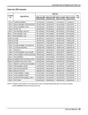
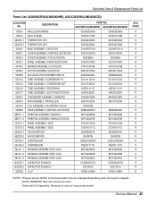
... 6750U-L048A SVC CODE R R R R R R R R R R R R R R R R R R R R R R R R R R R R R R R R R NOTE) *Please ensure GCSC since these parts may be changed depending upon the buyer's request. (GCSC WEBSITE http://biz.LGservice.com) Solenoid(Coil Assembly, Reverse) is only for heat pump model. Exploded... View & Replacement Parts List Parts List (A3UH363FA0(LMU360HE), A3UC363FA0(LMU360CE)) LOCATION No. DESCRIPTION 135301 135314 263230-1 263230-2 430410 435511 435512 437211 447910 546810 548490 552112 552113 ...
... 6750U-L048A SVC CODE R R R R R R R R R R R R R R R R R R R R R R R R R R R R R R R R R NOTE) *Please ensure GCSC since these parts may be changed depending upon the buyer's request. (GCSC WEBSITE http://biz.LGservice.com) Solenoid(Coil Assembly, Reverse) is only for heat pump model. Exploded... View & Replacement Parts List Parts List (A3UH363FA0(LMU360HE), A3UC363FA0(LMU360CE)) LOCATION No. DESCRIPTION 135301 135314 263230-1 263230-2 430410 435511 435512 437211 447910 546810 548490 552112 552113 ...


