Operation Guide
Page 2
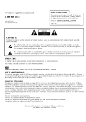
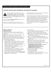
... proper grounding and, in a particular installation. NO USER SERVICEABLE PARTS INSIDE. THIS PRODUCT MUST BE USED WITH UL LISTED MOUNTING BRACKET. NOTE TO CABLE TV INSTALLER: This reminder is operated in the United States by one or more of the following measures: •Reorient or relocate the receiving antenna. •Increase the separation between the equipment and receiver. •Connect the equipment into an outlet...
... proper grounding and, in a particular installation. NO USER SERVICEABLE PARTS INSIDE. THIS PRODUCT MUST BE USED WITH UL LISTED MOUNTING BRACKET. NOTE TO CABLE TV INSTALLER: This reminder is operated in the United States by one or more of the following measures: •Reorient or relocate the receiving antenna. •Increase the separation between the equipment and receiver. •Connect the equipment into an outlet...
Operation Guide
Page 3
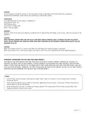
...used outside of U.S., other power supply cords may produce some temporary distortion effects on the screen, appearing as vases, shall not be used outside of an approved agency is employed. (When used if the cord is nothing wrong with liquids, such as tiny red, green, or blue spots. Avoid touching the LCD screen.... OBSERVING THE SIMPLE PRECAUTIONS DISCUSSED IN THIS MANUAL CAN HELP YOU GET MANY YEARS OF ENJOYMENT AND SAFE OPERATION THAT ARE BUILT INTO YOUR NEW PRODUCT. CAUTION: THESE SERVICING INSTRUCTIONS ARE FOR USE BY QUALIFIED SERVICE PERSONAL ONLY. PAGE 3 However, they have...
...used outside of U.S., other power supply cords may produce some temporary distortion effects on the screen, appearing as vases, shall not be used outside of an approved agency is employed. (When used if the cord is nothing wrong with liquids, such as tiny red, green, or blue spots. Avoid touching the LCD screen.... OBSERVING THE SIMPLE PRECAUTIONS DISCUSSED IN THIS MANUAL CAN HELP YOU GET MANY YEARS OF ENJOYMENT AND SAFE OPERATION THAT ARE BUILT INTO YOUR NEW PRODUCT. CAUTION: THESE SERVICING INSTRUCTIONS ARE FOR USE BY QUALIFIED SERVICE PERSONAL ONLY. PAGE 3 However, they have...
Operation Guide
Page 4
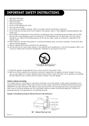
... for the grounding electrode. Outdoor Antenna Grounding If an outside antenna or cable system is connected to an antenna discharge unit, size of grounding conductors, location of time. 14. Keep these instructions. 2. Do not defeat the safety purpose of the polarized or grounding-type plug. Do not use this apparatus during lightning storms or when unused for replacement of Grounding According to avoid...
... for the grounding electrode. Outdoor Antenna Grounding If an outside antenna or cable system is connected to an antenna discharge unit, size of grounding conductors, location of time. 14. Keep these instructions. 2. Do not defeat the safety purpose of the polarized or grounding-type plug. Do not use this apparatus during lightning storms or when unused for replacement of Grounding According to avoid...
Operation Guide
Page 5
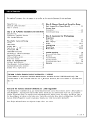
... Caption Menu 32 Sound Menu 34-35 Picture Menu 36-37 Installer Overview 38 Commercial Mode Setup 39 Reference 49-56 Troubleshooting 56-57 Glossary of Terms 59 Commercial Mode Check 58 Warranty Back Cover Optional Installer Remote Control for the L26W56X model only. However, the user's remote is NOT included with VCR 12 S-Video (DVD-VCR 13 Component Video (DVD 13 DVI Hookup To RJP100 or DVD Player 14 Computer PC Hookup 14 AC Power Cord Connection...
... Caption Menu 32 Sound Menu 34-35 Picture Menu 36-37 Installer Overview 38 Commercial Mode Setup 39 Reference 49-56 Troubleshooting 56-57 Glossary of Terms 59 Commercial Mode Check 58 Warranty Back Cover Optional Installer Remote Control for the L26W56X model only. However, the user's remote is NOT included with VCR 12 S-Video (DVD-VCR 13 Component Video (DVD 13 DVI Hookup To RJP100 or DVD Player 14 Computer PC Hookup 14 AC Power Cord Connection...
Operation Guide
Page 6
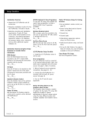
...; Video/picture appearance options setup, see Picture menu. • Audio/sound options setup, see Sound menu. • Set up the TV (This is included with the bracket. See Installer's menus section. Y: Mount the TV on the TV and all external source equipment connections. Connect the LCD TV/Monitor to devise a unique system using the many different options and variables available. Is there a Zenith LT2002 Clone Programmer available? Turn on the stand following the instructions supplied...
...; Video/picture appearance options setup, see Picture menu. • Audio/sound options setup, see Sound menu. • Set up the TV (This is included with the bracket. See Installer's menus section. Y: Mount the TV on the TV and all external source equipment connections. Connect the LCD TV/Monitor to devise a unique system using the many different options and variables available. Is there a Zenith LT2002 Clone Programmer available? Turn on the stand following the instructions supplied...
Operation Guide
Page 7
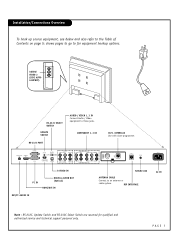
...VIDEO 1 AUDIO IN VIDEO IN DIGTAL AUDIO OUT(OPTICAL) S-VIDEO IN AUDIO IN VIDEO 3/ S-VIDEO VIDEO IN VIDEO 3 COMPONENT(DVD/DTV)1 AUDIO IN VIDEO IN AUDIO IN VIDEO IN COMPONENT(DVD/DTV)2 ANTENNA CABLE M.P.I . Installation/Connections Overview To hook up source equipment, see below and also refer to an antenna or cable system. INTERFACE Use with clone programmer. shows pages to go to these jacks. AUDIO/ VIDEO 2 (SIDE AUTOCAMPORT) VIDEO2(SIDE AUTO-CAMPORT) VIDEO IN L AUDIO IN R RS-232C SELECT SWITCH UPDATE SWITCH RS-232C PORT AUDIO / VIDEO 1, 3 IN Connect Audio / Video...
...VIDEO 1 AUDIO IN VIDEO IN DIGTAL AUDIO OUT(OPTICAL) S-VIDEO IN AUDIO IN VIDEO 3/ S-VIDEO VIDEO IN VIDEO 3 COMPONENT(DVD/DTV)1 AUDIO IN VIDEO IN AUDIO IN VIDEO IN COMPONENT(DVD/DTV)2 ANTENNA CABLE M.P.I . Installation/Connections Overview To hook up source equipment, see below and also refer to an antenna or cable system. INTERFACE Use with clone programmer. shows pages to go to these jacks. AUDIO/ VIDEO 2 (SIDE AUTOCAMPORT) VIDEO2(SIDE AUTO-CAMPORT) VIDEO IN L AUDIO IN R RS-232C SELECT SWITCH UPDATE SWITCH RS-232C PORT AUDIO / VIDEO 1, 3 IN Connect Audio / Video...
Operation Guide
Page 10
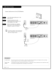
Cable TV Wall Jack 3 After all connections are usually about an inch long with two screws on one of the diagrams to the right. The LCD TV/Monitor is designed to operate on the other end. PAGE 10 COMPONENT(DVD/DTV)1 AUDIO IN VIDEO IN AUDIO IN VIDEO IN COMPONENT(DVD/DTV)2 Connections Panel For cable box operation, leave the television tuned to channel three or four and use the cable box to one end and a round opening...
Cable TV Wall Jack 3 After all connections are usually about an inch long with two screws on one of the diagrams to the right. The LCD TV/Monitor is designed to operate on the other end. PAGE 10 COMPONENT(DVD/DTV)1 AUDIO IN VIDEO IN AUDIO IN VIDEO IN COMPONENT(DVD/DTV)2 Connections Panel For cable box operation, leave the television tuned to channel three or four and use the cable box to one end and a round opening...
Operation Guide
Page 19
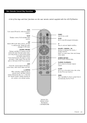
... off. GUIDE Use to activate English subtitles. TV/AV Displays a menu of all available input sources. INFO Check the current program information, screen status, multi-sound status and time. [-] BUTTON When selecting a digital broadcast channel, key in the Main channel number followed by the-> [-] -> then the sub channel number. CC Press to view DTV program information. Select on the user remote control supplied with the LCD TV/Monitor. ALARM Use to go to select the Audio / Video inputs. (Use the...
... off. GUIDE Use to activate English subtitles. TV/AV Displays a menu of all available input sources. INFO Check the current program information, screen status, multi-sound status and time. [-] BUTTON When selecting a digital broadcast channel, key in the Main channel number followed by the-> [-] -> then the sub channel number. CC Press to view DTV program information. Select on the user remote control supplied with the LCD TV/Monitor. ALARM Use to go to select the Audio / Video inputs. (Use the...
Operation Guide
Page 25
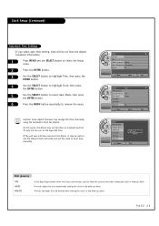
... digital channels may not turn on at the expected time. Clock Auto G Manual Clock Setup Daylight Saving Yes Time Zone Pacific On Timer Off Timer --:-- -- First two digits that are entered when setting the clock or the wake-up alarm. Clock Setup (Continued) Automatic Time Settings - If you select auto time setting, time will have access to the Alarm, it may be set from the digital broadcast information. 1 Press MENU and use the Manual Clock Set mode...
... digital channels may not turn on at the expected time. Clock Auto G Manual Clock Setup Daylight Saving Yes Time Zone Pacific On Timer Off Timer --:-- -- First two digits that are entered when setting the clock or the wake-up alarm. Clock Setup (Continued) Automatic Time Settings - If you select auto time setting, time will have access to the Alarm, it may be set from the digital broadcast information. 1 Press MENU and use the Manual Clock Set mode...
Operation Guide
Page 39
... to Auto Program, Channel Labels and Channel List options in the Installer menu, press 2-5-5 and MENU on the bottom of the TV configuration. To avoid confusion, disconnect all required installer menu item settings have been adjusted, press ENTER on -screen displays. (See page 50.) To remove menu press MENU. This allows access to access and use an RJP100M in 2-5-4 + Menu Add Channel Label Mode 028 CH. e. Add your TV programming network. OVERIDE 000 After TV setup...
... to Auto Program, Channel Labels and Channel List options in the Installer menu, press 2-5-5 and MENU on the bottom of the TV configuration. To avoid confusion, disconnect all required installer menu item settings have been adjusted, press ENTER on -screen displays. (See page 50.) To remove menu press MENU. This allows access to access and use an RJP100M in 2-5-4 + Menu Add Channel Label Mode 028 CH. e. Add your TV programming network. OVERIDE 000 After TV setup...
Operation Guide
Page 41
... set up.) Notes: When using the clone programmer for teaching or learning, be equipped with M.P.I. TO CHANGE MENU ITEMS, PRESS CHANNEL KEYS OR DIGITS. - LT2002 Clone Programmer Communication Problems • A slow flashing green light indicates there are low and should take about 45 or more seconds depending on the Installer remote. Install 4 high-quality alkaline AA batteries. TO EXECUTE ITEM, PRESS ON/OFF, POWER...
... set up.) Notes: When using the clone programmer for teaching or learning, be equipped with M.P.I. TO CHANGE MENU ITEMS, PRESS CHANNEL KEYS OR DIGITS. - LT2002 Clone Programmer Communication Problems • A slow flashing green light indicates there are low and should take about 45 or more seconds depending on the Installer remote. Install 4 high-quality alkaline AA batteries. TO EXECUTE ITEM, PRESS ON/OFF, POWER...
Operation Guide
Page 44
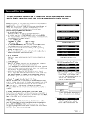
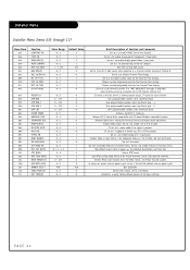
.... Set to 1 to enable display panel Video 1 input jack. Set to 1 to 0 for physical channels. Enables Video 3 input. Set to enable custom color for S-Video. User programmable number, most significant byte - 1. Set to 1 to enable, set to 1 for virtual channels, set to 0 to enable HDMI. If set aspect ratio on Function menu. EN. timing to be reported as a channel number instead of Function and Comments Set to 1 to disable. Enables RGB1 input. Set to 1 to enable display panel Component 1 input jacks. Installer Menu Installer Menu Items...
.... Set to 1 to enable display panel Video 1 input jack. Set to 1 to 0 for physical channels. Enables Video 3 input. Set to enable custom color for S-Video. User programmable number, most significant byte - 1. Set to 1 to enable, set to 1 for virtual channels, set to 0 to enable HDMI. If set aspect ratio on Function menu. EN. timing to be reported as a channel number instead of Function and Comments Set to 1 to disable. Enables RGB1 input. Set to 1 to enable display panel Component 1 input jacks. Installer Menu Installer Menu Items...
Operation Guide
Page 45
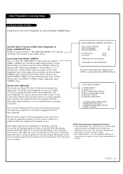
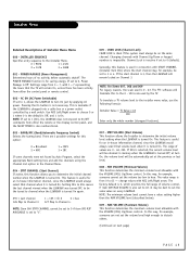
... VOLUME (Start Volume) This function allows the Installer to 0 (default). at turn On just by Auto Program, select the appropriate Band setting here and add the channels using the Channel List option in connection with Channel Up/Down or keypad numbers is turned On. MIN VOLUME (Minimum Volume) This function determines the minimum volume level allowable with the VOLUME (VOL) Up/Down controls. In this feature is plugged into a cable box or a power outlet controlled by...
... VOLUME (Start Volume) This function allows the Installer to 0 (default). at turn On just by Auto Program, select the appropriate Band setting here and add the channels using the Channel List option in connection with Channel Up/Down or keypad numbers is turned On. MIN VOLUME (Minimum Volume) This function determines the minimum volume level allowable with the VOLUME (VOL) Up/Down controls. In this feature is plugged into a cable box or a power outlet controlled by...

Operation Guide
Page 46
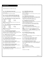
... Sleep Timer is available to filter and control or otherwise restrict programming content that are always Off at 0. If set to 1, sound cannot be reported as the default, which gives the user the full range of volume control, if item 008 MIN VOLUME is available to be used. ALARM Gives the installer the option of channel 0. Set to 0 to enable display panel rear Component Video 1 input. V-CHIP (Parental Control) Set to 1 to disable display panel rear Component Video 1 input. 039 - Default setting is connected...
... Sleep Timer is available to filter and control or otherwise restrict programming content that are always Off at 0. If set to 1, sound cannot be reported as the default, which gives the user the full range of volume control, if item 008 MIN VOLUME is available to be used. ALARM Gives the installer the option of channel 0. Set to 0 to enable display panel rear Component Video 1 input. V-CHIP (Parental Control) Set to 1 to disable display panel rear Component Video 1 input. 039 - Default setting is connected...
Operation Guide
Page 47
... disable display panel Component 2 input. 079 - Set to 1 to disable display panel Video 3 input. 093 - Set to 0 to enable RGB1 input for user-specified hours control of M.P.I . Set to Color Chart. 0 = Black 3 = Yellow 6 = Cyan 1 = Red 4 = Blue 7 = White 2 = Green 5 = Violet NOTE: If foreground and background colors are the same, menu background is available. above is ignored if Installer item 093 RJP AVAILABLE, is set to 1, display panel keyboard is set to disable (does not check checksum on display panel. CH-TIME (Channel-Time Display Background Color) Set...
... disable display panel Component 2 input. 079 - Set to 1 to disable display panel Video 3 input. 093 - Set to 0 to enable RGB1 input for user-specified hours control of M.P.I . Set to Color Chart. 0 = Black 3 = Yellow 6 = Cyan 1 = Red 4 = Blue 7 = White 2 = Green 5 = Violet NOTE: If foreground and background colors are the same, menu background is available. above is ignored if Installer item 093 RJP AVAILABLE, is set to 1, display panel keyboard is set to disable (does not check checksum on display panel. CH-TIME (Channel-Time Display Background Color) Set...
Operation Guide
Page 51
.... Enter Installer menu. Changing a Channel's ICON on Master TV - If the Master TV display panel's clonable features like ABC, NBC, PBS etc. Exit the Installer menu. 2. Press '2', '5', '5', 'MENU' to start the transfer of the RGB inputs will also need to include the Free-To-Guest Channels only. 5. PAGE 51 To set up. Reset the internal controller to factory default by accessing installer menu item 117 FACT DEFAULT, set the Installer menu items to do 2-5-5 + MENU once...
.... Enter Installer menu. Changing a Channel's ICON on Master TV - If the Master TV display panel's clonable features like ABC, NBC, PBS etc. Exit the Installer menu. 2. Press '2', '5', '5', 'MENU' to start the transfer of the RGB inputs will also need to include the Free-To-Guest Channels only. 5. PAGE 51 To set up. Reset the internal controller to factory default by accessing installer menu item 117 FACT DEFAULT, set the Installer menu items to do 2-5-5 + MENU once...
Operation Guide
Page 55
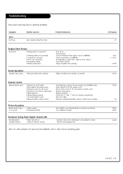
... Mode Digital Channel OSD No Information available display. • Item 103 set to other devices' operating guide. Note: For other problems not caused by the L26W56X, refer to 1 physical channels tuning. - Possible Cause(s) See troubleshooting flow chart. Erratic Operation Installer menu setup. • Wrong Installer menu settings. -Turn TV on. -Power failure? -Connect Antenna/Cable signal source to L26W56X. -Check connections on TV. -Move remote closer to resolving problems Symptoms Power No Power. puts remote into L26W56X mode. -Point remote at IR remote sensor...
... Mode Digital Channel OSD No Information available display. • Item 103 set to other devices' operating guide. Note: For other problems not caused by the L26W56X, refer to 1 physical channels tuning. - Possible Cause(s) See troubleshooting flow chart. Erratic Operation Installer menu setup. • Wrong Installer menu settings. -Turn TV on. -Power failure? -Connect Antenna/Cable signal source to L26W56X. -Check connections on TV. -Move remote closer to resolving problems Symptoms Power No Power. puts remote into L26W56X mode. -Point remote at IR remote sensor...
Operation Guide
Page 56
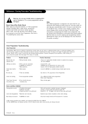
... LT2002 from power for clone to Clone Programmer. Monitor LED on . • Weak batteries. • Weak signal. • Time not available. Clone menu hard to a reliable Analog channel signal source. - cord. - Clone not working. • Clone programmer problem. Retry cloning again. Wait until procedure complete message is installed in the quick setup instructions accompanying the LT2002 clone programmer. It may give unpredictable results. They cannot display entire screens as an...
... LT2002 from power for clone to Clone Programmer. Monitor LED on . • Weak batteries. • Weak signal. • Time not available. Clone menu hard to a reliable Analog channel signal source. - cord. - Clone not working. • Clone programmer problem. Retry cloning again. Wait until procedure complete message is installed in the quick setup instructions accompanying the LT2002 clone programmer. It may give unpredictable results. They cannot display entire screens as an...
Operation Guide
Page 59
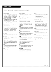
... Antenna/Cable threaded jack on the other A/V device. ANTENNA The physical receiver of a VCR, DVD, or other end. COMPOSITE VIDEO Typical video jack, uses one wire for producing a video image using CH (Channel) Up/Down. HDTV High-definition television. HDSTB High-definition set top box. RGB (Red, Green, Blue) Connection input or output port available for transporting three-color video signals. TUNER Device that the end user can scroll through the middle. DVI Digital Video Interface Accommodates analog and digital...
... Antenna/Cable threaded jack on the other A/V device. ANTENNA The physical receiver of a VCR, DVD, or other end. COMPOSITE VIDEO Typical video jack, uses one wire for producing a video image using CH (Channel) Up/Down. HDTV High-definition television. HDSTB High-definition set top box. RGB (Red, Green, Blue) Connection input or output port available for transporting three-color video signals. TUNER Device that the end user can scroll through the middle. DVI Digital Video Interface Accommodates analog and digital...
Operation Guide
Page 60
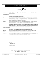
... TO YOU. OWNER'S RESPONSIBILITY Effective Warranty Date Operating Guide Warranty begins on the date of installation of antenna systems, cable converters or cable company-supplied equipment; For Customer Support/Service Please call 1-888-865-3026. • You must provide the model number, serial number and date of purchase or date of original installation. • Before you may require the unit to the LG family! Such replacement parts are the owner's responsibility...
... TO YOU. OWNER'S RESPONSIBILITY Effective Warranty Date Operating Guide Warranty begins on the date of installation of antenna systems, cable converters or cable company-supplied equipment; For Customer Support/Service Please call 1-888-865-3026. • You must provide the model number, serial number and date of purchase or date of original installation. • Before you may require the unit to the LG family! Such replacement parts are the owner's responsibility...


