
Owners Manual
Page 3
.... Owner's Manual Owner's manual D/ATV TV/RADIO TEXT 1 4 2 POWER I/II INPUT MUTE RATIO 7 5 3 MENU LIST 8 0 6 9 Q.VIEW INFO i OK AV MODE or VOL RETUERXNIT GUIDE * RATIO FAV PR INDEX SLEEP TIME SUBTITLE HOLD UPDATE REVEAL ? Lightly wipe any stains or fingerprints on the screen. ACCESSORIES ACCESSORIES Ensure that the following accessories are included with the polishing cloth. Owner's Manual Batteries Remote Control This feature is not available for all models.) LCD TV models x 4 x 4 Bolts for stand assembly...
.... Owner's Manual Owner's manual D/ATV TV/RADIO TEXT 1 4 2 POWER I/II INPUT MUTE RATIO 7 5 3 MENU LIST 8 0 6 9 Q.VIEW INFO i OK AV MODE or VOL RETUERXNIT GUIDE * RATIO FAV PR INDEX SLEEP TIME SUBTITLE HOLD UPDATE REVEAL ? Lightly wipe any stains or fingerprints on the screen. ACCESSORIES ACCESSORIES Ensure that the following accessories are included with the polishing cloth. Owner's Manual Batteries Remote Control This feature is not available for all models.) LCD TV models x 4 x 4 Bolts for stand assembly...
Owners Manual
Page 4
... Guide Mode 61 Button Function in Date Change Mode 61 Button Function in Extended Description Box . . . . . 62 Button Function in Record/Remind Setting Mode . . 62 Button Function in Schedule List Mode 62 PICTURE CONTROL Picture Size (Aspect Ratio) Control 63 Preset Picture Settings - Picture Mode-User option 67 - Screen Setup for Wire Arrangement 15 Positioning Your Display 18 Location 18 Kensington Security System 18 Desktop Pedestal Installation 19 Wall Mount: Horizontal Installation 19 Antenna Connection 20 EXTERNAL EQUIPMENT SETUP HD Receiver Setup 21 Digital Audio out Setup...
... Guide Mode 61 Button Function in Date Change Mode 61 Button Function in Extended Description Box . . . . . 62 Button Function in Record/Remind Setting Mode . . 62 Button Function in Schedule List Mode 62 PICTURE CONTROL Picture Size (Aspect Ratio) Control 63 Preset Picture Settings - Picture Mode-User option 67 - Screen Setup for Wire Arrangement 15 Positioning Your Display 18 Location 18 Kensington Security System 18 Desktop Pedestal Installation 19 Wall Mount: Horizontal Installation 19 Antenna Connection 20 EXTERNAL EQUIPMENT SETUP HD Receiver Setup 21 Digital Audio out Setup...
Owners Manual
Page 5
... Sleep Timer Setting 90 PARENTAL CONTROL / RATINGS Set Password & Lock System 91 Block Programme 92 Parental Control 93 Key Lock 94 TELETEXT Switch On/ Off 95 SIMPLE Text 95 TOP Text 95 FASTEXT 96 Special Teletext Functions 96 DIGITAL TELETEXT Teletext within Digital Service 97 Teletext in Digital Service 97 APPENDIX Initializing (Reset to original factory setting) . . . . 98 Troubleshooting 99 Maintenance 101 Product Specifications 102 Programming the Remote Control 105 IR Codes 107 External Control Device Setup 109 3 Sound Mode 77 Sound Setting Adjustment - User Mode...
... Sleep Timer Setting 90 PARENTAL CONTROL / RATINGS Set Password & Lock System 91 Block Programme 92 Parental Control 93 Key Lock 94 TELETEXT Switch On/ Off 95 SIMPLE Text 95 TOP Text 95 FASTEXT 96 Special Teletext Functions 96 DIGITAL TELETEXT Teletext within Digital Service 97 Teletext in Digital Service 97 APPENDIX Initializing (Reset to original factory setting) . . . . 98 Troubleshooting 99 Maintenance 101 Product Specifications 102 Programming the Remote Control 105 IR Codes 107 External Control Device Setup 109 3 Sound Mode 77 Sound Setting Adjustment - User Mode...

Owners Manual
Page 9
.../50PG10**) Connect audio/video output from various types of equipment. Never attempt to HDMI IN. BACK PANEL INFORMATION A Image shown may differ from an S-VIDEO device. 7 Or DVI (VIDEO) signal to HDMI/DVI port with DVI to HDMI cable. 6 RGB Input Connect the output from a PC. 7 RS-232C IN (CONTROL & SERVICE) PORT Connect to the RS-232C port on DC power. 2 RGB/DVI Audio Input Connect the audio from a PC or DTV. 3 OPTICAL DIGITAL AUDIO OUT Connect digital audio from an external device to...
.../50PG10**) Connect audio/video output from various types of equipment. Never attempt to HDMI IN. BACK PANEL INFORMATION A Image shown may differ from an S-VIDEO device. 7 Or DVI (VIDEO) signal to HDMI/DVI port with DVI to HDMI cable. 6 RGB Input Connect the output from a PC. 7 RS-232C IN (CONTROL & SERVICE) PORT Connect to the RS-232C port on DC power. 2 RGB/DVI Audio Input Connect the audio from a PC or DTV. 3 OPTICAL DIGITAL AUDIO OUT Connect digital audio from an external device to...
Owners Manual
Page 10
... standby mode, these jacks. PCMCIS CARD SLOT 2 RGB/DVI Audio Input Connect the audio from various types of equipment. HDMI IN 3 3 DIGITAL AUDIO OUT OPTICAL Connect digital audio from a PC or DTV. Or DVI (VIDEO) signal to HDMI/DVI port with DVI to HDMI cable. 6 RGB Input Connect the output from an external device to HDMI IN. Never attempt to these jacks. 9 Antenna Input Connect RF antenna to this socket. 13 SERVICE ONLY PORT 7 RS-232C IN (CONTROL & SERVICE) PORT Connect to the RS-232C port...
... standby mode, these jacks. PCMCIS CARD SLOT 2 RGB/DVI Audio Input Connect the audio from various types of equipment. HDMI IN 3 3 DIGITAL AUDIO OUT OPTICAL Connect digital audio from a PC or DTV. Or DVI (VIDEO) signal to HDMI/DVI port with DVI to HDMI cable. 6 RGB Input Connect the output from an external device to HDMI IN. Never attempt to these jacks. 9 Antenna Input Connect RF antenna to this socket. 13 SERVICE ONLY PORT 7 RS-232C IN (CONTROL & SERVICE) PORT Connect to the RS-232C port...

Owners Manual
Page 11
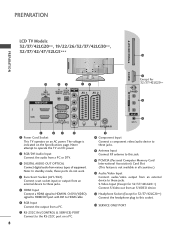
... the Specifications page. The voltage is not available in all countries.) 9 LCD TV Models : 19/22LS4D* PREPARATION 1 2 3 4 5 AV 1 AV 2 HDMI/DVI IN AUDIO IN (RGB/DVI) ANTENNA IN RS-232C IN (CONTROL & SERVICE) RGB (PC) IN PCMCIA CARD SLOT EJECT COMPONENT IN VIDEO AUDIO Y PB PR L R SERVICE ONLY 6 7 8 9 10 1 Power Cord Socket This TV operates on a PC. 8 Component Input Connect a component video/audio device to these jacks. 9 RGB Input Connect the output from an external...
... the Specifications page. The voltage is not available in all countries.) 9 LCD TV Models : 19/22LS4D* PREPARATION 1 2 3 4 5 AV 1 AV 2 HDMI/DVI IN AUDIO IN (RGB/DVI) ANTENNA IN RS-232C IN (CONTROL & SERVICE) RGB (PC) IN PCMCIA CARD SLOT EJECT COMPONENT IN VIDEO AUDIO Y PB PR L R SERVICE ONLY 6 7 8 9 10 1 Power Cord Socket This TV operates on a PC. 8 Component Input Connect a component video/audio device to these jacks. 9 RGB Input Connect the output from an external...

Owners Manual
Page 20
... detailed installation and use the wall mounting bracket (optional parts), fix it carefully so as notebook PCs and LCD projectors. If the TV feels cold to the touch, there may be a small "flicker" when when it for expensive electronic equipment such as not to the user's guide provided with the Kensington Security System. Connect the Kensington Security System cable as tiny red, green, or...
... detailed installation and use the wall mounting bracket (optional parts), fix it carefully so as notebook PCs and LCD projectors. If the TV feels cold to the touch, there may be a small "flicker" when when it for expensive electronic equipment such as not to the user's guide provided with the Kensington Security System. Connect the Kensington Security System cable as tiny red, green, or...

Owners Manual
Page 23
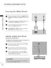
...2 Turn on the remote control. COMPONENT IN VIDEO AUDIO Y PB PR L R 2 Connect the audio output of the digital set top box to the owner's manual for the digital set-top box.) 1 2 4 Select Component input source using the INPUT button on the TV. EXTERNAL EQIPMENT SETUP EXTERNAL EQUIPMENT SETUP ■ To avoid damaging any equipment, never plug in any power cords until you do receive Digital signals from a digital set-top box or other digital external device, refer to the owner's manual for the 22LS4D* models. HD RECEIVER SETUP ■ This TV can receive Digital RF/Cable signals...
...2 Turn on the remote control. COMPONENT IN VIDEO AUDIO Y PB PR L R 2 Connect the audio output of the digital set top box to the owner's manual for the digital set-top box.) 1 2 4 Select Component input source using the INPUT button on the TV. EXTERNAL EQIPMENT SETUP EXTERNAL EQUIPMENT SETUP ■ To avoid damaging any equipment, never plug in any power cords until you do receive Digital signals from a digital set-top box or other digital external device, refer to the owner's manual for the 22LS4D* models. HD RECEIVER SETUP ■ This TV can receive Digital RF/Cable signals...
Owners Manual
Page 24
... TV's audio signal to external audio equipment via the Digital Audio Output (Optical) port. 1 Connect one end of an optical cable to the TV Digital Audio (Optical) Output port. 2 Connect the other end of the digital set-top box to the AUDIO IN (RGB/DVI) jack on the TV. 3 Turn on the digital set -top box.) 4 Select HDMI/DVI or HDMI 1 input source using the INPUT button on the audio equipment. 3 Set the " TV Speaker option - DVI IN AUDIO IN (RGB/DVI) OPTICAL DIGITAL AUDIO OUT COMPONENT IN AV 1 AV VIDEO 1 RGB...
... TV's audio signal to external audio equipment via the Digital Audio Output (Optical) port. 1 Connect one end of an optical cable to the TV Digital Audio (Optical) Output port. 2 Connect the other end of the digital set-top box to the AUDIO IN (RGB/DVI) jack on the TV. 3 Turn on the digital set -top box.) 4 Select HDMI/DVI or HDMI 1 input source using the INPUT button on the audio equipment. 3 Set the " TV Speaker option - DVI IN AUDIO IN (RGB/DVI) OPTICAL DIGITAL AUDIO OUT COMPONENT IN AV 1 AV VIDEO 1 RGB...

Owners Manual
Page 26
... S-VIDEO input on the TV. EXTERNAL EQUIPMENT SETUP EXTERNAL EQIPMENT SETUP Connecting with a S-Video cable (Except for 19/22LS4D*, 32/37/42LG20**, 42/50PG10**) PCMCIA CARD SLOT 1 Connect the S-VIDEO output of the DVD to the AUDIO input jacks on the DVD player, insert a DVD. NOTE G The TV can receive video and audio signals simultaneously when using the INPUT button on the remote control. 5 Refer to the DVD player's manual for operating AV IN 3 instructions. G If the DVD does not support Auto HDMI, you must set the output resolution...
... S-VIDEO input on the TV. EXTERNAL EQUIPMENT SETUP EXTERNAL EQIPMENT SETUP Connecting with a S-Video cable (Except for 19/22LS4D*, 32/37/42LG20**, 42/50PG10**) PCMCIA CARD SLOT 1 Connect the S-VIDEO output of the DVD to the AUDIO input jacks on the DVD player, insert a DVD. NOTE G The TV can receive video and audio signals simultaneously when using the INPUT button on the remote control. 5 Refer to the DVD player's manual for operating AV IN 3 instructions. G If the DVD does not support Auto HDMI, you must set the output resolution...

Owners Manual
Page 28
...select A V 2 input source. Match the jack colours (Video = yellow, Audio Left = white, and Audio Right = red) HDMI IN 3 2 Insert a video tape into the VCR and press PLAY on the VCR. (Refer to the VCR owner's manual.) 3 Select A V 1 input source using the I N P U T button on the remote control. 4 If connected to the VCR owner's manual.) S-VIDEO 3 Select AV3 input source using the INPUT button on S-VIDEO the remote control. HDMI IN 3 VIDEO L/MONO AUDIO R VIDEO L/MONO AUDIO R ! NOTE G Any Euro scart cable used must be signal shielded. AUDIO/ VIDEO (R) AUDIO (L) PCMCIA CARD...
...select A V 2 input source. Match the jack colours (Video = yellow, Audio Left = white, and Audio Right = red) HDMI IN 3 2 Insert a video tape into the VCR and press PLAY on the VCR. (Refer to the VCR owner's manual.) 3 Select A V 1 input source using the I N P U T button on the remote control. 4 If connected to the VCR owner's manual.) S-VIDEO 3 Select AV3 input source using the INPUT button on S-VIDEO the remote control. HDMI IN 3 VIDEO L/MONO AUDIO R VIDEO L/MONO AUDIO R ! NOTE G Any Euro scart cable used must be signal shielded. AUDIO/ VIDEO (R) AUDIO (L) PCMCIA CARD...

Owners Manual
Page 29
compared to normal composite (RCA cable) input. 2 Connect the audio outputs of the VCR to external equipment operating guide. EXTERNAL EQIPMENT SETUP Connecting with a S-Video cable (Except for 19/22LS4D*, 42/50PG10**) 1 Connect the AUDIO/VIDEO jacks between TV and external equipment. Refer to the S - Match the jack colours. (Video = yellow, Audio Left = white, and Audio Right = red) Camcorder Video Game Set PCMCIA CARD SLOT HDMI IN 3 2 Select AV3 input source using the INPUT button on the VCR. (Refer to the S-VHS...
compared to normal composite (RCA cable) input. 2 Connect the audio outputs of the VCR to external equipment operating guide. EXTERNAL EQIPMENT SETUP Connecting with a S-Video cable (Except for 19/22LS4D*, 42/50PG10**) 1 Connect the AUDIO/VIDEO jacks between TV and external equipment. Refer to the S - Match the jack colours. (Video = yellow, Audio Left = white, and Audio Right = red) Camcorder Video Game Set PCMCIA CARD SLOT HDMI IN 3 2 Select AV3 input source using the INPUT button on the VCR. (Refer to the S-VHS...

Owners Manual
Page 31
... the signal cable from the PC to the Audio input on the video card if you use too long an RGB-PC cable, there may not work depending on the TV. (Audio cables are separate. G If the graphic card on the PC does not output analogue and digital RGB simultaneously, connect only one of either RGB or HDMI; (the other mode is set to Plug and Play automatically...
... the signal cable from the PC to the Audio input on the video card if you use too long an RGB-PC cable, there may not work depending on the TV. (Audio cables are separate. G If the graphic card on the PC does not output analogue and digital RGB simultaneously, connect only one of either RGB or HDMI; (the other mode is set to Plug and Play automatically...

Owners Manual
Page 33
EXTERNAL EQIPMENT SETUP Supported Display Resolution (Only 19/22/26/32/37/42LG30**, 32/37/42LG20**, 32/37/42/47/52LG5***) RGB[PC], HDMI[PC] mode HDMI[DTV] mode Resolution 720x400 640x480 800x600 832x624 1024x768 1280x768 1360x768 1366x768 1440x900 1400x1050 1680x1050 1280x1024 ... 22LG30** Only 19LG30**, 37/42/47/52LG5*** Only 37/42/47/52LG5*** Supported Display Resolution (Only 42/50PG10**, 42/50PG20**, 42/50/60PG30**) RGB[PC], HDMI[PC] mode HDMI[DTV] mode Resolution 720x400 640x480 800x600 1024x768 1280x768 1360x768 1920x1080 Horizontal Vertical Frequency(kHz) Frequency(Hz) ...
EXTERNAL EQIPMENT SETUP Supported Display Resolution (Only 19/22/26/32/37/42LG30**, 32/37/42LG20**, 32/37/42/47/52LG5***) RGB[PC], HDMI[PC] mode HDMI[DTV] mode Resolution 720x400 640x480 800x600 832x624 1024x768 1280x768 1360x768 1366x768 1440x900 1400x1050 1680x1050 1280x1024 ... 22LG30** Only 19LG30**, 37/42/47/52LG5*** Only 37/42/47/52LG5*** Supported Display Resolution (Only 42/50PG10**, 42/50PG20**, 42/50/60PG30**) RGB[PC], HDMI[PC] mode HDMI[DTV] mode Resolution 720x400 640x480 800x600 1024x768 1280x768 1360x768 1920x1080 Horizontal Vertical Frequency(kHz) Frequency(Hz) ...

Owners Manual
Page 38
... your selection or displays the current mode. D/A INPUT Selects digital or analogue mode. INPUT External input mode rotate in an interactive application, EPG or other user interaction function. * No function FAV Displays the selected favourite programme. WATCHING TV / PROGRAMME CONTROL POWER TV INPUT D/A TV/RADIO TEXT I /II Selects the sound output. I /II MUTE 1 4 7 LIST MENU 2 3 5 6 8 9 0 Q.VIEW AV MODE OK INFO i GUIDE EXIT RETURN VOL * PR FAV RATIO SLEEP SUBTITLE UPDATE INDEX TIME HOLD REVEAL ?
... your selection or displays the current mode. D/A INPUT Selects digital or analogue mode. INPUT External input mode rotate in an interactive application, EPG or other user interaction function. * No function FAV Displays the selected favourite programme. WATCHING TV / PROGRAMME CONTROL POWER TV INPUT D/A TV/RADIO TEXT I /II Selects the sound output. I /II MUTE 1 4 7 LIST MENU 2 3 5 6 8 9 0 Q.VIEW AV MODE OK INFO i GUIDE EXIT RETURN VOL * PR FAV RATIO SLEEP SUBTITLE UPDATE INDEX TIME HOLD REVEAL ?

Owners Manual
Page 39
... +,-with new ones. ■ Close cover. 37 Installing Batteries ■ Open the battery compartment cover on TELETEXT buttons models only) or Programme edit. WATCHING TV / PROGRAMME CONTROL POWER TV INPUT D/A TV/RADIO TEXT I/II MUTE 1 1 2 3 4 5 6 7 8 9 LIST 0 Q.VIEW MENU AV MODE OK INFO i GUIDE EXIT RETURN VOL * PR FAV RATIO SLEEP SUBTITLE UPDATE 1 INDEX TIME HOLD REVEAL ? 1 TELETEXT These buttons are used for teletext. BUTTONS For further details, see...
... +,-with new ones. ■ Close cover. 37 Installing Batteries ■ Open the battery compartment cover on TELETEXT buttons models only) or Programme edit. WATCHING TV / PROGRAMME CONTROL POWER TV INPUT D/A TV/RADIO TEXT I/II MUTE 1 1 2 3 4 5 6 7 8 9 LIST 0 Q.VIEW MENU AV MODE OK INFO i GUIDE EXIT RETURN VOL * PR FAV RATIO SLEEP SUBTITLE UPDATE 1 INDEX TIME HOLD REVEAL ? 1 TELETEXT These buttons are used for teletext. BUTTONS For further details, see...

Owners Manual
Page 42
...' section. INPUT External input mode rotate in an interactive application, EPG or other user interaction function. MENU Selects a menu. Coloured These buttons are used for 19/22LS4D*, 42/50PG10**) RATIO 3 1 1 MODE Selects the remote operating modes. RATIO Selects your selection or displays the current mode. MENU Select the desired quick menu source. RETURN(EXIT) Allows the user to navigate the on from any menu. TV/RAD Selects Radio, TV, DTV channel. GUIDE Shows...
...' section. INPUT External input mode rotate in an interactive application, EPG or other user interaction function. MENU Selects a menu. Coloured These buttons are used for 19/22LS4D*, 42/50PG10**) RATIO 3 1 1 MODE Selects the remote operating modes. RATIO Selects your selection or displays the current mode. MENU Select the desired quick menu source. RETURN(EXIT) Allows the user to navigate the on from any menu. TV/RAD Selects Radio, TV, DTV channel. GUIDE Shows...

Owners Manual
Page 100
... **** Cancel • In Lock System "On", if you forget your password, press '7', '7', '7', '7' on the remote control handset. To initialize the adjusted value. When the Lock System menu is "On", the message to original factory settings) This function operates in current mode. APPENDIX • Press the MENU button to return to normal TV viewing. • Press the RETURN button to move to the previous menu screen. 98 Select Factory Reset.
... **** Cancel • In Lock System "On", if you forget your password, press '7', '7', '7', '7' on the remote control handset. To initialize the adjusted value. When the Lock System menu is "On", the message to original factory settings) This function operates in current mode. APPENDIX • Press the MENU button to return to normal TV viewing. • Press the RETURN button to move to the previous menu screen. 98 Select Factory Reset.

Owners Manual
Page 101
... correct remote operating mode is weak, reposition the antenna to -). A Try another channel. TROUBLESHOOTING The TV does not operate properly. The remote control does not work . Has the Power supply been interrupted. A Activate any object between the TV and the VCR. A Ensure that support HDMI version 1.3. Power is muted during the TV startup process. A Is Auto sleep activated on some channels Lines or streaks in menu option. The problem may...
... correct remote operating mode is weak, reposition the antenna to -). A Try another channel. TROUBLESHOOTING The TV does not operate properly. The remote control does not work . Has the Power supply been interrupted. A Activate any object between the TV and the VCR. A Ensure that support HDMI version 1.3. Power is muted during the TV startup process. A Is Auto sleep activated on some channels Lines or streaks in menu option. The problem may...

Owners Manual
Page 107
... other brands. APPENDIX 105 Programming a code into a remote mode 1 Testing your remote control can operate other manufacturers. Programming code numbers for the corresponding component can be programmed with the code. 4 Enter a code number using the number buttons on the remote con- To find out whether your remote control. If the component does not operate correctly, the remote control requires programming to operate the device. 2 Switch on the component to see if the component responds correctly. PROGRAMMING THE REMOTE CONTROL (Only 19/22/26...
... other brands. APPENDIX 105 Programming a code into a remote mode 1 Testing your remote control can operate other manufacturers. Programming code numbers for the corresponding component can be programmed with the code. 4 Enter a code number using the number buttons on the remote con- To find out whether your remote control. If the component does not operate correctly, the remote control requires programming to operate the device. 2 Switch on the component to see if the component responds correctly. PROGRAMMING THE REMOTE CONTROL (Only 19/22/26...


