Instruction Manual
Page 1
At the time of purchase, check to see that the serial number is very important for maintaining quality of the unit and that the serial numbers on the unit and warranty match. To gain maximum benefit from this product, read this instruction manual carefully before use and retain it for purchasing the JVC VN-A1U. LHT0007-001A NETWORK ENCODER VN-A1U INSTRUCTIONS Thank you for future reference. The serial number is correctly printed on the bottom of your product.
At the time of purchase, check to see that the serial number is very important for maintaining quality of the unit and that the serial numbers on the unit and warranty match. To gain maximum benefit from this product, read this instruction manual carefully before use and retain it for purchasing the JVC VN-A1U. LHT0007-001A NETWORK ENCODER VN-A1U INSTRUCTIONS Thank you for future reference. The serial number is correctly printed on the bottom of your product.

Instruction Manual
Page 9
... VN-A1U parts 14 Setup ...16 Controller Software Operation 41 Starting connection and changing connection points 41 Controller 1 ...42 Controller 2 ...43 Controller 3 ...44 Creating a new connection points 44 Deleting connection points 45 Image quality adjustment 46 Setting the frame rate 47 Changing resolution and inverting the image 48 Alarm setting 49 Time stamp setting 51 Changing property 53 Recording function 54 Playback function 55 Local recording playback 56 Playback picture screen 57 Snapshot function 57 Motion detection standby 60 Troubleshooting ...61 Specifications...
... VN-A1U parts 14 Setup ...16 Controller Software Operation 41 Starting connection and changing connection points 41 Controller 1 ...42 Controller 2 ...43 Controller 3 ...44 Creating a new connection points 44 Deleting connection points 45 Image quality adjustment 46 Setting the frame rate 47 Changing resolution and inverting the image 48 Alarm setting 49 Time stamp setting 51 Changing property 53 Recording function 54 Playback function 55 Local recording playback 56 Playback picture screen 57 Snapshot function 57 Motion detection standby 60 Troubleshooting ...61 Specifications...
Instruction Manual
Page 10
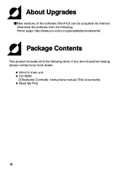
Home page: http://www.jvc-victor.co.jp/english/pro/vnetworks/ Package Contents This product includes all of the software (VN-A1U) can be missing, please contact your local dealer. ● VN-A1U main unit ● CD-ROM {V.Networks Controller, Instructions manual (This document)} ● Read Me First 10 About Upgrades ⅥNew versions of the following . Download the software from the following items. If any item should be acquired via Internet.
Home page: http://www.jvc-victor.co.jp/english/pro/vnetworks/ Package Contents This product includes all of the software (VN-A1U) can be missing, please contact your local dealer. ● VN-A1U main unit ● CD-ROM {V.Networks Controller, Instructions manual (This document)} ● Read Me First 10 About Upgrades ⅥNew versions of the following . Download the software from the following items. If any item should be acquired via Internet.

Instruction Manual
Page 11
... Windows 98, Me, XP Home, NT (Service Pack5 or higher), 2000 Professional (Service Pack1 or higher) or XP Professional. ● CPU ● Memory capacity ● HDD space ● Display and video card ...software requires higher environments than described as operating environmnts for operation of cross cables is not possible with some LAN boards.) ● When used with 100 BASE-TX, please use a CAT-5 cable. 11 LAN environment ● 10BASE-T or 100BASE-TX networks mutually connected by hubs, etc., that conform to IEEE 802.3 or IEEE802.3u. ● The VN-A1U and a PC can be connected...
... Windows 98, Me, XP Home, NT (Service Pack5 or higher), 2000 Professional (Service Pack1 or higher) or XP Professional. ● CPU ● Memory capacity ● HDD space ● Display and video card ...software requires higher environments than described as operating environmnts for operation of cross cables is not possible with some LAN boards.) ● When used with 100 BASE-TX, please use a CAT-5 cable. 11 LAN environment ● 10BASE-T or 100BASE-TX networks mutually connected by hubs, etc., that conform to IEEE 802.3 or IEEE802.3u. ● The VN-A1U and a PC can be connected...
Instruction Manual
Page 13
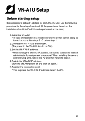
... the setup of installation in the PC. 13 Enable the VN-A1U IP address. (Turn the VN-A1U power off and then on again.) 5.Register the connection point. * This registers the VN-A1U IP address data in a location where the power cannot easily be turned on , the installation of multiple VN-A1U can be performed at one time.) 1.Install the VN-A1U * In case of each VN-A1U unit. Set the VN-A1U IP address. * When setting the VN-A1U IP address, be ON.) 3. Use...
... the setup of installation in the PC. 13 Enable the VN-A1U IP address. (Turn the VN-A1U power off and then on again.) 5.Register the connection point. * This registers the VN-A1U IP address data in a location where the power cannot easily be turned on , the installation of multiple VN-A1U can be performed at one time.) 1.Install the VN-A1U * In case of each VN-A1U unit. Set the VN-A1U IP address. * When setting the VN-A1U IP address, be ON.) 3. Use...
Instruction Manual
Page 14
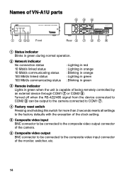
... : Blinking in green 3 Remote indicator Lights in green when the unit is capable of the monitor, switcher, etc. 14 Turned off when the RS-422/485 signal from the device connected to COM2 8 can be output to the camera connected to COM1 7. 4 Factory reset switch Pressing and holding this switch for more than 2 seconds resets all settings to the factory defaults with the exception of the clock setting. 5 Composite video...
... : Blinking in green 3 Remote indicator Lights in green when the unit is capable of the monitor, switcher, etc. 14 Turned off when the RS-422/485 signal from the device connected to COM2 8 can be output to the camera connected to COM1 7. 4 Factory reset switch Pressing and holding this switch for more than 2 seconds resets all settings to the factory defaults with the exception of the clock setting. 5 Composite video...

Instruction Manual
Page 15
.../485 is selected When RS-232C is "RS-232C". ! The factory setting is selected RX+ NC RX- ALARM INPUT/OUTPUT terminals @ Power supply terminals 15 TX- Remotely controlling the externally connected camera is possible using separate software. • Remote mode: Enables the remote control of the externally connected camera with RS-232C. • Through mode: Reception of RS-422/485 control signal from RS-232C and RS422/485. TX+ NC NC...
.../485 is selected When RS-232C is "RS-232C". ! The factory setting is selected RX+ NC RX- ALARM INPUT/OUTPUT terminals @ Power supply terminals 15 TX- Remotely controlling the externally connected camera is possible using separate software. • Remote mode: Enables the remote control of the externally connected camera with RS-232C. • Through mode: Reception of RS-422/485 control signal from RS-232C and RS422/485. TX+ NC NC...
Instruction Manual
Page 16
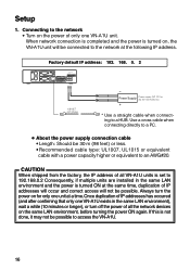
... VN-A1U unit. Factory default IP address: 192. 168. 0. 2 CLASS 2 ONLY FOR USA ISOLATED POWER ONLY FOR EUROPE 10 BASE-T CAT-5 Cable - If this is not done, it may not be 30 m (98 feet) or less. •Recommended cable type: UL1007, UL1015 or equivalent cable with a power capacity higher or equivalent to access the VN-A1U. 16 Use a cross cable when connecting directly to a PC. ● About the power supply connection cable...
... VN-A1U unit. Factory default IP address: 192. 168. 0. 2 CLASS 2 ONLY FOR USA ISOLATED POWER ONLY FOR EUROPE 10 BASE-T CAT-5 Cable - If this is not done, it may not be 30 m (98 feet) or less. •Recommended cable type: UL1007, UL1015 or equivalent cable with a power capacity higher or equivalent to access the VN-A1U. 16 Use a cross cable when connecting directly to a PC. ● About the power supply connection cable...
Instruction Manual
Page 21
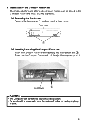
... cover Remove the two screws 1 and remove the front cover. Installation of the Compact Flash Card The images before and after a detection of motion can be purchased separately. • Be sure to set the power switches of the devices off before connecting anything to them. 21 3. To remove the Compact Flash card, pull the eject lever up and push it.
... cover Remove the two screws 1 and remove the front cover. Installation of the Compact Flash Card The images before and after a detection of motion can be purchased separately. • Be sure to set the power switches of the devices off before connecting anything to them. 21 3. To remove the Compact Flash card, pull the eject lever up and push it.
Instruction Manual
Page 23
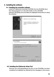
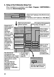
Execute \JVC\Setup.exe and follow the displayed instructions to setup the software. 5-2 Installing the V.Networks Setup Tool Execute the \JVC\setup\Setup.exe file on the CD-ROM, and then complete the installation as directed by the messages on the CD-ROM. Installing the software 5-1 Installing the controller software Load the V.Networks Controller CD-ROM into the CD-ROM drive. The setup program is in the \JVC folder on the screen. 23 5.
Execute \JVC\Setup.exe and follow the displayed instructions to setup the software. 5-2 Installing the V.Networks Setup Tool Execute the \JVC\setup\Setup.exe file on the CD-ROM, and then complete the installation as directed by the messages on the CD-ROM. Installing the software 5-1 Installing the controller software Load the V.Networks Controller CD-ROM into the CD-ROM drive. The setup program is in the \JVC folder on the screen. 23 5.
Instruction Manual
Page 24
... VN-A1U to set . For setting of the V.Networks Setup Tool When installation is used as CAM00001, CAM00002..... If a suitable value is clicked. 24 V.NETWORKS to set up the motion detection operation. Click to invoke the VN-A1U Setup Tool. Setup of the password setup, see page 32. will be set the FTP function. The VN-A1U ID corresponds to display the Compact Flash information. The factory-set IP address is: 192.168.0.2 Change to set the function for recording...
... VN-A1U to set . For setting of the V.Networks Setup Tool When installation is used as CAM00001, CAM00002..... If a suitable value is clicked. 24 V.NETWORKS to set up the motion detection operation. Click to invoke the VN-A1U Setup Tool. Setup of the password setup, see page 32. will be set the FTP function. The VN-A1U ID corresponds to display the Compact Flash information. The factory-set IP address is: 192.168.0.2 Change to set the function for recording...
Instruction Manual
Page 25
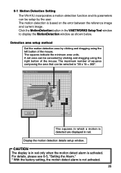
..., please see 6-5, "Setting the Alarm." * With the factory setting, the motion detect alarm is based on the error between the reference image and current image. A set area can be selected is activated. The motion detection is not activated. 25 The maximum number of squares composing the area that can be canceled by clicking and dragging using the left button of the mouse. 6-1 Motion Detection Setting The VN-A1U incorporates a motion detection function and its...
..., please see 6-5, "Setting the Alarm." * With the factory setting, the motion detect alarm is based on the error between the reference image and current image. A set area can be selected is activated. The motion detection is not activated. 25 The maximum number of squares composing the area that can be canceled by clicking and dragging using the left button of the mouse. 6-1 Motion Detection Setting The VN-A1U incorporates a motion detection function and its...
Instruction Manual
Page 28
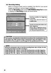
..., CompactFlash records an image for triggering recording. Click the Recording button in the V.NETWORKS Setup Tool window to various trigger conditions. 6-2 Recording Setting When a Compact Flash card is installed, the VN-A1U can record images according to display the Recording window as shown below. Check the desired boxes to record images for the specified period of time. With certain image compression rates and objects, it may sometimes not be possible to enable them. Image size...
..., CompactFlash records an image for triggering recording. Click the Recording button in the V.NETWORKS Setup Tool window to various trigger conditions. 6-2 Recording Setting When a Compact Flash card is installed, the VN-A1U can record images according to display the Recording window as shown below. Check the desired boxes to record images for the specified period of time. With certain image compression rates and objects, it may sometimes not be possible to enable them. Image size...
Instruction Manual
Page 32
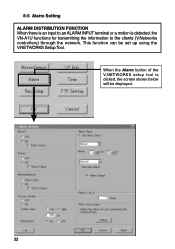
6-5 Alarm Setting ALARM DISTRIBUTION FUNCTION When there is an input to an ALARM INPUT terminal or a motion is clicked, the screen shown below will be set up using the V.NETWORKS Setup Tool. When the Alarm button of the V.NETWORKS setup tool is detected, the VN-A1U functions for transmitting the information to the clients (V.Networks controllers) through the network. This function can be displayed. 32
6-5 Alarm Setting ALARM DISTRIBUTION FUNCTION When there is an input to an ALARM INPUT terminal or a motion is clicked, the screen shown below will be set up using the V.NETWORKS Setup Tool. When the Alarm button of the V.NETWORKS setup tool is detected, the VN-A1U functions for transmitting the information to the clients (V.Networks controllers) through the network. This function can be displayed. 32

Instruction Manual
Page 33
... case of relay alarm. Example: If relay alarm is set an alarm or motion detection input received after an Alarm 1, Alarm 2 or motion detection input has been received, to be executed. 33 The operation of Alarm 2 itself will not activate. Check Use Relay Alarm and specify the alarm occurrence sequence and the time interval between alarms. If the alarm signal is selected, also check the Alarm Output if the alarm signal should be...
... case of relay alarm. Example: If relay alarm is set an alarm or motion detection input received after an Alarm 1, Alarm 2 or motion detection input has been received, to be executed. 33 The operation of Alarm 2 itself will not activate. Check Use Relay Alarm and specify the alarm occurrence sequence and the time interval between alarms. If the alarm signal is selected, also check the Alarm Output if the alarm signal should be...

Instruction Manual
Page 36
... nothing is displayed by clicking the User, Operator or Administrator button on the Password Setting screen of Access Rights Can view the images. To set . (Password level: User < Operator < Administrator) If the Administrator password does not match, it matches the password setting. Password setting and cancellation is provided to perform the VN-A1U setup.A password will be requested when the lower level password(s) has been set but the higher has not been set password protection or change will...
... nothing is displayed by clicking the User, Operator or Administrator button on the Password Setting screen of Access Rights Can view the images. To set . (Password level: User < Operator < Administrator) If the Administrator password does not match, it matches the password setting. Password setting and cancellation is provided to perform the VN-A1U setup.A password will be requested when the lower level password(s) has been set but the higher has not been set password protection or change will...

Instruction Manual
Page 37
... be set IP address valid When the IP address is changed, the pan and tilt mechanism will work and the IP address becomes valid after the VN-A1U is reset. 6-8 Special Notes on the V.NETWORKS Setup Tool CAUTION The V.NETWORKS Setup Tool is software that you made a note and then restore a work PC IP address Using the same procedure as in 4-1, select Settings from the Start button, then select Control Panel and Network, Change to...
... be set IP address valid When the IP address is changed, the pan and tilt mechanism will work and the IP address becomes valid after the VN-A1U is reset. 6-8 Special Notes on the V.NETWORKS Setup Tool CAUTION The V.NETWORKS Setup Tool is software that you made a note and then restore a work PC IP address Using the same procedure as in 4-1, select Settings from the Start button, then select Control Panel and Network, Change to...

Instruction Manual
Page 38
... of the VN-A1U connection point. (192.168.0.2 is used as an example in the folder specified here. Click OK to page 53 recording function.) "Start recording on connection" determines whether or not recording will be saved here. (Refer to complete the registration. 38 Clicking the OK button displays the setting confirmation screen. Registering connection points Start the V.Networks controller (VN-A1U connection software: vn-a1u.exe), open the File menu, select...
... of the VN-A1U connection point. (192.168.0.2 is used as an example in the folder specified here. Click OK to page 53 recording function.) "Start recording on connection" determines whether or not recording will be saved here. (Refer to complete the registration. 38 Clicking the OK button displays the setting confirmation screen. Registering connection points Start the V.Networks controller (VN-A1U connection software: vn-a1u.exe), open the File menu, select...
Instruction Manual
Page 41
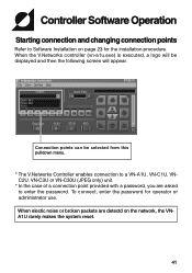
... to Software Installation on the network, the VNA1U rarely makes the system reset. 41 Connection points can be displayed and then the following screen will be selected from this pulldown menu. * The V.Networks Controller enables connection to a VN-A1U, VN-C1U, VNC2U, VN-C3U or VN-C30U (JPEG only) unit. * In the case of a connection point provided with a password, you are detectd on page 23 for operator or administrator use. When the V.Networks controller (vn-a1u...
... to Software Installation on the network, the VNA1U rarely makes the system reset. 41 Connection points can be displayed and then the following screen will be selected from this pulldown menu. * The V.Networks Controller enables connection to a VN-A1U, VN-C1U, VNC2U, VN-C3U or VN-C30U (JPEG only) unit. * In the case of a connection point provided with a password, you are detectd on page 23 for operator or administrator use. When the V.Networks controller (vn-a1u...

Instruction Manual
Page 48
... Properties displays the MAC address, IP address, unit name, program version, and storage destination. Display the motion detection information. Click the right button of the mouse on the screen and select one of the following procedure. Changing resolution and inverting the image Select View from 160 x 120, 320 x 240 or 640 x 480. The resolution can also be selected from the menu. When checked: The area where motion is detected is displayed in colors...
... Properties displays the MAC address, IP address, unit name, program version, and storage destination. Display the motion detection information. Click the right button of the mouse on the screen and select one of the following procedure. Changing resolution and inverting the image Select View from 160 x 120, 320 x 240 or 640 x 480. The resolution can also be selected from the menu. When checked: The area where motion is detected is displayed in colors...


