
Instruction Manual
Page 5
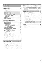
... V power supply 15 LAN Cable Connection 16 Monitor Signal Output Terminal Connection 16 Alarm Input/Output Terminal Connection 17 Alarm Input Terminal 17 Alarm Output Terminal 17 Mounting the Camera 18 Mounting to the Housing Using the Inner Tripod Base 19 Back Focus Adjustment 20 Network Requirements 21 Network Settings 23 IP Address Settings 23 Setting the IP address for VN-V25U ..... 23 When the IP address of VN-V25U is known 28 When the IP address of VN-V25U is unknown 28 Setting Using Internet Explorer ......29 Setup 29 Internet Explorer Setup 29 Setting...
... V power supply 15 LAN Cable Connection 16 Monitor Signal Output Terminal Connection 16 Alarm Input/Output Terminal Connection 17 Alarm Input Terminal 17 Alarm Output Terminal 17 Mounting the Camera 18 Mounting to the Housing Using the Inner Tripod Base 19 Back Focus Adjustment 20 Network Requirements 21 Network Settings 23 IP Address Settings 23 Setting the IP address for VN-V25U ..... 23 When the IP address of VN-V25U is known 28 When the IP address of VN-V25U is unknown 28 Setting Using Internet Explorer ......29 Setup 29 Internet Explorer Setup 29 Setting...
Instruction Manual
Page 6
... this manual are subject to changes for adjusting the camera angle during surveillance at a rate of 30 fps. Ⅵ Support for Multicast This product supports multicast, which switches automatically to the high sensitivity mode (black-and-white). Ⅵ Privacy Mask You can configure the privacy mask setting to hide specific area in shooting area. Ⅵ Motion Detection This feature enables output of an alarm upon detection of image data to use...
... this manual are subject to changes for adjusting the camera angle during surveillance at a rate of 30 fps. Ⅵ Support for Multicast This product supports multicast, which switches automatically to the high sensitivity mode (black-and-white). Ⅵ Privacy Mask You can configure the privacy mask setting to hide specific area in shooting area. Ⅵ Motion Detection This feature enables output of an alarm upon detection of image data to use...

Instruction Manual
Page 7
..., TV, transformer, monitor, etc.) may trap heat, such as near walls. Make sure that may cause noise interferences in the images or changes in the color. ⅷ Do not install this product at locations that you use a housing when using devices such as kitchens. ● Locations that emit radiation, X-rays or corrosive gases. ⅷ Use of the camera unit. As such, do...
..., TV, transformer, monitor, etc.) may trap heat, such as near walls. Make sure that may cause noise interferences in the images or changes in the color. ⅷ Do not install this product at locations that you use a housing when using devices such as kitchens. ● Locations that emit radiation, X-rays or corrosive gases. ⅷ Use of the camera unit. As such, do...
Instruction Manual
Page 8
... white balance circuit. When using copyrighted video/ audio data, be easily removed, wipe using a neutral detergent diluted with water, followed by wiping with regard to the invasion of privacy by default. JVC shall not be liable for shooting or using this camera. Viewing of multicast images on of the air conditioner's power, the image may occur. ⅷ When using the PoE or connecting the AC 24 V power supply...
... white balance circuit. When using copyrighted video/ audio data, be easily removed, wipe using a neutral detergent diluted with water, followed by wiping with regard to the invasion of privacy by default. JVC shall not be liable for shooting or using this camera. Viewing of multicast images on of the air conditioner's power, the image may occur. ⅷ When using the PoE or connecting the AC 24 V power supply...

Instruction Manual
Page 10
... signal system. This product supports PoE (IEEE802.3af class 2) and therefore can adjust the [LED State] settings via a LAN cable. NTSC : Outputs NTSC signals. Do not press the button for rebooting the camera. Use this terminal to connect to mount the fall prevention wire. (A Page 18) K [RESET] Reset Button This is disabled. Note: Pressing the [RESET] button for composite video signals (1 V (p-p), output impedance of output from the N [MONITOR OUT] terminal as well...
... signal system. This product supports PoE (IEEE802.3af class 2) and therefore can adjust the [LED State] settings via a LAN cable. NTSC : Outputs NTSC signals. Do not press the button for rebooting the camera. Use this terminal to connect to mount the fall prevention wire. (A Page 18) K [RESET] Reset Button This is disabled. Note: Pressing the [RESET] button for composite video signals (1 V (p-p), output impedance of output from the N [MONITOR OUT] terminal as well...
Instruction Manual
Page 12
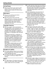
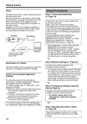
... changing the [MONITOR OUT] switch setting, press the Reset button to monitor JPEG and MPEG4 images and save JPEG images. Getting Started Alarm VN-V25U comes with a motion detection feature and dual alarm input. These actions can also be triggered. For details, please refer to AAPI GuideB in viewers enable you to reboot the camera. Images are used, turn on the computer. 12 Setup Procedures Step 1 Connection/Installation (A Page 14) Connect the lens mount, power supply cord, LAN cable and alarm. Configure...
... changing the [MONITOR OUT] switch setting, press the Reset button to monitor JPEG and MPEG4 images and save JPEG images. Getting Started Alarm VN-V25U comes with a motion detection feature and dual alarm input. These actions can also be triggered. For details, please refer to AAPI GuideB in viewers enable you to reboot the camera. Images are used, turn on the computer. 12 Setup Procedures Step 1 Connection/Installation (A Page 14) Connect the lens mount, power supply cord, LAN cable and alarm. Configure...
Instruction Manual
Page 14
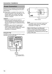
... is PoE (Power over Ethernet)? OUTPUT INPUT CLASS 2 ONLY FOR USA ISOLATED POWER ONLY FOR EUROPE AND OTHER AC24V ALARM PoE MONITOR OUT 10BASE-T/ SEE INSTRUCTION MANUAL 100BASE-TX CAUTION: NEVER USE PoE AND AC 24V AT THE SAME TIME DO NOT CONNECT TO THE TELEPHONE NETWORK PUSH Connect to malfunction or breakdown. Using the PoE Connect to a device that supports PoE to supply electricity from the primary power supply circuit. The indicator lights...
... is PoE (Power over Ethernet)? OUTPUT INPUT CLASS 2 ONLY FOR USA ISOLATED POWER ONLY FOR EUROPE AND OTHER AC24V ALARM PoE MONITOR OUT 10BASE-T/ SEE INSTRUCTION MANUAL 100BASE-TX CAUTION: NEVER USE PoE AND AC 24V AT THE SAME TIME DO NOT CONNECT TO THE TELEPHONE NETWORK PUSH Connect to malfunction or breakdown. Using the PoE Connect to a device that supports PoE to supply electricity from the primary power supply circuit. The indicator lights...

Instruction Manual
Page 15
... address of cords, use it with the correct voltage. Otherwise, access to VN-V25U may result in failures, smoke or fire. To Power Supply OUTPUT CLASS 2 ONLY FOR USA ISOLATED POWER ONLY FOR EUROPE AND OTHER 1 2 G2 12 1 INPUT AC24V ALARM PoE MONITOR OUT 10BASE-T/ SEE INSTRUCTION MANUAL 100BASE-TX CAUTION: NEVER USE PoE AND AC 24V AT THE SAME TIME DO NOT CONNECT TO THE TELEPHONE NETWORK PUSH MONITOR...
... address of cords, use it with the correct voltage. Otherwise, access to VN-V25U may result in failures, smoke or fire. To Power Supply OUTPUT CLASS 2 ONLY FOR USA ISOLATED POWER ONLY FOR EUROPE AND OTHER 1 2 G2 12 1 INPUT AC24V ALARM PoE MONITOR OUT 10BASE-T/ SEE INSTRUCTION MANUAL 100BASE-TX CAUTION: NEVER USE PoE AND AC 24V AT THE SAME TIME DO NOT CONNECT TO THE TELEPHONE NETWORK PUSH MONITOR...
Instruction Manual
Page 17
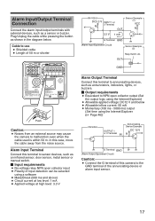
... FOR USA ISOLATED POWER ONLY FOR EUROPE AND OTHER AC24V ALARM PoE MONITOR OUT 10BASE-T/ SEE INSTRUCTION MANUAL 100BASE-TX CAUTION: NEVER USE PoE AND AC 24V AT THE SAME TIME DO NOT CONNECT TO THE TELEPHONE NETWORK PUSH Push Caution: ● Noises from the noise source. Plug/Unplug the cable while pressing the button as annunciators, indicators, lights, or buzzers. Ⅵ Output requirements ● Equivalent...
... FOR USA ISOLATED POWER ONLY FOR EUROPE AND OTHER AC24V ALARM PoE MONITOR OUT 10BASE-T/ SEE INSTRUCTION MANUAL 100BASE-TX CAUTION: NEVER USE PoE AND AC 24V AT THE SAME TIME DO NOT CONNECT TO THE TELEPHONE NETWORK PUSH Push Caution: ● Noises from the noise source. Plug/Unplug the cable while pressing the button as annunciators, indicators, lights, or buzzers. Ⅵ Output requirements ● Equivalent...
Instruction Manual
Page 18
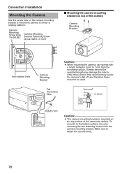
.... 18 Camera Mounting Screw Hole 1/4-20UNC Camera Mounting Bracket Fastening Screw (2 pcs: M2.6 x 6 mm) Ⅵ Mounting the camera mounting bracket on top of the camera by removing the two fastening screws from the mounting surface. Connection / Installation Mounting the Camera Use the screw hole on the camera mounting bracket to mount this camera to fall off, and therefore these must not be used. Make sure to the bottom surface, do so by default.
.... 18 Camera Mounting Screw Hole 1/4-20UNC Camera Mounting Bracket Fastening Screw (2 pcs: M2.6 x 6 mm) Ⅵ Mounting the camera mounting bracket on top of the camera by removing the two fastening screws from the mounting surface. Connection / Installation Mounting the Camera Use the screw hole on the camera mounting bracket to mount this camera to fall off, and therefore these must not be used. Make sure to the bottom surface, do so by default.
Instruction Manual
Page 25
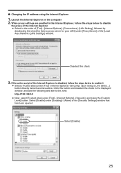
... in the order of [Tool]-[Internet Options]-[Connections]-[LAN Setting], followed by deselecting the check for [Use a proxy server for your LAN] under [Tool]-[Internet Options]-[Security], and press the [Custom Level] button. ⅷ Changing the IP address using the Internet Explorer 1. Deselect the check 3. When proxy settings are enabled in the Internet Explorer, follow the steps below to disable the proxy of the [Local Area Network (LAN) Settings] window.
... in the order of [Tool]-[Internet Options]-[Connections]-[LAN Setting], followed by deselecting the check for [Use a proxy server for your LAN] under [Tool]-[Internet Options]-[Security], and press the [Custom Level] button. ⅷ Changing the IP address using the Internet Explorer 1. Deselect the check 3. When proxy settings are enabled in the Internet Explorer, follow the steps below to disable the proxy of the [Local Area Network (LAN) Settings] window.

Instruction Manual
Page 30
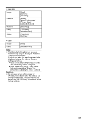
... Connection of the user. ● admin Image [View] [Camera] [Encoding] External [Alarm] [Alarm Environment] [Privacy Mask] [Motion Detection] Network [Basic] [Details] [Protocol] [Streaming] [Access Restrictions] [Time] [Password] Utility [Maintenance] [LED State] [Miscellaneous] Status [Operation] [Settings] 30 In the opened window, add the address of images is set the pop-up block to the access authority of VN-V25U cannot be required at the beginning. In addition, links on the pages that users have access to network and maintenance are allowed Viewing of VN-V25U...
... Connection of the user. ● admin Image [View] [Camera] [Encoding] External [Alarm] [Alarm Environment] [Privacy Mask] [Motion Detection] Network [Basic] [Details] [Protocol] [Streaming] [Access Restrictions] [Time] [Password] Utility [Maintenance] [LED State] [Miscellaneous] Status [Operation] [Settings] 30 In the opened window, add the address of images is set the pop-up block to the access authority of VN-V25U cannot be required at the beginning. In addition, links on the pages that users have access to network and maintenance are allowed Viewing of VN-V25U...
Instruction Manual
Page 31
... content]. ● operator Image External Network Utility Status [View] [Camera] [Encoding] [Alarm] [Alarm Environment] [Privacy Mask] [Motion Detection] [Streaming] [LED State] [Miscellaneous] [Operation] [Settings] ● user Image Utility [View] [Miscellaneous] Note: ● The [Security Settings] screen appears before the top page is displayed. Caution: ● Do not reset or turn off the power of VN-V25U immediately after the settings are changed. If you do not want this warning screen to the factory settings. 31 Press the [Yes] button to proceed.
... content]. ● operator Image External Network Utility Status [View] [Camera] [Encoding] [Alarm] [Alarm Environment] [Privacy Mask] [Motion Detection] [Streaming] [LED State] [Miscellaneous] [Operation] [Settings] ● user Image Utility [View] [Miscellaneous] Note: ● The [Security Settings] screen appears before the top page is displayed. Caution: ● Do not reset or turn off the power of VN-V25U immediately after the settings are changed. If you do not want this warning screen to the factory settings. 31 Press the [Yes] button to proceed.

Instruction Manual
Page 67
... Destination Port 49152 JPEG Frame Rate 15 fps MPEG4 Destination Address 225.0.2.1 MPEG4 Destination Port 59152 Ⅵ Access Restrictions Page Item Factory Settings Access Restrictions deny IP Address - Ⅵ Time Page Item SNTP NTP Server Access Interval Time Zone Factory Settings Off 0.0.0.0 hour, 1 (GMT) UTC Ⅵ Password Page Item Factory Settings Username Current Password AadminB Blank Default passwords are: AadminB : vn-v2x AoperatorB : vn-v2x AuserB : vn-v2x Ⅵ LED Settings Page Item Factory Settings LED State Enable Identify Unit On...
... Destination Port 49152 JPEG Frame Rate 15 fps MPEG4 Destination Address 225.0.2.1 MPEG4 Destination Port 59152 Ⅵ Access Restrictions Page Item Factory Settings Access Restrictions deny IP Address - Ⅵ Time Page Item SNTP NTP Server Access Interval Time Zone Factory Settings Off 0.0.0.0 hour, 1 (GMT) UTC Ⅵ Password Page Item Factory Settings Username Current Password AadminB Blank Default passwords are: AadminB : vn-v2x AoperatorB : vn-v2x AuserB : vn-v2x Ⅵ LED Settings Page Item Factory Settings LED State Enable Identify Unit On...
Startup Guide
Page 5
... Connection 16 Alarm Input/Output Terminal Connection 17 Alarm Input Terminal 17 Alarm Output Terminal 17 Mounting the Camera 18 Mounting to the Housing Using the Inner Tripod Base 19 Back Focus Adjustment 20 Network Requirements 21 Network Settings 23 IP Address Settings 23 Setting the IP address for Built-in the supplied CD-ROM. Operation 29 Operation of Built-in Viewer 29 Internet Explorer Setup 30 Installing the built-in viewer 32 Screen Configuration of JPEG Viewer 33 Exiting the JPEG Viewer 34 Screen Configuration of VN-V25U...
... Connection 16 Alarm Input/Output Terminal Connection 17 Alarm Input Terminal 17 Alarm Output Terminal 17 Mounting the Camera 18 Mounting to the Housing Using the Inner Tripod Base 19 Back Focus Adjustment 20 Network Requirements 21 Network Settings 23 IP Address Settings 23 Setting the IP address for Built-in the supplied CD-ROM. Operation 29 Operation of Built-in Viewer 29 Internet Explorer Setup 30 Installing the built-in viewer 32 Screen Configuration of JPEG Viewer 33 Exiting the JPEG Viewer 34 Screen Configuration of VN-V25U...

Startup Guide
Page 6
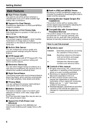
... of this manual are subject to changes for improvement without lowering the frame rate. Ⅵ Built-in Web Server You can configure the picture quality and communication settings using the alarm input. Ⅵ Support for PoE (Power over Ethernet) This product supports PoE (IEEE802.3af class 2) and enables power supply from a LAN cable. Ⅵ Built-in JPEG and MPEG4 Viewer Monitoring of JPEG and MPEG4 images via the network. Ⅵ Electronic...
... of this manual are subject to changes for improvement without lowering the frame rate. Ⅵ Built-in Web Server You can configure the picture quality and communication settings using the alarm input. Ⅵ Support for PoE (Power over Ethernet) This product supports PoE (IEEE802.3af class 2) and enables power supply from a LAN cable. Ⅵ Built-in JPEG and MPEG4 Viewer Monitoring of JPEG and MPEG4 images via the network. Ⅵ Electronic...
Startup Guide
Page 7
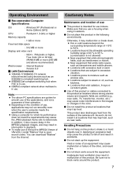
... radiation, X-rays or corrosive gases. ⅷ Use of use indoors. Operating Environment Ⅵ Recommended Computer Specifications OS : Windows XP (Professional or Home Edition) (SP2) CPU : Pentium4 1.5 GHz or higher Memory capacity : 1 GB or more Free hard disk space : 512 MB or more Display and video card : 1024 ן768 pixels or higher, True Color (24 or 32 bits) VRAM 8 MB...
... radiation, X-rays or corrosive gases. ⅷ Use of use indoors. Operating Environment Ⅵ Recommended Computer Specifications OS : Windows XP (Professional or Home Edition) (SP2) CPU : Pentium4 1.5 GHz or higher Memory capacity : 1 GB or more Free hard disk space : 512 MB or more Display and video card : 1024 ן768 pixels or higher, True Color (24 or 32 bits) VRAM 8 MB...
Startup Guide
Page 10
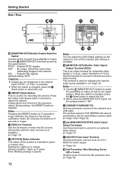
... a video monitor. During startup, the [RESET] button is changed , press the K Reset button to mount the fall prevention wire. (A Page 18) Starting up: Lights up in orange Startup complete: Lights up in green or orange color. PAL : Outputs PAL signals. [Default setting: OFF] Caution: ● Images are not distributed to the network when ANTSCB or APALB is selected. ● When the switch is an output terminal for adjusting the camera angle...
... a video monitor. During startup, the [RESET] button is changed , press the K Reset button to mount the fall prevention wire. (A Page 18) Starting up: Lights up in orange Startup complete: Lights up in green or orange color. PAL : Outputs PAL signals. [Default setting: OFF] Caution: ● Images are not distributed to the network when ANTSCB or APALB is selected. ● When the switch is an output terminal for adjusting the camera angle...
Startup Guide
Page 12
... unit to the server. Remember also to the network when ANTSCB or APALB is mounted, connect the video monitor to the [MONITOR OUT] terminal at the same time records images to "Instructions" (pdf) in viewers enable you to reboot the camera. Images are used, turn on the computer. G Step 2 Network settings (A Page 23) Configure the network settings of images by combination of alarm occurrence on the power of the [MONITOR OUT] terminal using the [MONITOR OUT] switch. (ANTSCB or APALB) (Back focus adjustment...
... unit to the server. Remember also to the network when ANTSCB or APALB is mounted, connect the video monitor to the [MONITOR OUT] terminal at the same time records images to "Instructions" (pdf) in viewers enable you to reboot the camera. Images are used, turn on the computer. G Step 2 Network settings (A Page 23) Configure the network settings of images by combination of alarm occurrence on the power of the [MONITOR OUT] terminal using the [MONITOR OUT] switch. (ANTSCB or APALB) (Back focus adjustment...

Startup Guide
Page 15
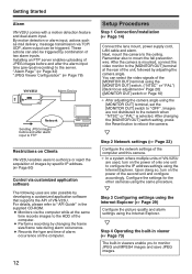
...; In a system where multiple units of VN-V25U are turned on the appearance and operation of cords, use it with the correct voltage. Configure the camera settings using the Internet Explorer. Otherwise, access to VN-V25U may be powered by an AC 24 V power supply. When a power beyond the rated value may result in failures, smoke or fire. Note: ● After DHCP timeout, all network devices under the same LAN...
...; In a system where multiple units of VN-V25U are turned on the appearance and operation of cords, use it with the correct voltage. Configure the camera settings using the Internet Explorer. Otherwise, access to VN-V25U may be powered by an AC 24 V power supply. When a power beyond the rated value may result in failures, smoke or fire. Note: ● After DHCP timeout, all network devices under the same LAN...


