
GY-DV500 User Manual - PDF (4,089KB)
Page 20
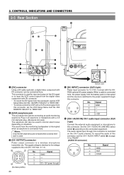
... Signal 1 GND 2 - 3 - 4 DC +12V (power through this connector. The sound from the battery pack is interrupted and the source is a stereo mini-jack for connecting an audio monitoring earphone. No. Signal 1 4 1 GND 2 - 23 3 - 4 +12V 5 [CH-1 AUDIO IN] CH-1 audio ...wireless microphone transmitter, etc. This connector is used for 12 V DC. 2. CONTROLS, INDICATORS AND CONNECTORS 2-5 Rear Section !1 PUSH 0 DV CAMCORDER GY-DV500 q w e EARPHONE DV CH-1 AUDIO IN CH-2 LINE MIC LINE MIC DC INPUT +48V ON +48V ON TALLY DC OUTPUT i o u Y/C OUT MONITOR...
... Signal 1 GND 2 - 3 - 4 DC +12V (power through this connector. The sound from the battery pack is interrupted and the source is a stereo mini-jack for connecting an audio monitoring earphone. No. Signal 1 4 1 GND 2 - 23 3 - 4 +12V 5 [CH-1 AUDIO IN] CH-1 audio ...wireless microphone transmitter, etc. This connector is used for 12 V DC. 2. CONTROLS, INDICATORS AND CONNECTORS 2-5 Rear Section !1 PUSH 0 DV CAMCORDER GY-DV500 q w e EARPHONE DV CH-1 AUDIO IN CH-2 LINE MIC LINE MIC DC INPUT +48V ON +48V ON TALLY DC OUTPUT i o u Y/C OUT MONITOR...


