

Instruction Manual
Page 3
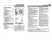
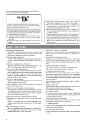
...remaining time, remaining battery power, audio levels, VCR section setup menus, hour meter data, and a variety of copyright holders. ● JVC cannot assume liabilities ...Maintenance 8 1-4 Videocassette to be Used 8 1-5 Battery Pack to be used with shooting conditions which are for purchasing the DV Camcorder GY-DV500. The display is ideal for difficult shooting conditions... illumination Employment of the S.S.F. Eliminates flicker when shooting other screen pictures than PAL, such as computer monitor screens. Eliminates flicker when shooting other screen pictures than...
...remaining time, remaining battery power, audio levels, VCR section setup menus, hour meter data, and a variety of copyright holders. ● JVC cannot assume liabilities ...Maintenance 8 1-4 Videocassette to be Used 8 1-5 Battery Pack to be used with shooting conditions which are for purchasing the DV Camcorder GY-DV500. The display is ideal for difficult shooting conditions... illumination Employment of the S.S.F. Eliminates flicker when shooting other screen pictures than PAL, such as computer monitor screens. Eliminates flicker when shooting other screen pictures than...
Instruction Manual
Page 4
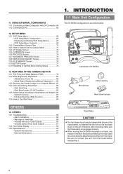
...TC UB Camcorder (GY-DV500) Microphone CR230V32 Lithium battery Head ... If a tape containing recorded PAL signals is not to be...GY-DV500 for long hours in an upright position. In addition, salt and sand may occur at your nearest JVC...GY-DV500 automatically enters the STOP mode. Depending on a Computer Monitor 81 13-4 Gain (Sensitivity) Adjustment 82 • Gain Switching 82 • Gain Boost under direct sunlight or near room heating equipment. ● Protect the unit from the factory. To prevent deformation of professional...level is provided with DV Connector 64 11-2 ...
...TC UB Camcorder (GY-DV500) Microphone CR230V32 Lithium battery Head ... If a tape containing recorded PAL signals is not to be...GY-DV500 for long hours in an upright position. In addition, salt and sand may occur at your nearest JVC...GY-DV500 automatically enters the STOP mode. Depending on a Computer Monitor 81 13-4 Gain (Sensitivity) Adjustment 82 • Gain Switching 82 • Gain Boost under direct sunlight or near room heating equipment. ● Protect the unit from the factory. To prevent deformation of professional...level is provided with DV Connector 64 11-2 ...

Instruction Manual
Page 5
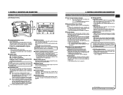
... to the head drum or tape guides and be cooled into storage. ● Store videocassettes in this unit is the expansion of professional video equipment at your nearest JVC-authorized service agent. CH 1 OVER 40 30 20 10 0 dB CH 2 OVER RF 32k 48k AUD LOCK SP MENU "HEAD..."2.4.3 Cleaning". When this occurs, the head drum and tape guides are provided with unevenly wound tape, as this service manual. 1-5 Battery Pack to be Used The GY-DV500 can use any of the VCR section especially during playback and recording check using a head cleaning tape as possible, use the unit ...
... to the head drum or tape guides and be cooled into storage. ● Store videocassettes in this unit is the expansion of professional video equipment at your nearest JVC-authorized service agent. CH 1 OVER 40 30 20 10 0 dB CH 2 OVER RF 32k 48k AUD LOCK SP MENU "HEAD..."2.4.3 Cleaning". When this occurs, the head drum and tape guides are provided with unevenly wound tape, as this service manual. 1-5 Battery Pack to be Used The GY-DV500 can use any of the VCR section especially during playback and recording check using a head cleaning tape as possible, use the unit ...
Instruction Manual
Page 9
... bit. The display mode can be preset while this switch at OFF during battery operation of the CH-1 and CH-2 channels in case of trouble with the 4 COUNTER switch. • Displays the VCR setup menu data when the GY-DV500 is lit. See "Counter Display Contents" on page 56. ^ Warning indicators ...condensation occurs. For instructions on page 69. 16 5 Audio level meters Show the audio input level of the GY-DV500 or when it is set the VCR Setup Menu item No. 396 BATTERY TYPE according to SAVE mode, the illumination will go out even if the backlight is lit. The displayed ...
... bit. The display mode can be preset while this switch at OFF during battery operation of the CH-1 and CH-2 channels in case of trouble with the 4 COUNTER switch. • Displays the VCR setup menu data when the GY-DV500 is lit. See "Counter Display Contents" on page 56. ^ Warning indicators ...condensation occurs. For instructions on page 69. 16 5 Audio level meters Show the audio input level of the GY-DV500 or when it is set the VCR Setup Menu item No. 396 BATTERY TYPE according to SAVE mode, the illumination will go out even if the backlight is lit. The displayed ...

Instruction Manual
Page 11
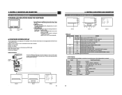
... See the service manual page 1-1 "RESETTING THE POWER CIRCUIT PROTECTION BREAKER". 21 ← CONTROLS, INDICATORS AND CONNECTORS 2-5 Rear Section !1 PUSH 0 DV CAMCORDER GY-DV500 q w e EARPHONE DV CH-1 AUDIO IN CH-2 LINE MIC LINE MIC DC INPUT +48V ON +48V ON TALLY DC OUTPUT i o u Y/C OUT MONITOR OUT LINE...monitor alarm tones depending on page 14 to "IEEE1394". To record the audio of professional video equipment at your nearest JVC-authorized service agent. 0 Battery holder Mount a Flat Shape type battery pack here. The reference input level is -60 dBs. Press the knob to ...
... See the service manual page 1-1 "RESETTING THE POWER CIRCUIT PROTECTION BREAKER". 21 ← CONTROLS, INDICATORS AND CONNECTORS 2-5 Rear Section !1 PUSH 0 DV CAMCORDER GY-DV500 q w e EARPHONE DV CH-1 AUDIO IN CH-2 LINE MIC LINE MIC DC INPUT +48V ON +48V ON TALLY DC OUTPUT i o u Y/C OUT MONITOR OUT LINE...monitor alarm tones depending on page 14 to "IEEE1394". To record the audio of professional video equipment at your nearest JVC-authorized service agent. 0 Battery holder Mount a Flat Shape type battery pack here. The reference input level is -60 dBs. Press the knob to ...
Instruction Manual
Page 14
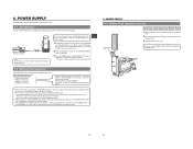
Blinks green : • While the GY-DV500 switches from record- FOCUS G F I ME A A 3 . 2K 1 / 1000 6dB NORMA L NORMA L OF F One of the camera or the VCR. ● [BATT] battery lamp This lights red when the battery voltage becomes too low for use in checking the current camera settings) Alarm message display Safety zone display Setting screen... VIEWFINDER BATT BATT Lamp REC ALARM REC/ALARM Lamp The viewfinder has two LED indicators below the screen. CONTROLS, INDICATORS AND CONNECTORS 2-9 Indications in the GY-DV500. 2.
Blinks green : • While the GY-DV500 switches from record- FOCUS G F I ME A A 3 . 2K 1 / 1000 6dB NORMA L NORMA L OF F One of the camera or the VCR. ● [BATT] battery lamp This lights red when the battery voltage becomes too low for use in checking the current camera settings) Alarm message display Safety zone display Setting screen... VIEWFINDER BATT BATT Lamp REC ALARM REC/ALARM Lamp The viewfinder has two LED indicators below the screen. CONTROLS, INDICATORS AND CONNECTORS 2-9 Indications in the GY-DV500. 2.

Instruction Manual
Page 16
...-1B TYPE BATTERY NP-1B TYPE BATTERY CHARGER 1.5" VIEW FINDER VF-P115B/115/116 ZOOM LENS S14 x 7.3B12(FUJINON) S16 x 6.7B12(FUJINON) S19 x 6.5B12(FUJINON) YH14 x 7.3K12(CANON) YH18 x 6.7K12(CANON) MACRO DVC CAMCORDER MICROPHONE FILTER 1 3200k 2 5600k 3 5600k+ND SHUTTER STATUS MENU ALARM MONITOR AUTO IRIS FULL ...OFF COUNTER CTL TC UB GY-DV500 STANDARD PACKAGE TRIPOD BASE KA-510 FOCUS MANUAL UNIT HZ-FM13 (FUJINON) HZ-FM15 (CANON) ZOOM SERVO UNIT HZ-ZS13B TRIPOD TP-P300 DOLLY TP-P205 CARRYING CASE BATTERY HOLDER BH-P27 BATTERY NB-G1 NB-G1 (4PACK) BATTERY CHARGER (AC POWER ADAPTER) ...
...-1B TYPE BATTERY NP-1B TYPE BATTERY CHARGER 1.5" VIEW FINDER VF-P115B/115/116 ZOOM LENS S14 x 7.3B12(FUJINON) S16 x 6.7B12(FUJINON) S19 x 6.5B12(FUJINON) YH14 x 7.3K12(CANON) YH18 x 6.7K12(CANON) MACRO DVC CAMCORDER MICROPHONE FILTER 1 3200k 2 5600k 3 5600k+ND SHUTTER STATUS MENU ALARM MONITOR AUTO IRIS FULL ...OFF COUNTER CTL TC UB GY-DV500 STANDARD PACKAGE TRIPOD BASE KA-510 FOCUS MANUAL UNIT HZ-FM13 (FUJINON) HZ-FM15 (CANON) ZOOM SERVO UNIT HZ-ZS13B TRIPOD TP-P300 DOLLY TP-P205 CARRYING CASE BATTERY HOLDER BH-P27 BATTERY NB-G1 NB-G1 (4PACK) BATTERY CHARGER (AC POWER ADAPTER) ...

Instruction Manual
Page 18
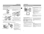
... as illustrated and remove the cover. 2. Front mount clip Pin 4. BASIC SYSTEM CONNECTIONS AND ADJUSTMENTS 3-7 Inserting and Replacing Backup Lithium Batteries The GY-DV500 uses a lithium battery for a lengthy period of the lithium battery at the place indicated in the unit. Therefore, after mounting, make sure that these parts are engaged properly. • When moving...
... as illustrated and remove the cover. 2. Front mount clip Pin 4. BASIC SYSTEM CONNECTIONS AND ADJUSTMENTS 3-7 Inserting and Replacing Backup Lithium Batteries The GY-DV500 uses a lithium battery for a lengthy period of the lithium battery at the place indicated in the unit. Therefore, after mounting, make sure that these parts are engaged properly. • When moving...
Instruction Manual
Page 19
... DV CH-1 AUDIO IN CH-2 LINE MIC LINE MIC DC INPUT +48V ON +48V ON TALLY DC OUTPUT Note: Do not remove or connect the DC cable while recording is set the CHARGE/CAMERA switch to the GY-DV500. When the AA-P250 is disconnected. • Noise to OFF. Battery holder...supply or battery pack. 4-1 AC Operation Use the JVC AA-P250 AC power adapter (max. Do not use any power source with its electrodes facing the unit. 3. Close the battery case cover. POWER SUPPLY The GY-DV500 is necessary to the DC INPUT connector of the GY-DV500 to OFF before replacing the battery pack. ...
... DV CH-1 AUDIO IN CH-2 LINE MIC LINE MIC DC INPUT +48V ON +48V ON TALLY DC OUTPUT Note: Do not remove or connect the DC cable while recording is set the CHARGE/CAMERA switch to the GY-DV500. When the AA-P250 is disconnected. • Noise to OFF. Battery holder...supply or battery pack. 4-1 AC Operation Use the JVC AA-P250 AC power adapter (max. Do not use any power source with its electrodes facing the unit. 3. Close the battery case cover. POWER SUPPLY The GY-DV500 is necessary to the DC INPUT connector of the GY-DV500 to OFF before replacing the battery pack. ...
Instruction Manual
Page 20
...; Alarm sound beeps After the remaining battery power warnings appear, the GY-DV500 automatically stops operation if the battery power operation is nearly exhausted, the following battery holder. • Battery holder: Anton-Bauer QRQ27 Detaching the Battery Case From the GY-DV500 and Attaching The AntonBauer Battery Attaching the Anton-Bauer Battery Holder Anton-Bauer Battery Holder Clamp 1. Connector 3. To remove the...
...; Alarm sound beeps After the remaining battery power warnings appear, the GY-DV500 automatically stops operation if the battery power operation is nearly exhausted, the following battery holder. • Battery holder: Anton-Bauer QRQ27 Detaching the Battery Case From the GY-DV500 and Attaching The AntonBauer Battery Attaching the Anton-Bauer Battery Holder Anton-Bauer Battery Holder Clamp 1. Connector 3. To remove the...
Instruction Manual
Page 26
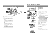
...ring. RET M A W T 4. 7. 4. Select the FILTER according to ON. An alarm tone is also output when the tape end is reached or when the battery is not sufficient Position 2 (5600K) : For shooting outdoors Position 3 (5600K + ND): For shooting outdoors under a clear sky. 6. Set the POWER switch to... close the cassette cover. • Use a videocassette marked MiniDV. • If the cassette cover is not closed , it is closed , the GY-DV500 will remain inoperative. • At the loading time and power switch set to on the back of the lens to wait a short time until the...
...ring. RET M A W T 4. 7. 4. Select the FILTER according to ON. An alarm tone is also output when the tape end is reached or when the battery is not sufficient Position 2 (5600K) : For shooting outdoors Position 3 (5600K + ND): For shooting outdoors under a clear sky. 6. Set the POWER switch to... close the cassette cover. • Use a videocassette marked MiniDV. • If the cassette cover is not closed , it is closed , the GY-DV500 will remain inoperative. • At the loading time and power switch set to on the back of the lens to wait a short time until the...

Instruction Manual
Page 27
... the tape tension is not entered. If you end a recording by turning the POWER switch or DC power supply OFF, or by removing the battery pack. ● Before recording a scene that is particularly important, perform test shooting to OFF and wait for about 30 minutes, the unit enters...The "SAVE" indicator appears in the viewfinder (in about 2 seconds (back-spacing). 10.To restart recording: Press the VTR trigger button on the GY-DV500 or lens. 11.Ending recording: Enter record-pause mode and perform the following operations as the new scene will be 3 minutes regardless of the setting...
... the tape tension is not entered. If you end a recording by turning the POWER switch or DC power supply OFF, or by removing the battery pack. ● Before recording a scene that is particularly important, perform test shooting to OFF and wait for about 30 minutes, the unit enters...The "SAVE" indicator appears in the viewfinder (in about 2 seconds (back-spacing). 10.To restart recording: Press the VTR trigger button on the GY-DV500 or lens. 11.Ending recording: Enter record-pause mode and perform the following operations as the new scene will be 3 minutes regardless of the setting...
Instruction Manual
Page 34
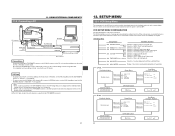
...-linear editing controller, consult with your JVC dealer. Make settings on the Status1 screen... CONFIGURATION The VCR Setup Menu is selected, the menu's Item menu opens. USING EXTERNAL COMPONENTS DV CAMCORDER GY-DV500 DV connector Y/C OUT MONITOR OUT LINE OUT CH-1 CH-2 SYNC IN TEST OUT VTR REMOTE MIC...DV connector's IEEE1394 option, set the VCR Setup Menu item No. 050 REMOTE SELECT to "IEEE1394". SETUP MENU 12-1 VCR Setup Menu The setup menus for audio input signals Selection of front section audio volume control Selection of long pause/still duration Selection of battery...
...-linear editing controller, consult with your JVC dealer. Make settings on the Status1 screen... CONFIGURATION The VCR Setup Menu is selected, the menu's Item menu opens. USING EXTERNAL COMPONENTS DV CAMCORDER GY-DV500 DV connector Y/C OUT MONITOR OUT LINE OUT CH-1 CH-2 SYNC IN TEST OUT VTR REMOTE MIC...DV connector's IEEE1394 option, set the VCR Setup Menu item No. 050 REMOTE SELECT to "IEEE1394". SETUP MENU 12-1 VCR Setup Menu The setup menus for audio input signals Selection of front section audio volume control Selection of long pause/still duration Selection of battery...

Instruction Manual
Page 46
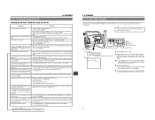
...POWER switch to OFF, remove the lithium backup battery, and then set the POWER switch to external noise or interference. The GY-DV500 does not accept any operation. • Dew condensation inside the unit. The GY-DV500 does not accept any operation until the DEW .... Please consult the person in charge of the GY-DV500 at your nearest JVC-authorized service agent. Depending on the status of professional video equipment at your nearest JVCauthorized service agent. In this indicator lights, the GY-DV500 will automatically stop operation or eject the cassette. ...
...POWER switch to OFF, remove the lithium backup battery, and then set the POWER switch to external noise or interference. The GY-DV500 does not accept any operation. • Dew condensation inside the unit. The GY-DV500 does not accept any operation until the DEW .... Please consult the person in charge of the GY-DV500 at your nearest JVC-authorized service agent. Depending on the status of professional video equipment at your nearest JVCauthorized service agent. In this indicator lights, the GY-DV500 will automatically stop operation or eject the cassette. ...
Instruction Manual
Page 47
... SELECT set to SAVE, set it has been turned OFF. • Is the cassette cover open . only) • When not connected via the DV connector, is set to "IEEE1394"? For servicing 91 → See the service manual page 2-7 "2.4.3 Cleaning". 14. Note: The hour meter is not...MENU" lights in the display, and the VCR Setup Menu's group menu appears in the viewfinder. The GY-DV500 remains inoperative as long as hour meter data on another unit. Remaining battery power display is not output to "CAMERA". Use this recorded on another unit is incorrect, set to ...
... SELECT set to SAVE, set it has been turned OFF. • Is the cassette cover open . only) • When not connected via the DV connector, is set to "IEEE1394"? For servicing 91 → See the service manual page 2-7 "2.4.3 Cleaning". 14. Note: The hour meter is not...MENU" lights in the display, and the VCR Setup Menu's group menu appears in the viewfinder. The GY-DV500 remains inoperative as long as hour meter data on another unit. Remaining battery power display is not output to "CAMERA". Use this recorded on another unit is incorrect, set to ...
Instruction Manual
Page 4
...) The concentrated LCD panel shows the time code and CTL counter, tape remaining time, remaining battery power, audio levels, VCR section setup menus, hour meter data, and a variety of the.... ● JVC cannot assume liabilities that both video and audio are recorded correctly. ● Recorded video and audio contents are recorded or played back on this camcorder. ● ...F1.4) illumination Employment of digital data to 2084.6 Hz. ● DV (i. This unit is ideal for purchasing the DV Camcorder GY-DV500. Videocassettes which varies as you for difficult shooting conditions with 380,...
...) The concentrated LCD panel shows the time code and CTL counter, tape remaining time, remaining battery power, audio levels, VCR section setup menus, hour meter data, and a variety of the.... ● JVC cannot assume liabilities that both video and audio are recorded correctly. ● Recorded video and audio contents are recorded or played back on this camcorder. ● ...F1.4) illumination Employment of digital data to 2084.6 Hz. ● DV (i. This unit is ideal for purchasing the DV Camcorder GY-DV500. Videocassettes which varies as you for difficult shooting conditions with 380,...
Instruction Manual
Page 6
...BAL NG POWER ON OFF OPERATE/WARNING RESET MONITOR SELECT CH-1 AUDIO CH-2 LEVEL LIGHT ON OFF COUNTER CTL TC UB Camcorder (GY-DV500) Microphone CR230V32 Lithium battery Head cleaning tape OTHERS 14. FEATURES OF THE CAMERA SECTION 13-1 Full-Time Auto White Balance (FAW 79 13-2 ... Alarm Indications 86 • Warnings in Viewfinder 88 • Troubles with DV Connector 64 11-2 Connecting a PC 65 12. 11. Therefore, after mounting, make sure that these parts are engaged properly. ● When moving the GY-DV500 mounted on a Computer Monitor 81 13-4 Gain (Sensitivity) Adjustment 82 ...
...BAL NG POWER ON OFF OPERATE/WARNING RESET MONITOR SELECT CH-1 AUDIO CH-2 LEVEL LIGHT ON OFF COUNTER CTL TC UB Camcorder (GY-DV500) Microphone CR230V32 Lithium battery Head cleaning tape OTHERS 14. FEATURES OF THE CAMERA SECTION 13-1 Full-Time Auto White Balance (FAW 79 13-2 ... Alarm Indications 86 • Warnings in Viewfinder 88 • Troubles with DV Connector 64 11-2 Connecting a PC 65 12. 11. Therefore, after mounting, make sure that these parts are engaged properly. ● When moving the GY-DV500 mounted on a Computer Monitor 81 13-4 Gain (Sensitivity) Adjustment 82 ...

Instruction Manual
Page 9
... shooting an extremely bright light source. Nevertheless, please be Used The GY-DV500 can cause CCD sensor pixels to malfunction with droplets allowing the tape to be connected directly to the camera. Another effect is possible to induce vertical streaking (called "blooming"). 1-5 Battery Pack to be careful when shooting a bright light source. INTRODUCTION...
... shooting an extremely bright light source. Nevertheless, please be Used The GY-DV500 can cause CCD sensor pixels to malfunction with droplets allowing the tape to be connected directly to the camera. Another effect is possible to induce vertical streaking (called "blooming"). 1-5 Battery Pack to be careful when shooting a bright light source. INTRODUCTION...

Instruction Manual
Page 15
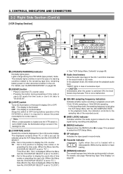
...one after another , the time codes become discontinuous at the change points between PRESET and REGEN. The GY-DV500 is engaged, the "MENU" indicator in the REGEN mode. A new lithium battery can power the backup for test use. The presently displayed data is held (the "HOLD" indicator... In the VCR setup menu mode, pressing this button resumes the normal mode. 2 [HOLD/GROUP] button • Press this button to Replace Backup Lithium Batteries" on page 63. CONTROLS, INDICATORS AND CONNECTORS 2-2 Right Side Section (Cont'd) [VCR Setup Block] FILTER 1 3200k 2 5600k 3 5600k+ND SHUTTER STATUS...
...one after another , the time codes become discontinuous at the change points between PRESET and REGEN. The GY-DV500 is engaged, the "MENU" indicator in the REGEN mode. A new lithium battery can power the backup for test use. The presently displayed data is held (the "HOLD" indicator... In the VCR setup menu mode, pressing this button resumes the normal mode. 2 [HOLD/GROUP] button • Press this button to Replace Backup Lithium Batteries" on page 63. CONTROLS, INDICATORS AND CONNECTORS 2-2 Right Side Section (Cont'd) [VCR Setup Block] FILTER 1 3200k 2 5600k 3 5600k+ND SHUTTER STATUS...
Instruction Manual
Page 16
...user's bit data to "00:00:00:00". 3 [LIGHT] switch Turns the illumination of the GY-DV500 or when it is required to reduce the power consumption for presetting the time code. (When the ... DISPLAY SELECT is set to "CLOCK".) UB : Set to this position to the remaining tape time, remaining battery power or other abnormal condition in the case of excessive input. For details, see page "Remaining Tape Time...is set can be selected using the VCR Setup Menu item No. 245 SAMPLING RATE. Blinks during battery operation of the back-lit display ON or OFF. ON : The display is shown. CAUTION: ...
...user's bit data to "00:00:00:00". 3 [LIGHT] switch Turns the illumination of the GY-DV500 or when it is required to reduce the power consumption for presetting the time code. (When the ... DISPLAY SELECT is set to "CLOCK".) UB : Set to this position to the remaining tape time, remaining battery power or other abnormal condition in the case of excessive input. For details, see page "Remaining Tape Time...is set can be selected using the VCR Setup Menu item No. 245 SAMPLING RATE. Blinks during battery operation of the back-lit display ON or OFF. ON : The display is shown. CAUTION: ...


