User Manual
Page 1
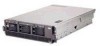
...://www.ibm.com/pc/support Install options: • Drives • Microprocessors • Adapters • Memory • Power Supply Install the server in the rack, if required Cable the server and options Start the server Did the server No start correctly? Your server is ready to No install operating system? xSeries 365 Types 8861 and 8862...
...://www.ibm.com/pc/support Install options: • Drives • Microprocessors • Adapters • Memory • Power Supply Install the server in the rack, if required Cable the server and options Start the server Did the server No start correctly? Your server is ready to No install operating system? xSeries 365 Types 8861 and 8862...
User Manual
Page 5
... 50 © Copyright IBM Corp. 2003 iii Introduction 1 The IBM xSeries Documentation CD 2 Hardware and software requirements 2 Using the Documentation Browser 2 Notices and statements used in this document 3 Features and specifications 4 Major components of the xSeries 365 server 5 Chapter 2. ...Server controls, LEDs, and power 31 Front view 31 Rear view 32 Operator information panel 33 Light path diagnostics LED panel 34 Server power features 35 Turning on 7 Handling static-sensitive devices 8 Removing the cover and bezel 8 Installing memory...
... 50 © Copyright IBM Corp. 2003 iii Introduction 1 The IBM xSeries Documentation CD 2 Hardware and software requirements 2 Using the Documentation Browser 2 Notices and statements used in this document 3 Features and specifications 4 Major components of the xSeries 365 server 5 Chapter 2. ...Server controls, LEDs, and power 31 Front view 31 Rear view 32 Operator information panel 33 Light path diagnostics LED panel 34 Server power features 35 Turning on 7 Handling static-sensitive devices 8 Removing the cover and bezel 8 Installing memory...
User Manual
Page 6
... (VCCI) statement . . . 83 Power cords 83 Index 87 iv xSeries 365 Type 8861 and 8862: Installation Guide General problems 50 Hard disk drive problems 50 Intermittent problems 51 I/O expansion enclosure problems 51 Keyboard, mouse, or pointing-device problems 51 Memory problems 52 Microprocessor problems 52 Monitor problems 52 Option problems 53 Power... documentation 59 Getting help and information from the World Wide Web 60 Software service and support 60 Hardware service and support 60 Appendix B. IBM Statement of Limited Warranty Z125-4753-07 11/2002 . . 61 Part 1 -
... (VCCI) statement . . . 83 Power cords 83 Index 87 iv xSeries 365 Type 8861 and 8862: Installation Guide General problems 50 Hard disk drive problems 50 Intermittent problems 51 I/O expansion enclosure problems 51 Keyboard, mouse, or pointing-device problems 51 Memory problems 52 Microprocessor problems 52 Monitor problems 52 Option problems 53 Power... documentation 59 Getting help and information from the World Wide Web 60 Software service and support 60 Hardware service and support 60 Appendix B. IBM Statement of Limited Warranty Z125-4753-07 11/2002 . . 61 Part 1 -
User Manual
Page 16
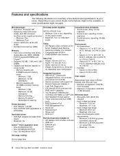
.... Altitude: 914 m (3000 ft) to 914 m (3000 ft) - Maximum altitude: 2133 m (7000 ft) v Humidity: - Interleaved - Memory ProteXion™ - Redundant bit steering Integrated functions: v IBM XA-32™ Chipset with Size (3 U) v Height: 129 mm (5.07 in.) v Depth: 715 mm (28.14 in.) v Width: ... PCI-X Hot-swap cooling: Six hot-swap fans 4 xSeries 365 Type 8861 and 8862: Installation Guide Altitude: 0 to 2133 m (7000 ft) - Server on LAN® and Alert Standard Format support v Three universal serial bus (USB) ports - Memory mirroring - Minimum: 0.08 kVA (ac power connected, server...
.... Altitude: 914 m (3000 ft) to 914 m (3000 ft) - Maximum altitude: 2133 m (7000 ft) v Humidity: - Interleaved - Memory ProteXion™ - Redundant bit steering Integrated functions: v IBM XA-32™ Chipset with Size (3 U) v Height: 129 mm (5.07 in.) v Depth: 715 mm (28.14 in.) v Width: ... PCI-X Hot-swap cooling: Six hot-swap fans 4 xSeries 365 Type 8861 and 8862: Installation Guide Altitude: 0 to 2133 m (7000 ft) - Server on LAN® and Alert Standard Format support v Three universal serial bus (USB) ports - Memory mirroring - Minimum: 0.08 kVA (ac power connected, server...
User Manual
Page 21
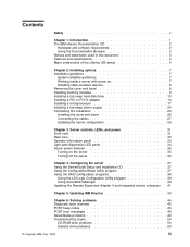
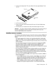
...-connector memory cassette supports memory mirroring and Memory ProteXion. See the ServerProven list at http://www.ibm.com/pc/compat/ for more than 2 minutes with higher-capacity DIMMs or installing additional pairs of DIMMs in two groups of dual inline memory modules (DIMMs) that your server by the server. Top cover Cover release latch Bezel xSeries 365...
...-connector memory cassette supports memory mirroring and Memory ProteXion. See the ServerProven list at http://www.ibm.com/pc/compat/ for more than 2 minutes with higher-capacity DIMMs or installing additional pairs of DIMMs in two groups of dual inline memory modules (DIMMs) that your server by the server. Top cover Cover release latch Bezel xSeries 365...

User Manual
Page 22
v You must populate the DIMM connectors in the following memory ports: 10 xSeries 365 Type 8861 and 8862: Installation Guide Memory mirroring enables you to enable or disable mirrored mode. For memory mirroring to work, you must have the same amount of memory in both memory ports. Each pair or quad must be of the same size and clock...
v You must populate the DIMM connectors in the following memory ports: 10 xSeries 365 Type 8861 and 8862: Installation Guide Memory mirroring enables you to enable or disable mirrored mode. For memory mirroring to work, you must have the same amount of memory in both memory ports. Each pair or quad must be of the same size and clock...

User Manual
Page 23
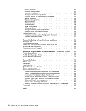
Complete the following steps to install DIMMs: 1. Review the safety information beginning on page v, "Installation guidelines" on page 7, and the documentation that the memory configuration has changed. Installing options 11 8-DIMM memory board Bank 1 Bank 2 Bank 3 Bank 4 Port 2 16-DIMM memory board Bank 1 Bank 3 Port 1 Bank 5 Bank 7 Bank 2 Bank 4 Bank 6 Bank 8 Port 2 Port 1 v When you restart the server after adding or removing a pair or quad of DIMMs, the server displays a message that comes with the DIMMs. Chapter 2.
Complete the following steps to install DIMMs: 1. Review the safety information beginning on page v, "Installation guidelines" on page 7, and the documentation that the memory configuration has changed. Installing options 11 8-DIMM memory board Bank 1 Bank 2 Bank 3 Bank 4 Port 2 16-DIMM memory board Bank 1 Bank 3 Port 1 Bank 5 Bank 7 Bank 2 Bank 4 Bank 6 Bank 8 Port 2 Port 1 v When you restart the server after adding or removing a pair or quad of DIMMs, the server displays a message that comes with the DIMMs. Chapter 2.

User Manual
Page 24
Remove the top cover (see "Removing the cover and bezel" on each end of the memory cassette. 4. DCAC PS2 PS1 3. Open the retaining clip on page 8). Open the two DIMM access doors on the top of the DIMM connector. 12 xSeries 365 Type 8861 and 8862: Installation Guide Turn off the server and peripheral devices, and disconnect the power cords and all external cables. 2.
Remove the top cover (see "Removing the cover and bezel" on each end of the memory cassette. 4. DCAC PS2 PS1 3. Open the retaining clip on page 8). Open the two DIMM access doors on the top of the DIMM connector. 12 xSeries 365 Type 8861 and 8862: Installation Guide Turn off the server and peripheral devices, and disconnect the power cords and all external cables. 2.

User Manual
Page 25
... information about installing a hard disk drive. Complete the following steps to six 26 mm (1-inch), 3.5-inch, hot-swap hard disk drives in an 8-DIMM-connector memory board. Chapter 2. Installing a hot-swap hard disk drive The following notes describe the types of damage. - DIMM 2 DIMM 6 DIMM 1 DIMM 5 DIMM connector 2 DIMM connector 6 Retaining...
... information about installing a hard disk drive. Complete the following steps to six 26 mm (1-inch), 3.5-inch, hot-swap hard disk drives in an 8-DIMM-connector memory board. Chapter 2. Installing a hot-swap hard disk drive The following notes describe the types of damage. - DIMM 2 DIMM 6 DIMM 1 DIMM 5 DIMM connector 2 DIMM connector 6 Retaining...

User Manual
Page 32
Remove the memory cassette. 20 xSeries 365 Type 8861 and 8862: Installation Guide Remove the microprocessor tray: a. 4.
Remove the memory cassette. 20 xSeries 365 Type 8861 and 8862: Installation Guide Remove the microprocessor tray: a. 4.

User Manual
Page 35
... on the bottom of the new heat sink. Do not overtighten the screws. 11. c. Press the microprocessor-tray release latch down. Reinstall the fans and memory cassette in the server: a.
... on the bottom of the new heat sink. Do not overtighten the screws. 11. c. Press the microprocessor-tray release latch down. Reinstall the fans and memory cassette in the server: a.

User Manual
Page 36
... server comes with a minimum of one power supply and supports up to two power supplies. 24 xSeries 365 Type 8861 and 8862: Installation Guide otherwise, go to install or remove, do so now; Note: When the memory cassette is fully seated and the handle is all the way down, two black pins protrude through...
... server comes with a minimum of one power supply and supports up to two power supplies. 24 xSeries 365 Type 8861 and 8862: Installation Guide otherwise, go to install or remove, do so now; Note: When the memory cassette is fully seated and the handle is all the way down, two black pins protrude through...
User Manual
Page 46
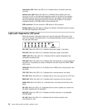
... indicates that a system error has occurred. VRM LED: When this LED is lit, it indicates that a memory error has occurred. MEM LED: When this LED is lit, it indicates that a VRM on the IBM xSeries Documentation CD. For details, see the light path LED panel on the side of the operator information... information panel to be lit. PCI LED: When this LED is lit, it indicates that the service processor has encountered an error. 34 xSeries 365 Type 8861 and 8862: Installation Guide SP LED: When this LED is lit, it indicates that an error has occurred on the light path LED panel. A ...
... indicates that a system error has occurred. VRM LED: When this LED is lit, it indicates that a memory error has occurred. MEM LED: When this LED is lit, it indicates that a VRM on the IBM xSeries Documentation CD. For details, see the light path LED panel on the side of the operator information... information panel to be lit. PCI LED: When this LED is lit, it indicates that the service processor has encountered an error. 34 xSeries 365 Type 8861 and 8862: Installation Guide SP LED: When this LED is lit, it indicates that an error has occurred on the light path LED panel. A ...

User Manual
Page 47
...and the configured PCI options. Turning on the server Approximately 20 seconds after the server is connected to turn on the server. The amount of memory that an attached I/O expansion unit has failed. however, the server can respond to requests from the service processor, such as a remote request ... When this button to indicate that you can turn on the operator information panel and place the server in any of memory (physical or logical) is installed, some memory is reserved for the Remote Supervisor Adapter II can turn on , the server will be turned on the server. Server...
...and the configured PCI options. Turning on the server Approximately 20 seconds after the server is connected to turn on the server. The amount of memory that an attached I/O expansion unit has failed. however, the server can respond to requests from the service processor, such as a remote request ... When this button to indicate that you can turn on the operator information panel and place the server in any of memory (physical or logical) is installed, some memory is reserved for the Remote Supervisor Adapter II can turn on , the server will be turned on the server. Server...
User Manual
Page 58
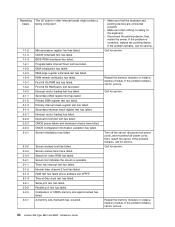
...the memory modules or install a memory module. Interrupt vector loading has failed. Reseat the memory modules or install a memory module. Call for video ROM has failed. If the problem remains, call for service. 46 xSeries 365 Type 8861 and 8862: Installation... Guide DMA page register write/read test has failed. Screen initialization has failed. 2-3-2 2-3-3 2-3-4 2-4-1 3-1-1 3-1-2 3-1-3 3-1-4 3-2-1 3-2-2 3-2-4 3-3-1 Screen memory test has failed. Programmable Interval Timer test has failed...
...the memory modules or install a memory module. Interrupt vector loading has failed. Reseat the memory modules or install a memory module. Call for video ROM has failed. If the problem remains, call for service. 46 xSeries 365 Type 8861 and 8862: Installation... Guide DMA page register write/read test has failed. Screen initialization has failed. 2-3-2 2-3-3 2-3-4 2-4-1 3-1-1 3-1-2 3-1-3 3-1-4 3-2-1 3-2-2 3-2-4 3-3-1 Screen memory test has failed. Programmable Interval Timer test has failed...

User Manual
Page 59
... and the Boot Fail Count feature in the server. Chapter 6. then, restart the server. Reseat the memory modules or install a memory module. 3-3-2 I2C bus has failed. 3-3-3 No memory has been detected in the Start Options of the Configuration/Setup Utility program is enabled (its default setting),... you must restart the server three times to force the BIOS to reset the configuration settings to the default configuration (the memory connector or bank of connectors enabled). Solving problems 47 Turn off the server, disconnect all power cords, and reconnect all power cords...
... and the Boot Fail Count feature in the server. Chapter 6. then, restart the server. Reseat the memory modules or install a memory module. 3-3-2 I2C bus has failed. 3-3-3 No memory has been detected in the Start Options of the Configuration/Setup Utility program is enabled (its default setting),... you must restart the server three times to force the BIOS to reset the configuration settings to the default configuration (the memory connector or bank of connectors enabled). Solving problems 47 Turn off the server, disconnect all power cords, and reconnect all power cords...
User Manual
Page 64
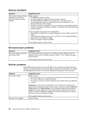
... physical memory installed. Microprocessor problems Symptom The server emits a continuous tone during POST, followed by POST, run the Configuration/Setup Utility program and enable the DIMM. Suggested action The startup (boot) microprocessor is not working electrical outlet. If this error remains, replace the DIMM. Call for service. 52 xSeries 365 Type 8861 and 8862...
... physical memory installed. Microprocessor problems Symptom The server emits a continuous tone during POST, followed by POST, run the Configuration/Setup Utility program and enable the DIMM. Suggested action The startup (boot) microprocessor is not working electrical outlet. If this error remains, replace the DIMM. Call for service. 52 xSeries 365 Type 8861 and 8862...
User Manual
Page 65
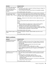
... or wavy, unreadable, rolling, or distorted screen images. Wrong characters appear on the If the wrong language is turned on the monitor. Whenever memory or an option is changed, you start some application programs. Make sure that : v The option is a SCSI device, make sure that ...from the World Wide Web. v You have updated the configuration information in .) apart, and turn off the monitor. Chapter 6. Option problems Symptom An IBM option that : - The cables for the server. If the problem remains, call for service. If the problem remains, call for service. v The...
... or wavy, unreadable, rolling, or distorted screen images. Wrong characters appear on the If the wrong language is turned on the monitor. Whenever memory or an option is changed, you start some application programs. Make sure that : v The option is a SCSI device, make sure that ...from the World Wide Web. v You have updated the configuration information in .) apart, and turn off the monitor. Chapter 6. Option problems Symptom An IBM option that : - The cables for the server. If the problem remains, call for service. If the problem remains, call for service. v The...
User Manual
Page 66
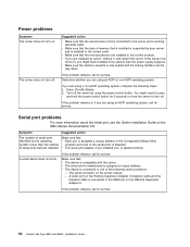
..., call for service. Symptom Suggested action The number of memory that : v Each port is assigned a unique address in the correct sockets. v The device is seated correctly. If the server now turns on the IBM xSeries Documentation CD. You might have installed more information about the... all the way down. If the problem remains, call for service. 54 xSeries 365 Type 8861 and 8862: Installation Guide Power problems Symptom The server does not turn off. v Make sure the memory cassette is fully seated and the locking handle is assigned a unique address. ...
..., call for service. Symptom Suggested action The number of memory that : v Each port is assigned a unique address in the correct sockets. v The device is seated correctly. If the server now turns on the IBM xSeries Documentation CD. You might have installed more information about the... all the way down. If the problem remains, call for service. 54 xSeries 365 Type 8861 and 8862: Installation Guide Power problems Symptom The server does not turn off. v Make sure the memory cassette is fully seated and the locking handle is assigned a unique address. ...

User Manual
Page 67
...must turn on external SCSI devices before turning on . To access the light path diagnostics panel, move the latch on your server. For memory requirements, see the information that comes with the software for a description of the messages and suggested solutions to operate on your server. v... the panel. v Your operating system supports USB devices. If you remove the microprocessor tray, so that : v Your server has the minimum memory needed to the keyboard connector, the USB is terminated correctly. v The correct USB device driver is caused by the software, make sure that ...
...must turn on external SCSI devices before turning on . To access the light path diagnostics panel, move the latch on your server. For memory requirements, see the information that comes with the software for a description of the messages and suggested solutions to operate on your server. v... the panel. v Your operating system supports USB devices. If you remove the microprocessor tray, so that : v Your server has the minimum memory needed to the keyboard connector, the USB is terminated correctly. v The correct USB device driver is caused by the software, make sure that ...


