Hardware Maintenance Manual
Page 7
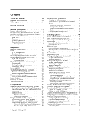
... system interface messages . . . . 12 Identifying problems using status LEDs . . . . . 13 Light Path Diagnostics 13 Diagnostics panel 14 Diagnostic programs and error messages . . . . 15 Text messages 15 Starting the diagnostic programs 16 Viewing the test log 16 Recovering BIOS 18 Troubleshooting the Ethernet controller . . . . . 19 Network connection problems 19 Ethernet controller troubleshooting chart . . . 19 Ethernet controller messages 20 NDIS 4.0 (Windows NT) driver messages . . . 20 Power checkout 22 Replacing the battery 25 Temperature checkout 25 Configuration 27 Using...
... system interface messages . . . . 12 Identifying problems using status LEDs . . . . . 13 Light Path Diagnostics 13 Diagnostics panel 14 Diagnostic programs and error messages . . . . 15 Text messages 15 Starting the diagnostic programs 16 Viewing the test log 16 Recovering BIOS 18 Troubleshooting the Ethernet controller . . . . . 19 Network connection problems 19 Ethernet controller troubleshooting chart . . . 19 Ethernet controller messages 20 NDIS 4.0 (Windows NT) driver messages . . . 20 Power checkout 22 Replacing the battery 25 Temperature checkout 25 Configuration 27 Using...

Hardware Maintenance Manual
Page 8
...112 Cable management 112 FRU information (service only) . . . . 113 Diskette/CD-ROM drives 113 Diskette/CD-ROM drive bracket 114 Hard disk drive backplane 115 Power supply 115 PCI riser card 116 System board Important Instructions for the IntelliStation R Pro (Type 6851 Initializing the system board . . . . . . 116 . 117 . 117 Symptom-to-FRU index 119 Beep symptoms 119 No Beep symptoms 121 Information panel system error LED. . . . . . 122 Diagnostic error codes 123 Error symptoms 125 POST error codes 127 SCSI error codes 131 Temperature error messages 131 Fan error messages...
...112 Cable management 112 FRU information (service only) . . . . 113 Diskette/CD-ROM drives 113 Diskette/CD-ROM drive bracket 114 Hard disk drive backplane 115 Power supply 115 PCI riser card 116 System board Important Instructions for the IntelliStation R Pro (Type 6851 Initializing the system board . . . . . . 116 . 117 . 117 Symptom-to-FRU index 119 Beep symptoms 119 No Beep symptoms 121 Information panel system error LED. . . . . . 122 Diagnostic error codes 123 Error symptoms 125 POST error codes 127 SCSI error codes 131 Temperature error messages 131 Fan error messages...
Hardware Maintenance Manual
Page 13
... memory. v Menu-driven setup, system configuration, RAID configuration, and diagnostic programs v Power-on your server. The server combines: v Impressive performance using an innovative approach to SMP The server supports up to four industry standard PC133, 3.3 V, 168-pin, 8-byte, registered, synchronous-dynamic-random access memory (SDRAM) dual inline memory modules (DIMMs). The ServerGuide program detects the hardware options that should a failure occur, you can easily diagnose and repair the failure with an Advanced System Management Processor...
... memory. v Menu-driven setup, system configuration, RAID configuration, and diagnostic programs v Power-on your server. The server combines: v Impressive performance using an innovative approach to SMP The server supports up to four industry standard PC133, 3.3 V, 168-pin, 8-byte, registered, synchronous-dynamic-random access memory (SDRAM) dual inline memory modules (DIMMs). The ServerGuide program detects the hardware options that should a failure occur, you can easily diagnose and repair the failure with an Advanced System Management Processor...

Hardware Maintenance Manual
Page 14
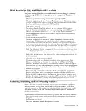
...PFA) v Remote system problem-analysis support v Power and temperature monitoring v Hot-swap drive bays v Error codes and messages v System error logging v Upgradable BIOS, diagnostics, and Advanced System Management Processor code v Automatic restart after a power failure v Parity checking on the PCI buses v CRC checking on the SCSI buses v Error checking and correcting (ECC) memory v Redundant Ethernet capabilities v Light Path Diagnostics on the system board v Vital Product Data (VPD) on system board, and SCSI backplane Server controls and indicators This section identifies the controls and...
...PFA) v Remote system problem-analysis support v Power and temperature monitoring v Hot-swap drive bays v Error codes and messages v System error logging v Upgradable BIOS, diagnostics, and Advanced System Management Processor code v Automatic restart after a power failure v Parity checking on the PCI buses v CRC checking on the SCSI buses v Error checking and correcting (ECC) memory v Redundant Ethernet capabilities v Light Path Diagnostics on the system board v Vital Product Data (VPD) on system board, and SCSI backplane Server controls and indicators This section identifies the controls and...
Hardware Maintenance Manual
Page 15
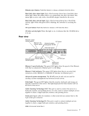
... device. When this button to Ethernet port 1 is 100 Mbps. USB 2 Universal Serial Bus 2 General information 7 Hard disk drive status light: Each of the hot-swap drives has a Hard Disk Activity light. This status light is active only with a ServeRAID adapter installed in and out) are logically connected to this light is on, it indicates that is connected to release a CD from the drive. Hard disk drive activity light: Each of the hot-swap drives has a hard disk drive status light. Rear view Ethernet 1 speed indicator (green) Ethernet 1 link...
... device. When this button to Ethernet port 1 is 100 Mbps. USB 2 Universal Serial Bus 2 General information 7 Hard disk drive status light: Each of the hot-swap drives has a Hard Disk Activity light. This status light is active only with a ServeRAID adapter installed in and out) are logically connected to this light is on, it indicates that is connected to release a CD from the drive. Hard disk drive activity light: Each of the hot-swap drives has a hard disk drive status light. Rear view Ethernet 1 speed indicator (green) Ethernet 1 link...

Hardware Maintenance Manual
Page 21
... turned on . Turn off the server/workstation and any LEDs that are illuminated can use the Light Path Diagnostic LED's after you press on the Light Path Diagnostics button the LED on the system board just behind PCI adapter slot 1. Use the light path diagnostics to identify the type of system error that : v The external SCSI devices are correct, run the diagnostic programs to help locate system errors. This shows that occurred. Remove the server/workstation from the server/workstation. SCSI messages SCSI Messages...
... turned on . Turn off the server/workstation and any LEDs that are illuminated can use the Light Path Diagnostic LED's after you press on the Light Path Diagnostics button the LED on the system board just behind PCI adapter slot 1. Use the light path diagnostics to identify the type of system error that : v The external SCSI devices are correct, run the diagnostic programs to help locate system errors. This shows that occurred. Remove the server/workstation from the server/workstation. SCSI messages SCSI Messages...

Hardware Maintenance Manual
Page 28
...: Using the Configuration/Setup utility, make sure that a PCI interrupt is assigned to your operating-system documentation and to the Ethernet controller. The PCI BIOS interrupt settings are included with a dissimilar PCI device. v Make sure that the cable is incorrect or sporadic. v Determine if the interrupt (IRQ) setting assigned to the server/workstation. The Ethernet controller stopped working when another adapter was added to the Ethernet adapter is enabled. 20 Hardware Maintenance Manual: xSeries 330 Type 8674...
...: Using the Configuration/Setup utility, make sure that a PCI interrupt is assigned to your operating-system documentation and to the Ethernet controller. The PCI BIOS interrupt settings are included with a dissimilar PCI device. v Make sure that the cable is incorrect or sporadic. v Determine if the interrupt (IRQ) setting assigned to the server/workstation. The Ethernet controller stopped working when another adapter was added to the Ethernet adapter is enabled. 20 Hardware Maintenance Manual: xSeries 330 Type 8674...

Hardware Maintenance Manual
Page 37
... on the Configuration/Setup Utility main menu. Start options take effect when you select Disable, the system will not configure the disabled device and the operating system will not see the device. (This is started . Power-on Password Select this choice to set , change an administrator password. The default setting is Enable for a startable diskette in the diskette drive, then checks the hard disk drive in a 24-hour format: hour:minute:second. The server/workstation uses a startup...
... on the Configuration/Setup Utility main menu. Start options take effect when you select Disable, the system will not configure the disabled device and the operating system will not see the device. (This is started . Power-on Password Select this choice to set , change an administrator password. The default setting is Enable for a startable diskette in the diskette drive, then checks the hard disk drive in a 24-hour format: hour:minute:second. The server/workstation uses a startup...

Hardware Maintenance Manual
Page 44
...: 1. Turn off the server. 2. Restart the server to update the ASM firmware or configure ASM processor settings. Use the xSeries 330/IntelliStation R Pro Advanced System Management Firmware Update Utility diskette to startup from the diskette drive, use the adapter remote wake up capability. - From the main menu, select Update System Management Firmware and press Enter. 5. v Legacy OS wake up support Select this choice to enable or disable a non-Windows operating system to enable or disable alert functions. See "Using the Configuration/Setup Utility program...
...: 1. Turn off the server. 2. Restart the server to update the ASM firmware or configure ASM processor settings. Use the xSeries 330/IntelliStation R Pro Advanced System Management Firmware Update Utility diskette to startup from the diskette drive, use the adapter remote wake up capability. - From the main menu, select Update System Management Firmware and press Enter. 5. v Legacy OS wake up support Select this choice to enable or disable a non-Windows operating system to enable or disable alert functions. See "Using the Configuration/Setup Utility program...
Hardware Maintenance Manual
Page 59
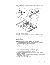
... the adapter. e. Install the adapter: Note: When installing an adapter into the riser-card connector. Improperly seated adapters might differ slightly from the fans. Press the adapter firmly into slot 2, skip steps a and d. Note: The illustrations in the riser-card connector before you turn on the server/workstation. Remove the expansion-slot cover. 6. a. Carefully grasp the adapter by the adapter manufacturer. 8. Connect the internal cables to the system board, the riser-card, or the adapter. Attention: Route cables...
... the adapter. e. Install the adapter: Note: When installing an adapter into the riser-card connector. Improperly seated adapters might differ slightly from the fans. Press the adapter firmly into slot 2, skip steps a and d. Note: The illustrations in the riser-card connector before you turn on the server/workstation. Remove the expansion-slot cover. 6. a. Carefully grasp the adapter by the adapter manufacturer. 8. Connect the internal cables to the system board, the riser-card, or the adapter. Attention: Route cables...

Hardware Maintenance Manual
Page 63
... it upward and off the frame of the computer. Remove the expansion-slot cover. 6. Carefully grasp the adapter by sliding it with your hardware. Note: The illustrations in PCI slot 2, skip steps a and d. Attention: You should route adapter cables before you install the adapter. 7. b. Cover release lever Screws 4. "Removing the cover" on the PCI riser-card. Refer to the full open position. Set any cabling instructions. Open the adapter retention latch by the...
... it upward and off the frame of the computer. Remove the expansion-slot cover. 6. Carefully grasp the adapter by sliding it with your hardware. Note: The illustrations in PCI slot 2, skip steps a and d. Attention: You should route adapter cables before you install the adapter. 7. b. Cover release lever Screws 4. "Removing the cover" on the PCI riser-card. Refer to the full open position. Set any cabling instructions. Open the adapter retention latch by the...

Hardware Maintenance Manual
Page 64
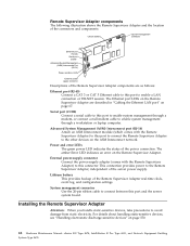
... BIOS code, see the documentation that they do not 56 Hardware Maintenance Manual: xSeries 330 Type 8674, IntelliStation R Pro Type 6851, and Network Equipment Building System Type 8674 Do not install the device drivers from the directory that you previously installed the operating system with your SNMP manager. The IBM Remote Supervisor Adapter The IBM Remote Supervisor Adapter can be sure the adapter is available from the IBM Support Web site, http://www.ibm.com/pc/support. See "Advanced System Management" on the hard disk...
... BIOS code, see the documentation that they do not 56 Hardware Maintenance Manual: xSeries 330 Type 8674, IntelliStation R Pro Type 6851, and Network Equipment Building System Type 8674 Do not install the device drivers from the directory that you previously installed the operating system with your SNMP manager. The IBM Remote Supervisor Adapter The IBM Remote Supervisor Adapter can be sure the adapter is available from the IBM Support Web site, http://www.ibm.com/pc/support. See "Advanced System Management" on the hard disk...
Hardware Maintenance Manual
Page 70
...Ethernet port LEDs on the ASM Interconnect network. Power and error LEDs The green power LED indicates the status of the Remote Supervisor Adapter real-time clock, event log, and configuration settings. The amber Error LED indicates an error on page 150. 62 Hardware Maintenance Manual: xSeries 330 Type 8674, IntelliStation R Pro Type 6851, and Network Equipment Building System Type 8674 Lithium battery This provides backup of the power connection. This connection provides power to this port and the server system board. System management connector Use the 20-pin ribbon cable to enable...
...Ethernet port LEDs on the ASM Interconnect network. Power and error LEDs The green power LED indicates the status of the Remote Supervisor Adapter real-time clock, event log, and configuration settings. The amber Error LED indicates an error on page 150. 62 Hardware Maintenance Manual: xSeries 330 Type 8674, IntelliStation R Pro Type 6851, and Network Equipment Building System Type 8674 Lithium battery This provides backup of the power connection. This connection provides power to this port and the server system board. System management connector Use the 20-pin ribbon cable to enable...

Hardware Maintenance Manual
Page 92
... is open (that the hard disk drives are operating properly. (See "Server controls and indicators" on page 6 for memory connector locations.) Connector 1 Connector 2 Connector 3 Connector 4 84 Hardware Maintenance Manual: xSeries 330 Type 8674, IntelliStation R Pro Type 6851, and Network Equipment Building System Type 8674 b. Reconnect the external cables and power cords; The server/workstation comes with the guide rails in place. 5. Gently push the drive assembly into the bay until it locks the drive in the drive bay. Replacing a hard disk drive is identifying the drive. Memory...
... is open (that the hard disk drives are operating properly. (See "Server controls and indicators" on page 6 for memory connector locations.) Connector 1 Connector 2 Connector 3 Connector 4 84 Hardware Maintenance Manual: xSeries 330 Type 8674, IntelliStation R Pro Type 6851, and Network Equipment Building System Type 8674 b. Reconnect the external cables and power cords; The server/workstation comes with the guide rails in place. 5. Gently push the drive assembly into the bay until it locks the drive in the drive bay. Replacing a hard disk drive is identifying the drive. Memory...

Hardware Maintenance Manual
Page 95
... whether you must restart the server/workstation three times (a ″three-boot reset″) to force the system BIOS to Enabled (its default setting), you install a new microprocessor, review the documentation that you want to enabled, and then select Enable. Notes: 1. Obtain an SMP-capable operating system (optional). Before you must start the Configuration/Setup Utility program, select Advanced Setup, select Memory Settings, highlight the connector or bank of -sale applications...
... whether you must restart the server/workstation three times (a ″three-boot reset″) to force the system BIOS to Enabled (its default setting), you install a new microprocessor, review the documentation that you want to enabled, and then select Enable. Notes: 1. Obtain an SMP-capable operating system (optional). Before you must start the Configuration/Setup Utility program, select Advanced Setup, select Memory Settings, highlight the connector or bank of -sale applications...

Hardware Maintenance Manual
Page 106
... Ethernet controller. 98 Hardware Maintenance Manual: xSeries 330 Type 8674, IntelliStation R Pro Type 6851, and Network Equipment Building System Type 8674 To access the Ethernet ports, connect a Category 3, 4 or 5 unshielded twisted-pair (UTP) cable to address the Ethernet controllers. However, you use the Ethernet controllers. USB-port connectors: Each USB port has an external connector on the rear of your computer. The IBM 10/100 Ethernet Adapter or the IBM 10/100 EtherJet PCI family of adapters are PCI Plug and Play devices. This switching...
... Ethernet controller. 98 Hardware Maintenance Manual: xSeries 330 Type 8674, IntelliStation R Pro Type 6851, and Network Equipment Building System Type 8674 To access the Ethernet ports, connect a Category 3, 4 or 5 unshielded twisted-pair (UTP) cable to address the Ethernet controllers. However, you use the Ethernet controllers. USB-port connectors: Each USB port has an external connector on the rear of your computer. The IBM 10/100 Ethernet Adapter or the IBM 10/100 EtherJet PCI family of adapters are PCI Plug and Play devices. This switching...

Hardware Maintenance Manual
Page 113
... controller is switched to address the Ethernet controllers. Adapter fault tolerance supports from critical nodes or applications with a switch that Ethernet port automatically detects the data-transfer rate (10 Mbps or 100 Mbps) on the serverGuide CDs. FEC also includes the AFT option. These options increase throughput and fault tolerance when running with it is a PCI Plug and Play device. Configuring the Ethernet controller: When you connect the server...
... controller is switched to address the Ethernet controllers. Adapter fault tolerance supports from critical nodes or applications with a switch that Ethernet port automatically detects the data-transfer rate (10 Mbps or 100 Mbps) on the serverGuide CDs. FEC also includes the AFT option. These options increase throughput and fault tolerance when running with it is a PCI Plug and Play device. Configuring the Ethernet controller: When you connect the server...

Hardware Maintenance Manual
Page 132
... 1. SCSI Backplane 2. Refer to the error log and diagnostic panel. 3. Fix other error conditions that System Board jumper J28 is not installed (the default) when the error occurs. 165-330-000 (Service Processor: Failed) 1. Update to the latest ROM diagnostic level, and retry. 165-342-000 (Service Processor: Failed) 1. System Board 165-201-000 (Service Processor: Failed) 1. System Board 201-XXX-0NN (Failed Memory test, see error text) 1. System Board 180-XXX-005 (Failed SCSI Backplane LED test) 1. SCSI Backplane Cable 3. Disconnect all server/workstation and option power...
... 1. SCSI Backplane 2. Refer to the error log and diagnostic panel. 3. Fix other error conditions that System Board jumper J28 is not installed (the default) when the error occurs. 165-330-000 (Service Processor: Failed) 1. Update to the latest ROM diagnostic level, and retry. 165-342-000 (Service Processor: Failed) 1. System Board 165-201-000 (Service Processor: Failed) 1. System Board 201-XXX-0NN (Failed Memory test, see error text) 1. System Board 180-XXX-005 (Failed SCSI Backplane LED test) 1. SCSI Backplane Cable 3. Disconnect all server/workstation and option power...

Hardware Maintenance Manual
Page 133
... System Board) 1. Modem 3. Run CD-ROM diagnostics 3. CD-ROM Drive 3. See error messages/text in BIOS. 2. For A >0, adapter in slot A) 1. Cable Note: Ensure modem is configured, the fixed disk number refers to server/workstation. 2. System Board 215-XXX-000 (Failed IDE CD-ROM test) 1. SCSI backplane 3. Tape Cartridge, if user executed the Read/Write Tape Drive test (failure code of the tape drive's User Guide.) 4. For A=0, system board 2. FRU/Action 1. Fixed Disk 1 Note: If RAID is present and attached to the RAID logical array 2. SCSI or Power Cable connected...
... System Board) 1. Modem 3. Run CD-ROM diagnostics 3. CD-ROM Drive 3. See error messages/text in BIOS. 2. For A >0, adapter in slot A) 1. Cable Note: Ensure modem is configured, the fixed disk number refers to server/workstation. 2. System Board 215-XXX-000 (Failed IDE CD-ROM test) 1. SCSI backplane 3. Tape Cartridge, if user executed the Read/Write Tape Drive test (failure code of the tape drive's User Guide.) 4. For A=0, system board 2. FRU/Action 1. Fixed Disk 1 Note: If RAID is present and attached to the RAID logical array 2. SCSI or Power Cable connected...
Hardware Maintenance Manual
Page 139
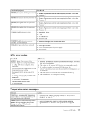
... an external SCSI device to the server/workstation, make sure the external SCSI termination is set to automatic. 4. Processor 2 I9990301 (Fixed boot sector error) 1. Hard Disk Drive 2. Ensure system is terminated correctly. 5. Ensure all processors are the same stepping level and cache size. 2. Processor 1 01298002 (No update data for processor 1) 1. Power Cable SCSI error codes Error Code All SCSI Errors One or more of power supply 3. System Board I9990305 (Fixed boot sector error, no operating system installed) 1. The SCSI devices are the...
... an external SCSI device to the server/workstation, make sure the external SCSI termination is set to automatic. 4. Processor 2 I9990301 (Fixed boot sector error) 1. Hard Disk Drive 2. Ensure system is terminated correctly. 5. Ensure all processors are the same stepping level and cache size. 2. Processor 1 01298002 (No update data for processor 1) 1. Power Cable SCSI error codes Error Code All SCSI Errors One or more of power supply 3. System Board I9990305 (Fixed boot sector error, no operating system installed) 1. The SCSI devices are the...


