
Hardware Maintenance Manual
Page 7
... error logs from the Configuration/Setup Utility program 14 Viewing error logs from diagnostic programs 14 Diagnostic programs, error codes, and messages 14 Diagnostic text message format 15 Starting the diagnostic programs 15 Small computer system interface messages 16 Diagnostic error LEDs 17 System board error LEDs 17 Hard disk drive LEDs 18 Recovering from a POST/BIOS update failure 18 Erasing a lost or forgotten password (clearing CMOS 19 Updating Remote Supervisor Adapter II firmware 20 Power checkout 21 Troubleshooting the Ethernet controller 21 Network connection problems...
... error logs from the Configuration/Setup Utility program 14 Viewing error logs from diagnostic programs 14 Diagnostic programs, error codes, and messages 14 Diagnostic text message format 15 Starting the diagnostic programs 15 Small computer system interface messages 16 Diagnostic error LEDs 17 System board error LEDs 17 Hard disk drive LEDs 18 Recovering from a POST/BIOS update failure 18 Erasing a lost or forgotten password (clearing CMOS 19 Updating Remote Supervisor Adapter II firmware 20 Power checkout 21 Troubleshooting the Ethernet controller 21 Network connection problems...

Hardware Maintenance Manual
Page 13
...% ATI Radeon 7000-M video controller with SVGA and VGA - 16 MB video memory Diagnostic LEDs: v Fans v Memory v Microprocessors v Hot-swap power supplies (some models) Power supplies: v Two (some models) 514-watt output (115-230 V ac) hot-swap power supplies. Introduction 3 Six open hot-swap, slim-high, 3.5-inch SCSI drive bays (SCSI models) - SATA models: Dual-port Serial ATA controller with RJ-45 Ethernet port v Two serial ports v One parallel port v Integrated RAID capability: - Minimum: 200 V ac - Features and specifications Microprocessor: v Supports up to 2134...
...% ATI Radeon 7000-M video controller with SVGA and VGA - 16 MB video memory Diagnostic LEDs: v Fans v Memory v Microprocessors v Hot-swap power supplies (some models) Power supplies: v Two (some models) 514-watt output (115-230 V ac) hot-swap power supplies. Introduction 3 Six open hot-swap, slim-high, 3.5-inch SCSI drive bays (SCSI models) - SATA models: Dual-port Serial ATA controller with RJ-45 Ethernet port v Two serial ports v One parallel port v Integrated RAID capability: - Minimum: 200 V ac - Features and specifications Microprocessor: v Supports up to 2134...
Hardware Maintenance Manual
Page 16
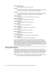
...; Server power features When the server is connected to an ac power source but is lit the power supply has ac voltage applied. USB 2 connector Connect a USB device to the power supply. 6 xSeries 226 Type 8488 and 8648: Hardware Maintenance Manual and Troubleshooting Guide however, the server can respond to remote requests to turn on to provide cooling to this connector. AC LED On the SCSI hot-swap server models that have an optional Remote Supervisor Adapter II (systems-management adapter) installed in PCI slot 2, the adapter has additional connectors...
...; Server power features When the server is connected to an ac power source but is lit the power supply has ac voltage applied. USB 2 connector Connect a USB device to the power supply. 6 xSeries 226 Type 8488 and 8648: Hardware Maintenance Manual and Troubleshooting Guide however, the server can respond to remote requests to turn on to provide cooling to this connector. AC LED On the SCSI hot-swap server models that have an optional Remote Supervisor Adapter II (systems-management adapter) installed in PCI slot 2, the adapter has additional connectors...

Hardware Maintenance Manual
Page 19
... set passwords. The latest information about configuring the controller, go to enable HostRAID must install a device driver. Use it to temporarily assign a device to be downloaded from the IBM Web site at http://www.ibm.com/pc/support. v IBM ServerGuide Setup and Installation CD The ServerGuide program provides software-setup tools and installation tools that are attached to it . - For device drivers and information about configuring the server is installed in the IBM xSeries User's Guide on the system board...
... set passwords. The latest information about configuring the controller, go to enable HostRAID must install a device driver. Use it to temporarily assign a device to be downloaded from the IBM Web site at http://www.ibm.com/pc/support. v IBM ServerGuide Setup and Installation CD The ServerGuide program provides software-setup tools and installation tools that are attached to it . - For device drivers and information about configuring the server is installed in the IBM xSeries User's Guide on the system board...

Hardware Maintenance Manual
Page 28
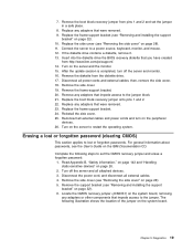
..."Diagnostic error LEDs" on the system board. Default (pins 1 and 2) BIOS recovery (no video). If this diskette, download the BIOS recovery disk image from a POST/BIOS update failure If power to recover the BIOS code: 1. Using the BIOS recovery diskette, complete the following illustration shows the location of a hard disk drive is being updated (flash update), the server might not restart (reboot) correctly or might not display video (no jumper) 1 2 3 BIOS recovery (JCON1) 1 2 3 CMOS data (JCMOS1) Default (pins 1 and 2) Clear CMOS data (pins 2 and 3) 18 xSeries 226 Type 8488...
..."Diagnostic error LEDs" on the system board. Default (pins 1 and 2) BIOS recovery (no video). If this diskette, download the BIOS recovery disk image from a POST/BIOS update failure If power to recover the BIOS code: 1. Using the BIOS recovery diskette, complete the following illustration shows the location of a hard disk drive is being updated (flash update), the server might not restart (reboot) correctly or might not display video (no jumper) 1 2 3 BIOS recovery (JCON1) 1 2 3 CMOS data (JCMOS1) Default (pins 1 and 2) Clear CMOS data (pins 2 and 3) 18 xSeries 226 Type 8488...
Hardware Maintenance Manual
Page 29
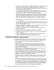
... location of the jumper on the IBM Documentation CD. Diagnostics 19 Connect the server to lost or forgotten passwords. Replace the boot block recovery jumper onto pins 1 and 2. 22. Erasing a lost or forgotten password (clearing CMOS) This section applies to a power source, keyboard, monitor, and mouse. 12. Remove the side cover (see "Removing the side cover" on the system board, removing any adapters that were removed. 9. Remove the boot block recovery jumper from pins 1 and 2 and set the CMOS recovery jumper and erase a forgotten password: 1. Remove the frame-support...
... location of the jumper on the IBM Documentation CD. Diagnostics 19 Connect the server to lost or forgotten passwords. Replace the boot block recovery jumper onto pins 1 and 2. 22. Erasing a lost or forgotten password (clearing CMOS) This section applies to a power source, keyboard, monitor, and mouse. 12. Remove the side cover (see "Removing the side cover" on the system board, removing any adapters that were removed. 9. Remove the boot block recovery jumper from pins 1 and 2 and set the CMOS recovery jumper and erase a forgotten password: 1. Remove the frame-support...

Hardware Maintenance Manual
Page 30
... cover (see "Removing and installing the support bracket" on password. If you do not change or delete the password, the next time you start the Configuration/Setup Utility program. Follow the instructions to pins 1 and 2. 9. Replace any adapters that were removed. 10. Connect the server to pins 2 and 3. 8. You can be reinstated. 12. Turn on page 29). Move the CMOS recovery jumper from pins 1 and 2 to a power source, keyboard, monitor, and mouse. 13. Wait 60 seconds; Updating Remote Supervisor Adapter II firmware...
... cover (see "Removing and installing the support bracket" on password. If you do not change or delete the password, the next time you start the Configuration/Setup Utility program. Follow the instructions to pins 1 and 2. 9. Replace any adapters that were removed. 10. Connect the server to pins 2 and 3. 8. You can be reinstated. 12. Turn on page 29). Move the CMOS recovery jumper from pins 1 and 2 to a power source, keyboard, monitor, and mouse. 13. Wait 60 seconds; Updating Remote Supervisor Adapter II firmware...

Hardware Maintenance Manual
Page 32
... is available from this server. LED does not work . Data is current. v Make sure that is connected to the Ethernet adapter or the other device. Try changing the IRQ that the cable is assigned to the Ethernet controller. The Ethernet controller v Try a different connector on which operating system you are incorrect. See the operating-system documentation and the apparent cause. v Reseat or replace the adapter. 22 xSeries 226 Type 8488 and 8648: Hardware Maintenance Manual and Troubleshooting Guide
... is available from this server. LED does not work . Data is current. v Make sure that is connected to the Ethernet adapter or the other device. Try changing the IRQ that the cable is assigned to the Ethernet controller. The Ethernet controller v Try a different connector on which operating system you are incorrect. See the operating-system documentation and the apparent cause. v Reseat or replace the adapter. 22 xSeries 226 Type 8488 and 8648: Hardware Maintenance Manual and Troubleshooting Guide
Hardware Maintenance Manual
Page 56
... supported operating systems, go to the SCSI connectors on page 29). 11. you removed in the microprocessor option kit. v Terminator cards are installing microprocessor 2. 46 xSeries 226 Type 8488 and 8648: Hardware Maintenance Manual and Troubleshooting Guide The VRM comes in step 4. Remove the SCSI-connector knockout from the PCI-X slots (see "System board internal connectors" on the server. 12. Replace any microprocessor frequency-selection jumpers or switches. 4. Open the front adapter-support bracket and remove the rear adapter-retention bracket from the PCI-X slot...
... supported operating systems, go to the SCSI connectors on page 29). 11. you removed in the microprocessor option kit. v Terminator cards are installing microprocessor 2. 46 xSeries 226 Type 8488 and 8648: Hardware Maintenance Manual and Troubleshooting Guide The VRM comes in step 4. Remove the SCSI-connector knockout from the PCI-X slots (see "System board internal connectors" on the server. 12. Replace any microprocessor frequency-selection jumpers or switches. 4. Open the front adapter-support bracket and remove the rear adapter-retention bracket from the PCI-X slot...

Hardware Maintenance Manual
Page 64
... adapter option documentation for complete instructions for installing a SCSI adapter and for additional information. 13. Notes: 1. An optional SCSI adapter or cable option is required to cable an optional SCSI adapter: 1. If you are installing an optional SCSI adapter, see "System board internal connectors" on page 86). 54 xSeries 226 Type 8488 and 8648: Hardware Maintenance Manual and Troubleshooting Guide If the server model supports internal SATA hard disk drives, installing an optional SCSI adapter enables you can configure the internal hard disk drives into disk arrays that use...
... adapter option documentation for complete instructions for installing a SCSI adapter and for additional information. 13. Notes: 1. An optional SCSI adapter or cable option is required to cable an optional SCSI adapter: 1. If you are installing an optional SCSI adapter, see "System board internal connectors" on page 86). 54 xSeries 226 Type 8488 and 8648: Hardware Maintenance Manual and Troubleshooting Guide If the server model supports internal SATA hard disk drives, installing an optional SCSI adapter enables you can configure the internal hard disk drives into disk arrays that use...

Hardware Maintenance Manual
Page 69
... and set configuration parameters as needed (see "Starting the Configuration/Setup Utility program" on page 10). You do not need to turn off the server to replace a hot-swap power supply: 1. Complete the following steps to replace a hot-swap power supply, but you install or remove a power supply, observe the following precautions. Start the Configuration/Setup Utility program and set it aside. Connect all external cables; Statement 8 CAUTION: Never remove the cover on page 29). 12. 10. Chapter 4. Replace the frame-support...
... and set configuration parameters as needed (see "Starting the Configuration/Setup Utility program" on page 10). You do not need to turn off the server to replace a hot-swap power supply: 1. Complete the following steps to replace a hot-swap power supply, but you install or remove a power supply, observe the following precautions. Start the Configuration/Setup Utility program and set it aside. Connect all external cables; Statement 8 CAUTION: Never remove the cover on page 29). 12. 10. Chapter 4. Replace the frame-support...
Hardware Maintenance Manual
Page 72
.... The Configuration/Setup Utility program starts automatically so that you must install. Installing the server in a rack cabinet. See the User's Guide for the server, contact your IBM marketing representative or authorized reseller. 62 xSeries 226 Type 8488 and 8648: Hardware Maintenance Manual and Troubleshooting Guide To order a Tower-to the server. Review Appendix B, "Safety information," on page 143, "Installation guidelines" on page 65 for installation and to connect it for information about SCSI cabling and...
.... The Configuration/Setup Utility program starts automatically so that you must install. Installing the server in a rack cabinet. See the User's Guide for the server, contact your IBM marketing representative or authorized reseller. 62 xSeries 226 Type 8488 and 8648: Hardware Maintenance Manual and Troubleshooting Guide To order a Tower-to the server. Review Appendix B, "Safety information," on page 143, "Installation guidelines" on page 65 for installation and to connect it for information about SCSI cabling and...
Hardware Maintenance Manual
Page 111
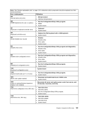
... (System board serial port 1 or 2 error) 1. System board 303 (Keyboard controller error) 1. Run the Configuration/Setup Utility program. 2. System board. 178X (Hard drive error, IDE only.) 1. Hard disk cables 2. Run the Configuration/Setup Utility program. 2. System board. 1602 (Cable for optional Remote Supervisor Adapter II not installed) v Disconnect all server and option power cords from server, wait 30 seconds, reconnect, and retry. 1762 (Hard drive configuration error, IDE only.) 1. Hard disk drive. 2. Optional microprocessor 289 (DIMM disabled by a field service...
... (System board serial port 1 or 2 error) 1. System board 303 (Keyboard controller error) 1. Run the Configuration/Setup Utility program. 2. System board. 178X (Hard drive error, IDE only.) 1. Hard disk cables 2. Run the Configuration/Setup Utility program. 2. System board. 1602 (Cable for optional Remote Supervisor Adapter II not installed) v Disconnect all server and option power cords from server, wait 30 seconds, reconnect, and retry. 1762 (Hard drive configuration error, IDE only.) 1. Hard disk drive. 2. Optional microprocessor 289 (DIMM disabled by a field service...
Hardware Maintenance Manual
Page 122
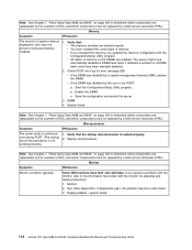
...Setup Utility program. Some IBM monitors have been manually disabled. 2. Verify that the startup microprocessor is not working properly.) 1. Enable the DIMM. System board. If you updated the memory configuration with the monitor for error message 289: v If the DIMM was disabled by the user or by a field service technician (FRU). If diagnostics pass, the problem may be replaced by a field service technician (FRU). Display adapter / system board. 112 xSeries 226 Type 8488 and 8648: Hardware Maintenance Manual and Troubleshooting Guide c. Note: See Chapter 7, "Parts listing...
...Setup Utility program. Some IBM monitors have been manually disabled. 2. Verify that the startup microprocessor is not working properly.) 1. Enable the DIMM. System board. If you updated the memory configuration with the monitor for error message 289: v If the DIMM was disabled by the user or by a field service technician (FRU). If diagnostics pass, the problem may be replaced by a field service technician (FRU). Display adapter / system board. 112 xSeries 226 Type 8488 and 8648: Hardware Maintenance Manual and Troubleshooting Guide c. Note: See Chapter 7, "Parts listing...
Hardware Maintenance Manual
Page 125
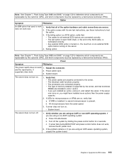
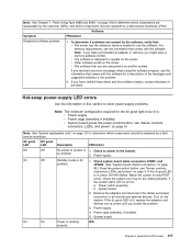
... replaced by a field service technician (FRU). If the failing option is a SCSI option, verify that: v The cables for all of the option hardware and cable connections are using an ACPI or non-ACPI operating system. The server does not turn on. 1. If the option comes with its own test instructions, use those instructions to -FRU index 115 Power Symptom FRU/action The power switch does not work . 2. v The type of the SCSI cable, is supported...
... replaced by a field service technician (FRU). If the failing option is a SCSI option, verify that: v The cables for all of the option hardware and cable connections are using an ACPI or non-ACPI operating system. The server does not turn on. 1. If the option comes with its own test instructions, use those instructions to -FRU index 115 Power Symptom FRU/action The power switch does not work . 2. v The type of the SCSI cable, is supported...
Hardware Maintenance Manual
Page 127
... good light to the problem. 2. If the dc good LED is working N/A properly. Symptom-to all internal and external devices. see "Server controls, connectors, LEDs, and power" on page 4. Remove the adapters and disconnect the cables and power connectors to -FRU index 117 For memory requirements, see the information that comes with the software. Watch the screen for any POST errors. v The software that you isolate the problem. 3. Power supply. 4. To determine if problems are using the software...
... good light to the problem. 2. If the dc good LED is working N/A properly. Symptom-to all internal and external devices. see "Server controls, connectors, LEDs, and power" on page 4. Remove the adapters and disconnect the cables and power connectors to -FRU index 117 For memory requirements, see the information that comes with the software. Watch the screen for any POST errors. v The software that you isolate the problem. 3. Power supply. 4. To determine if problems are using the software...
Hardware Maintenance Manual
Page 142
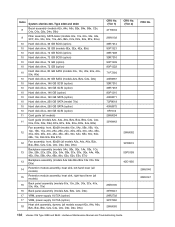
...xSeries 226, Type 8488 and 8648 8 Bezel assembly (models A2x, A4x, A6x, B2x, B4x, B6x, C2x, C4x, C6x, D2x, D4x, D6x) 9 Filler assembly, SATA bezel (models 00x, 10x, 20x, 30x, 32x, 3CY, 40x, 50x, 60x, 70x, A2x, B2x, C2x, D2x, E4x, EFx, EGx) 10 Hard disk drive, 36 GB SCSI (option) 10 Hard disk drive, 36 GB (models 0Ex, 3Ex, 4Ex, 80x) 10 Hard disk drive... 40K6875 9R7312 26K6094 39Y8442 26K6100 39Y8441 24R2702 39Y7260 26K6065 CRU No. (Tier 2) 26K6082 39Y8515 59P5159 42C1050 132 xSeries 226 Type 8488 and 8648: Hardware Maintenance Manual and Troubleshooting Guide FRU No. 26K6146 26K6147
...xSeries 226, Type 8488 and 8648 8 Bezel assembly (models A2x, A4x, A6x, B2x, B4x, B6x, C2x, C4x, C6x, D2x, D4x, D6x) 9 Filler assembly, SATA bezel (models 00x, 10x, 20x, 30x, 32x, 3CY, 40x, 50x, 60x, 70x, A2x, B2x, C2x, D2x, E4x, EFx, EGx) 10 Hard disk drive, 36 GB SCSI (option) 10 Hard disk drive, 36 GB (models 0Ex, 3Ex, 4Ex, 80x) 10 Hard disk drive... 40K6875 9R7312 26K6094 39Y8442 26K6100 39Y8441 24R2702 39Y7260 26K6065 CRU No. (Tier 2) 26K6082 39Y8515 59P5159 42C1050 132 xSeries 226 Type 8488 and 8648: Hardware Maintenance Manual and Troubleshooting Guide FRU No. 26K6146 26K6147
Hardware Maintenance Manual
Page 193
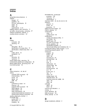
... drive activity LED 4 eject button 4 installing 36 © Copyright IBM Corp. 2004 CD-ROM drive (continued) problems 109 removing 70 specifications 3 channels, SCSI 40, 42, 45, 46, 51, 65 checkout general 11 power 21 procedure 12 CMOS recovery jumper 20 CMOS, clearing 19 components major 27 system board 85 configuration Configuration/Setup Utility 9 disk arrays 42 parallel port 64 PCI and PCI-X buses 51 server, updating 62 ServeRAID programs 9 ServerGuide Setup and Installation CD 9 Configuration/Setup Utility program 9, 10 connecting external options 62 connectors adapter 85 battery 85 cable...
... drive activity LED 4 eject button 4 installing 36 © Copyright IBM Corp. 2004 CD-ROM drive (continued) problems 109 removing 70 specifications 3 channels, SCSI 40, 42, 45, 46, 51, 65 checkout general 11 power 21 procedure 12 CMOS recovery jumper 20 CMOS, clearing 19 components major 27 system board 85 configuration Configuration/Setup Utility 9 disk arrays 42 parallel port 64 PCI and PCI-X buses 51 server, updating 62 ServeRAID programs 9 ServerGuide Setup and Installation CD 9 Configuration/Setup Utility program 9, 10 connecting external options 62 connectors adapter 85 battery 85 cable...

Hardware Maintenance Manual
Page 194
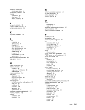
... 109 errors format, diagnostic code 15 hot-swap power supply 117 POST (ISPR) 121 SCSI 118 ServeRAID 119 service processor 118 Ethernet activity LED 5 cabling 64 connector 64 controller, messages 23 controller, troubleshooting 21 link status LED 5 external options, connecting 62 external SCSI connector 65 F fan connectors 86 front, removing 78 rear, removing 80 features and specifications, server 3 filler panel 38, 41 firmware, updating 20 flash update 18 front connectors 4 FRUs, defined iii, 131 H handle assembly, removing 95 handling static-sensitive devices 26 hard disk drive See also drive...
... 109 errors format, diagnostic code 15 hot-swap power supply 117 POST (ISPR) 121 SCSI 118 ServeRAID 119 service processor 118 Ethernet activity LED 5 cabling 64 connector 64 controller, messages 23 controller, troubleshooting 21 link status LED 5 external options, connecting 62 external SCSI connector 65 F fan connectors 86 front, removing 78 rear, removing 80 features and specifications, server 3 filler panel 38, 41 firmware, updating 20 flash update 18 front connectors 4 FRUs, defined iii, 131 H handle assembly, removing 95 handling static-sensitive devices 26 hard disk drive See also drive...
Hardware Maintenance Manual
Page 195
... 111 internal connectors 86 drive bays 37 drives, installing 36 J jumper, boot block 18 jumper, CMOS recovery 20 jumpers and switches 89 K keyboard problems 111 L LEDs CD-ROM 4 diskette drive 4 Ethernet 5 hard disk drive 4, 5 hard disk drive error 18 hard-disk drive 41 power supply 6 power-on 4 system board 17, 88 system error 4 lever, microprocessor socket 69 logs, error 13, 14 M major components 27 memory modules 35 installing 34 sequence of installation 34 specifications 3 memory problems 112 messages diagnostic 14 Ethernet controller 23 SCSI error 16 microprocessor air baffle, removing and...
... 111 internal connectors 86 drive bays 37 drives, installing 36 J jumper, boot block 18 jumper, CMOS recovery 20 jumpers and switches 89 K keyboard problems 111 L LEDs CD-ROM 4 diskette drive 4 Ethernet 5 hard disk drive 4, 5 hard disk drive error 18 hard-disk drive 41 power supply 6 power-on 4 system board 17, 88 system error 4 lever, microprocessor socket 69 logs, error 13, 14 M major components 27 memory modules 35 installing 34 sequence of installation 34 specifications 3 memory problems 112 messages diagnostic 14 Ethernet controller 23 SCSI error 16 microprocessor air baffle, removing and...


