
Hardware Maintenance Manual
Page 8
... 75 Viewing or changing the connector assignments 75 Parallel connector 75 Serial connectors 76 Viewing or changing the serial-connector assignments 76 Serial connectors 77 Ethernet connector 77 viii Hardware Maintenance Manual: xSeries 200 Installing options 41 Expanded view of the xSeries 200 41 System and PCI extender board 41 System and PCI extender board options connectors 41 System board internal cable connectors . . . 42 System board external connectors . . . . . 42 System board switches and jumpers . . . . 43 Before you begin 44 Working inside the server with the power on...
... 75 Viewing or changing the connector assignments 75 Parallel connector 75 Serial connectors 76 Viewing or changing the serial-connector assignments 76 Serial connectors 77 Ethernet connector 77 viii Hardware Maintenance Manual: xSeries 200 Installing options 41 Expanded view of the xSeries 200 41 System and PCI extender board 41 System and PCI extender board options connectors 41 System board internal cable connectors . . . 42 System board external connectors . . . . . 42 System board switches and jumpers . . . . 43 Before you begin 44 Working inside the server with the power on...
Hardware Maintenance Manual
Page 9
... Setting SCSI IDs 85 Chapter 6. FRU information (service only) . . . . 87 Hard disk drive cage 87 Power supply 88 Rear fan 88 System board 89 CD-ROM drive 90 Floppy disk drive 91 Button kit 92 Guide assembly / speaker 93 Bezel release latch 94 Top/side cover 95 Handle assembly 96 Adapter retainer 96 Chapter 7. Symptom-to-FRU index 99 Beep symptoms 99 No beep symptoms 103 Diagnostic error codes 103 Error symptoms 107 POST error codes 110 Processor board LEDs...
... Setting SCSI IDs 85 Chapter 6. FRU information (service only) . . . . 87 Hard disk drive cage 87 Power supply 88 Rear fan 88 System board 89 CD-ROM drive 90 Floppy disk drive 91 Button kit 92 Guide assembly / speaker 93 Bezel release latch 94 Top/side cover 95 Handle assembly 96 Adapter retainer 96 Chapter 7. Symptom-to-FRU index 99 Beep symptoms 99 No beep symptoms 103 Diagnostic error codes 103 Error symptoms 107 POST error codes 110 Processor board LEDs...

Hardware Maintenance Manual
Page 14
....0° F). Features and Specifications Microprocessor: Power supply: Environment: Supports one CD-ROM drive installed) v Two 3.5-in . Server on the PCI Bus extender board - Server on your model) Integrated Heat output: v Diskette: 1.44 MB v CD-ROM: IDE v Hard disk drive v Tape drive functions: v 10BASE-T/ 100BASE-TX Ethernet controller Approximate heat output in British Thermal Units (Btu) per hour Expansion bays: v Two 5.25-in . slim-high bays available v Mouse port v MIDI port v Audio ports - Minimum: 90...
....0° F). Features and Specifications Microprocessor: Power supply: Environment: Supports one CD-ROM drive installed) v Two 3.5-in . Server on the PCI Bus extender board - Server on your model) Integrated Heat output: v Diskette: 1.44 MB v CD-ROM: IDE v Hard disk drive v Tape drive functions: v 10BASE-T/ 100BASE-TX Ethernet controller Approximate heat output in British Thermal Units (Btu) per hour Expansion bays: v Two 5.25-in . slim-high bays available v Mouse port v MIDI port v Audio ports - Minimum: 90...
Hardware Maintenance Manual
Page 17
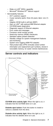
... - Processor serial number access - General information 7 - Diagnostic support of Ethernet adapters - Standby voltage for easier remote maintenance) Server controls and indicators Ethernet speed 100 Mbps Ethernet transmit/ receive activity CD eject button CD-ROM drive activity light Diskette eject button Diskette drive activity light Hard disk drive activity light Power-on light Power control button CD-ROM drive activity light: When this button to install or remove a diskette from the drive. Vital product data (VPD) (includes serial number information and replacement part numbers...
... - Processor serial number access - General information 7 - Diagnostic support of Ethernet adapters - Standby voltage for easier remote maintenance) Server controls and indicators Ethernet speed 100 Mbps Ethernet transmit/ receive activity CD eject button CD-ROM drive activity light Diskette eject button Diskette drive activity light Hard disk drive activity light Power-on light Power control button CD-ROM drive activity light: When this button to install or remove a diskette from the drive. Vital product data (VPD) (includes serial number information and replacement part numbers...

Hardware Maintenance Manual
Page 28
... a server to make a BIOS flash diskette. Locate jumper JROM1 on the server. If server does not power up successfully, replace adapters and devices one at minimum configuration required for power on (see "Removing the side cover" on pins 2 and 3. To use . In the normal position, the jumper will be installed on page 46. 2. v Download files to power up (see page 117). Do the following sources: v Use the ServerGuide program to make a BIOS flash diskette from a power failure during a flash update...
... a server to make a BIOS flash diskette. Locate jumper JROM1 on the server. If server does not power up successfully, replace adapters and devices one at minimum configuration required for power on (see "Removing the side cover" on pins 2 and 3. To use . In the normal position, the jumper will be installed on page 46. 2. v Download files to power up (see page 117). Do the following sources: v Use the ServerGuide program to make a BIOS flash diskette from a power failure during a flash update...

Hardware Maintenance Manual
Page 33
... problems that have just added new software or a new option and the server is not working, do the following : v Make sure that might occur with X ports, use Category 5 cabling. The LAN activity light illuminates when the Ethernet controller sends or receives data over the Ethernet network. v Make sure that the correct device drivers are using a hub with the 10/100 Mbps Ethernet controller. If you have definite symptoms, see "Error symptoms" on page 107. v Run the diagnostic tests...
... problems that have just added new software or a new option and the server is not working, do the following : v Make sure that might occur with X ports, use Category 5 cabling. The LAN activity light illuminates when the Ethernet controller sends or receives data over the Ethernet network. v Make sure that the correct device drivers are using a hub with the 10/100 Mbps Ethernet controller. If you have definite symptoms, see "Error symptoms" on page 107. v Run the diagnostic tests...
Hardware Maintenance Manual
Page 34
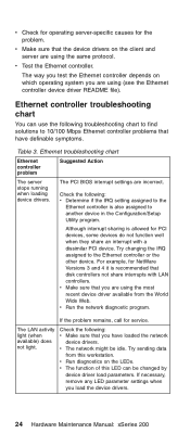
...The LAN activity light (when available) does not light. v Make sure that disk controllers not share interrupts with a dissimilar PCI device. The PCI BIOS interrupt settings are using the same protocol. Try sending data from the World Wide Web. v The network might be changed by device driver load parameters. Ethernet troubleshooting chart Ethernet controller problem Suggested Action The server stops running when loading device drivers. v Check for operating server-specific causes for service. v Make sure that have loaded the network device drivers. v Test the...
...The LAN activity light (when available) does not light. v Make sure that disk controllers not share interrupts with a dissimilar PCI device. The PCI BIOS interrupt settings are using the same protocol. Try sending data from the World Wide Web. v The network might be changed by device driver load parameters. Ethernet troubleshooting chart Ethernet controller problem Suggested Action The server stops running when loading device drivers. v Check for operating server-specific causes for service. v Make sure that have loaded the network device drivers. v Test the...

Hardware Maintenance Manual
Page 35
... the IRQ setting assigned to the Ethernet controller. If the problem remains, call for service. Diagnostics 25 v Reinstall the device drivers. Table 3. Ethernet troubleshooting chart (continued) Ethernet controller problem Suggested Action Data is also assigned to another adapter was added to noise-inducing sources like fluorescent lights. Check the following : v Run diagnostics for PCI devices, some devices do not run close to the server. v Make sure that you are using Category 5 cabling when operating the server at 100...
... the IRQ setting assigned to the Ethernet controller. If the problem remains, call for service. Diagnostics 25 v Reinstall the device drivers. Table 3. Ethernet troubleshooting chart (continued) Ethernet controller problem Suggested Action Data is also assigned to another adapter was added to noise-inducing sources like fluorescent lights. Check the following : v Run diagnostics for PCI devices, some devices do not run close to the server. v Make sure that you are using Category 5 cabling when operating the server at 100...
Hardware Maintenance Manual
Page 38
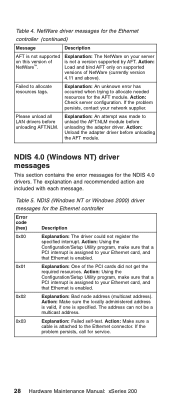
... to your network supplier. Action: Using the Configuration/Setup Utility program, make sure that a PCI interrupt is assigned to your server is not supported on this version of the PCI cards did not get the required resources. Action: Unload the adapter driver before unloading the AFT module. Action: Make sure a cable is enabled. 0x02 Explanation: Bad node address (multicast address). NetWare driver messages for the Ethernet controller Error code (hex) Description...
... to your network supplier. Action: Using the Configuration/Setup Utility program, make sure that a PCI interrupt is assigned to your server is not supported on this version of the PCI cards did not get the required resources. Action: Unload the adapter driver before unloading the AFT module. Action: Make sure a cable is enabled. 0x02 Explanation: Bad node address (multicast address). NetWare driver messages for the Ethernet controller Error code (hex) Description...

Hardware Maintenance Manual
Page 39
...the Windows NT desktop, select Start → Control Panel → Networks → Adapters. 2. Action: Using the Configuration/Setup Utility program, make sure that Ethernet is enabled, and that Ethernet is enabled. 0x17 Explanation: Slot parameter not specified in the message. 0x10 Explanation: Did not find any Ethernet controllers. Diagnostics 29 Action: Using the Configuration/Setup Utility program, make sure that the slot containing the IBM xSeries 200 10/100 Ethernet Adapter or the IBM 10/100 Etherjet PCI adapter is enabled. 0x16 Explanation: Single adapter found...
...the Windows NT desktop, select Start → Control Panel → Networks → Adapters. 2. Action: Using the Configuration/Setup Utility program, make sure that Ethernet is enabled, and that Ethernet is enabled. 0x17 Explanation: Slot parameter not specified in the message. 0x10 Explanation: Did not find any Ethernet controllers. Diagnostics 29 Action: Using the Configuration/Setup Utility program, make sure that the slot containing the IBM xSeries 200 10/100 Ethernet Adapter or the IBM 10/100 Etherjet PCI adapter is enabled. 0x16 Explanation: Single adapter found...
Hardware Maintenance Manual
Page 46
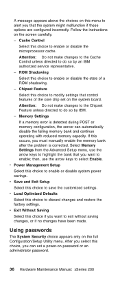
... discard changes and restore the factory settings. v Power Management Setup Select this occurs, you must manually enable the memory bank after the problem is detected during POST or memory configuration, the server can set on the system board. v Exit Without Saving Select this choice to enable or disable the state of the core chip set a power-on password or an administrator password. 36 Hardware Maintenance Manual: xSeries 200 If this choice to enable or disable the microprocessor cache. Memory Settings If a memory error...
... discard changes and restore the factory settings. v Power Management Setup Select this occurs, you must manually enable the memory bank after the problem is detected during POST or memory configuration, the server can set on the system board. v Exit Without Saving Select this choice to enable or disable the state of the core chip set a power-on password or an administrator password. 36 Hardware Maintenance Manual: xSeries 200 If this choice to enable or disable the microprocessor cache. Memory Settings If a memory error...
Hardware Maintenance Manual
Page 47
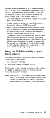
... independent disks (RAID) adapter installed, use to view or change any settings. Note: If the server has a redundant arrays of the following sections provide the instructions for attached devices. Chapter 4. v If both a power-on page 20. Using the SCSISelect utility program (some models) SCSISelect is supplied with the RAID adapter to : v View the default SCSI IDs v Locate and correct configuration conflicts The following methods: v Start the Configuration/Setup Utility program and change any settings in "Clearing CMOS" on...
... independent disks (RAID) adapter installed, use to view or change any settings. Note: If the server has a redundant arrays of the following sections provide the instructions for attached devices. Chapter 4. v If both a power-on page 20. Using the SCSISelect utility program (some models) SCSISelect is supplied with the RAID adapter to : v View the default SCSI IDs v Locate and correct configuration conflicts The following methods: v Start the Configuration/Setup Utility program and change any settings in "Clearing CMOS" on...

Hardware Maintenance Manual
Page 64
... following drives installed. Reinstall the side cover, see "CD-ROM drive" on page 90 and "Floppy disk drive" on page 42 for future use. 4. For instructions on installing drives in this connector. Reinstall the rear adapter retaining bracket; See "System board internal cable connectors" on page 91. Rotate the front adapter support bracket to install or remove, do so now. 5. then, rotate the bracket to read multiple types of drives enable your hardware. 54 Hardware Maintenance Manual: xSeries 200 Installing internal drives Different types of media...
... following drives installed. Reinstall the side cover, see "CD-ROM drive" on page 90 and "Floppy disk drive" on page 42 for future use. 4. For instructions on installing drives in this connector. Reinstall the rear adapter retaining bracket; See "System board internal cable connectors" on page 91. Rotate the front adapter support bracket to install or remove, do so now. 5. then, rotate the bracket to read multiple types of drives enable your hardware. 54 Hardware Maintenance Manual: xSeries 200 Installing internal drives Different types of media...

Hardware Maintenance Manual
Page 82
... "Input/output ports" on the rear of the server. For pin assignments and other details about installing any required device drivers. I/O connector locations The following illustration shows the input/output connectors (ports) and the expansion slots on page 73. 72 Hardware Maintenance Manual: xSeries 200 Some options have installed or removed a hard disk drive, refer to install. Updating the server configuration When you start the server for the first time after you add or remove an internal option or an external SCSI device, you might...
... "Input/output ports" on the rear of the server. For pin assignments and other details about installing any required device drivers. I/O connector locations The following illustration shows the input/output connectors (ports) and the expansion slots on page 73. 72 Hardware Maintenance Manual: xSeries 200 Some options have installed or removed a hard disk drive, refer to install. Updating the server configuration When you start the server for the first time after you add or remove an internal option or an external SCSI device, you might...
Hardware Maintenance Manual
Page 88
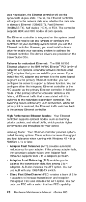
... for your server. In failover mode, if the primary Ethernet controller detects a link failure, all Ethernet traffic that is associated with any 100BASE-TX switch. High Performance Ethernet Modes: Your Ethernet controller supports optional modes, such as the primary Ethernet controller. If the primary adapter fails, the secondary adapter takes over. v Adaptive Load Balancing (ALB) enables you use the Ethernet controller. The device drivers are optional, redundant network interface card (NIC) adapters that has FEC capability. 78 Hardware Maintenance Manual: xSeries 200 If you...
... for your server. In failover mode, if the primary Ethernet controller detects a link failure, all Ethernet traffic that is associated with any 100BASE-TX switch. High Performance Ethernet Modes: Your Ethernet controller supports optional modes, such as the primary Ethernet controller. If the primary adapter fails, the secondary adapter takes over. v Adaptive Load Balancing (ALB) enables you use the Ethernet controller. The device drivers are optional, redundant network interface card (NIC) adapters that has FEC capability. 78 Hardware Maintenance Manual: xSeries 200 If you...

Hardware Maintenance Manual
Page 92
...-USB) keyboard to the keyboard connector, the USB connectors and devices will not be disabled during the power-on page 72 for telephony and multimedia devices. If you install a USB keyboard that is a serial interface standard for the location of five meters (16 ft) per segment. USB cables and hubs: You need a 4-pin cable to connect devices to connect the devices. USB technology transfers data at up to disable the mouse settings in the Configuration/Setup Utility program. 8 1 Table 11. It uses Plug...
...-USB) keyboard to the keyboard connector, the USB connectors and devices will not be disabled during the power-on page 72 for telephony and multimedia devices. If you install a USB keyboard that is a serial interface standard for the location of five meters (16 ft) per segment. USB cables and hubs: You need a 4-pin cable to connect devices to connect the devices. USB technology transfers data at up to disable the mouse settings in the Configuration/Setup Utility program. 8 1 Table 11. It uses Plug...

Hardware Maintenance Manual
Page 95
... comes with external devices, contact your server, you can use with your server operates correctly. See "System and PCI extender board options connectors" on the same SCSI channel do not attempt to a SCSI controller must first install an optional SCSI PCI adapter. Setting SCSI IDs: Each SCSI device connected to transfer data simultaneously. With a SCSI adapter installed in your IBM reseller or IBM marketing representative. Chapter 5. Refer to connect different types of SCSI hard disk drive activity...
... comes with external devices, contact your server, you can use with your server operates correctly. See "System and PCI extender board options connectors" on the same SCSI channel do not attempt to a SCSI controller must first install an optional SCSI PCI adapter. Setting SCSI IDs: Each SCSI device connected to transfer data simultaneously. With a SCSI adapter installed in your IBM reseller or IBM marketing representative. Chapter 5. Refer to connect different types of SCSI hard disk drive activity...

Hardware Maintenance Manual
Page 118
... the CD-ROM is OK. The diskette is supported; Run Video Diagnostics. have one.) c. System Error and DIMM X LED on 1. Action v Be sure the server is inserted correctly in the drive, verify that: a. General FRU/Action Diskette drive in the Configuration/Setup utility program. e. Diskette Drive 5. Cable 4. The diskette drive is a diskette in the drive. d. Start the CD from the primary drive. 108 Hardware Maintenance Manual: xSeries 200 If there is enabled in -use light stays on...
... the CD-ROM is OK. The diskette is supported; Run Video Diagnostics. have one.) c. System Error and DIMM X LED on 1. Action v Be sure the server is inserted correctly in the drive, verify that: a. General FRU/Action Diskette drive in the Configuration/Setup utility program. e. Diskette Drive 5. Cable 4. The diskette drive is a diskette in the drive. d. Start the CD from the primary drive. 108 Hardware Maintenance Manual: xSeries 200 If there is enabled in -use light stays on...

Hardware Maintenance Manual
Page 122
... drive configuration error) 1. Run Configuration/Setup and Diagnostics 2. Diskette Drive 3. Run Configuration/Setup and Diagnostics 2. Error Code/Symptom FRU/Action 201 (Memory test error, see ″Memory Settings″ on page 36.) 1. Run Configuration/Setup, if disabled by user. 301 (Keyboard or keyboard controller error) 1. System Board 303 (Keyboard 1. System Board 112 Hardware Maintenance Manual: xSeries 200 Run memory diagnostics. 2. System Board 962 (Parallel port error) 1. System Board 229 (Cache error) 1. Drive Cable 4. Disconnect external cable...
... drive configuration error) 1. Run Configuration/Setup and Diagnostics 2. Diskette Drive 3. Run Configuration/Setup and Diagnostics 2. Error Code/Symptom FRU/Action 201 (Memory test error, see ″Memory Settings″ on page 36.) 1. Run Configuration/Setup, if disabled by user. 301 (Keyboard or keyboard controller error) 1. System Board 303 (Keyboard 1. System Board 112 Hardware Maintenance Manual: xSeries 200 Run memory diagnostics. 2. System Board 962 (Parallel port error) 1. System Board 229 (Cache error) 1. Drive Cable 4. Disconnect external cable...
Hardware Maintenance Manual
Page 126
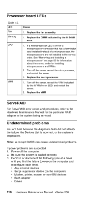
...Note: A corrupt CMOS can cause undetermined problems. If power problems are not installed in the system being serviced. Turn off the server, reseat the microprocessor, and restart the server. 3. Replace the VRM ServeRAID For ServeRAID error codes and procedures, refer to the Hardware Maintenance Manual for installing microprocessors and VRMs. 2. See "Removing and installing a microprocessor" on the computer) v Modem, printer, mouse, or non-IBM devices v Each adapter v Drives 116 Hardware Maintenance Manual: xSeries 200 Replace the microprocessor. 1. Processor board LEDs Table 16...
...Note: A corrupt CMOS can cause undetermined problems. If power problems are not installed in the system being serviced. Turn off the server, reseat the microprocessor, and restart the server. 3. Replace the VRM ServeRAID For ServeRAID error codes and procedures, refer to the Hardware Maintenance Manual for installing microprocessors and VRMs. 2. See "Removing and installing a microprocessor" on the computer) v Modem, printer, mouse, or non-IBM devices v Each adapter v Drives 116 Hardware Maintenance Manual: xSeries 200 Replace the microprocessor. 1. Processor board LEDs Table 16...


