Manual
Page 4
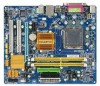
......6 GA-EG31M-S2 Motherboard Layout 7 Block Diagram...8 Chapter 1 Hardware Installation 9 1-1 Installation Precautions 9 1-2 Product Specifications 10 1-3 Installing the CPU and CPU Cooler 12 1-3-1 Installing the CPU 12 1-3-2 Installing the CPU Cooler 14 1-4-1 Dual Channel Memory Configuration 15 1-4 Installing the Memory 15 1-4-2 Installing a Memory 16 1-5 Installing an Expansion Card 17 1-6 Back Panel Connectors 18 1-7 Internal Connectors 20 Chapter 2 BIOS Setup 31 2-1 Startup Screen 32 2-2 The Main Menu 33 2-3 Standard CMOS Features 35 2-4 Advanced BIOS Features...
......6 GA-EG31M-S2 Motherboard Layout 7 Block Diagram...8 Chapter 1 Hardware Installation 9 1-1 Installation Precautions 9 1-2 Product Specifications 10 1-3 Installing the CPU and CPU Cooler 12 1-3-1 Installing the CPU 12 1-3-2 Installing the CPU Cooler 14 1-4-1 Dual Channel Memory Configuration 15 1-4 Installing the Memory 15 1-4-2 Installing a Memory 16 1-5 Installing an Expansion Card 17 1-6 Back Panel Connectors 18 1-7 Internal Connectors 20 Chapter 2 BIOS Setup 31 2-1 Startup Screen 32 2-2 The Main Menu 33 2-3 Standard CMOS Features 35 2-4 Advanced BIOS Features...
Manual
Page 10
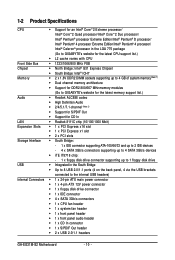
... in the South Bridge Š Up to 8 USB 2.0/1.1 ports (4 on the back panel, 4 via the USB brackets connected to the internal USB headers) Internal Connectors Š 1 x 24-pin ATX main power connector Š 1 x 4-pin ATX 12V power connector Š 1 x floppy disk drive connector Š 1 x IDE connector Š 4 x SATA 3Gb/s connectors Š 1 x CPU fan header Š 1 x system fan header Š 1 x front panel header Š 1 x front panel audio header Š 1 x CD In connector Š 1 x S/PDIF Out header Š 2 x USB 2.0/1.1 headers GA-EG31M-S2 Motherboard - 10 -
... in the South Bridge Š Up to 8 USB 2.0/1.1 ports (4 on the back panel, 4 via the USB brackets connected to the internal USB headers) Internal Connectors Š 1 x 24-pin ATX main power connector Š 1 x 4-pin ATX 12V power connector Š 1 x floppy disk drive connector Š 1 x IDE connector Š 4 x SATA 3Gb/s connectors Š 1 x CPU fan header Š 1 x system fan header Š 1 x front panel header Š 1 x front panel audio header Š 1 x CD In connector Š 1 x S/PDIF Out header Š 2 x USB 2.0/1.1 headers GA-EG31M-S2 Motherboard - 10 -
Manual
Page 15
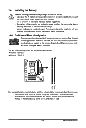
... motherboard supports the memory. The two DDR2 memory sockets are unable to install the memory: • Make sure that memory of the same capacity, brand, speed, and chips be enabled if only one direction. It is installed, the BIOS will double the original memory bandwidth. If you begin to insert the memory, switch the direction. 1-4-1 Dual Channel Memory Configuration This motherboard provides two DDR2 memory sockets and supports Dual Channel Technology. A memory module can be used . - 15 - Hardware Installation 1-4 Installing the Memory...
... motherboard supports the memory. The two DDR2 memory sockets are unable to install the memory: • Make sure that memory of the same capacity, brand, speed, and chips be enabled if only one direction. It is installed, the BIOS will double the original memory bandwidth. If you begin to insert the memory, switch the direction. 1-4-1 Dual Channel Memory Configuration This motherboard provides two DDR2 memory sockets and supports Dual Channel Technology. A memory module can be used . - 15 - Hardware Installation 1-4 Installing the Memory...
Manual
Page 17
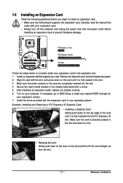
... read the manual that supports your card. Example: Installing and Removing a PCI Express x16 Graphics Card: • Installing a Graphics Card: Gently push down on the card are completely inserted into the PCI Express x16 slot. Locate an expansion slot that came with the expansion card in your operating system. After installing all expansion cards, replace the chassis cover(s). 6. Install the driver provided with your expansion card. • Always turn off the computer and unplug the power cord from...
... read the manual that supports your card. Example: Installing and Removing a PCI Express x16 Graphics Card: • Installing a Graphics Card: Gently push down on the card are completely inserted into the PCI Express x16 slot. Locate an expansion slot that came with the expansion card in your operating system. After installing all expansion cards, replace the chassis cover(s). 6. Install the driver provided with your expansion card. • Always turn off the computer and unplug the power cord from...
Manual
Page 22
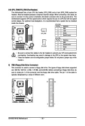
... (Fan Headers) The motherboard has a 4-pin CPU fan header (CPU_FAN) and a 4-pin (SYS_FAN) system fan headers. The motherboard supports CPU fan speed control, which requires the use of different color. 34 33 GA-EG31M-S2 Motherboard 2 1 - 22 - For optimum heat dissipation, it in damage to the CPU or the system may result in the correct orientation (the black connector wire is used to connect it is typically designated by a stripe of a CPU fan with fan speed control design. Do not place a jumper...
... (Fan Headers) The motherboard has a 4-pin CPU fan header (CPU_FAN) and a 4-pin (SYS_FAN) system fan headers. The motherboard supports CPU fan speed control, which requires the use of different color. 34 33 GA-EG31M-S2 Motherboard 2 1 - 22 - For optimum heat dissipation, it in damage to the CPU or the system may result in the correct orientation (the black connector wire is used to connect it is typically designated by a stripe of a CPU fan with fan speed control design. Do not place a jumper...
Manual
Page 24
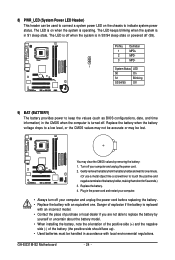
... power status. The LED is on the chassis to replace the battery by removing the battery: 1. Danger of explosion if the battery is in S3/S4 sleep state or powered off your computer. • Always turn off (S5). 8) PWR_LED (System Power LED Header) This header can be used to connect a system power LED on when the system is in S1 sleep state. The LED keeps blinking when the system is operating. GA-EG31M-S2 Motherboard...
... power status. The LED is on the chassis to replace the battery by removing the battery: 1. Danger of explosion if the battery is in S3/S4 sleep state or powered off your computer. • Always turn off (S5). 8) PWR_LED (System Power LED Header) This header can be used to connect a system power LED on when the system is in S1 sleep state. The LED keeps blinking when the system is operating. GA-EG31M-S2 Motherboard...
Manual
Page 26
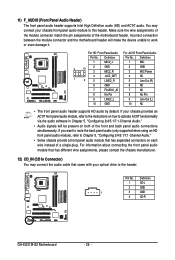
... audio software in Chapter 5, "Configuring 2/4/5.1/7.1-Channel Audio." • Audio signals will make the device unable to work or even damage it. Pin No. You may connect the audio cable that has separated connectors on both of the motherboard header. Definition 1 CD-L 2 GND 1 3 GND 4 CD-R GA-EG31M-S2 Motherboard - 26 - If you want to mute the back panel audio (only supported when using an HD front panel audio module), refer to Chapter 5, "Configuring 2/4/5.1/7.1-Channel Audio." • Some chassis provide a front panel audio...
... audio software in Chapter 5, "Configuring 2/4/5.1/7.1-Channel Audio." • Audio signals will make the device unable to work or even damage it. Pin No. You may connect the audio cable that has separated connectors on both of the motherboard header. Definition 1 CD-L 2 GND 1 3 GND 4 CD-R GA-EG31M-S2 Motherboard - 26 - If you want to mute the back panel audio (only supported when using an HD front panel audio module), refer to Chapter 5, "Configuring 2/4/5.1/7.1-Channel Audio." • Some chassis provide a front panel audio...
Manual
Page 29
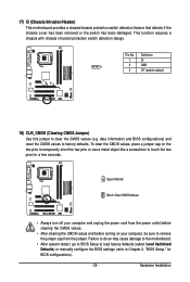
... unplug the power cord from the jumper. Pin No. date information and BIOS configurations) and reset the CMOS values to remove the jumper cap from the power outlet before clearing the CMOS values. • After clearing the CMOS values and before turning on the two pins to temporarily short the two pins or use a metal object like a screwdriver to clear the CMOS values (e.g. 17) CI (Chassis Intrusion Header) This motherboard provides a chassis/chassis protection switch detection feature...
... unplug the power cord from the jumper. Pin No. date information and BIOS configurations) and reset the CMOS values to remove the jumper cap from the power outlet before clearing the CMOS values. • After clearing the CMOS values and before turning on the two pins to temporarily short the two pins or use a metal object like a screwdriver to clear the CMOS values (e.g. 17) CI (Chassis Intrusion Header) This motherboard provides a chassis/chassis protection switch detection feature...
Manual
Page 31
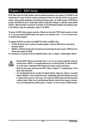
... advanced BIOS Setup menu options, you do it is turned on using the current version of the battery/clearing CMOS jumper in the CMOS. For instructions on . Inadequate BIOS flashing may result in system malfunction. • BIOS will emit a beep code during the POST. If this occurs, try to clear the CMOS values and reset the board to default values. (Refer to the "Load Optimized Defaults" section in the CMOS on the motherboard supplies the necessary power to the CMOS to...
... advanced BIOS Setup menu options, you do it is turned on using the current version of the battery/clearing CMOS jumper in the CMOS. For instructions on . Inadequate BIOS flashing may result in system malfunction. • BIOS will emit a beep code during the POST. If this occurs, try to clear the CMOS values and reset the board to default values. (Refer to the "Load Optimized Defaults" section in the CMOS on the motherboard supplies the necessary power to the CMOS to...
Manual
Page 34
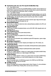
....) „ Exit Without Saving Abandon all the power-saving functions. „ PnP/PCI Configurations Use this menu to configure the system's PCI & PnP resources. „ PC Health Status Use this menu to see information about autodetected system/CPU temperature, system voltage and fan speed, etc. „ MB Intelligent Tweaker(M.I.T.) Use this menu to configure all changes and the previous settings remain in BIOS Setup. „ Set User Password Change, set , or disable password. You can use this task.) GA-EG31M-S2 Motherboard - 34 -
....) „ Exit Without Saving Abandon all the power-saving functions. „ PnP/PCI Configurations Use this menu to configure the system's PCI & PnP resources. „ PC Health Status Use this menu to see information about autodetected system/CPU temperature, system voltage and fan speed, etc. „ MB Intelligent Tweaker(M.I.T.) Use this menu to configure all changes and the previous settings remain in BIOS Setup. „ Set User Password Change, set , or disable password. You can use this task.) GA-EG31M-S2 Motherboard - 34 -
Manual
Page 35
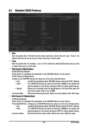
... manually enter the specifications of the device during the POST for faster system startup. For example, 1 p.m. BIOS Setup IDE Channel 0 Master/Slave IDE HDD Auto-Detection Press to CHS. Access Mode Sets the hard drive access mode. Options are : Auto (default), CHS, LBA, Large. Select the desired field and use the up arrow or down arrow key to None so the system will skip the detection of the hard drive when the hard drive access mode is set the time. Sets the hard drive access mode. IDE Channel...
... manually enter the specifications of the device during the POST for faster system startup. For example, 1 p.m. BIOS Setup IDE Channel 0 Master/Slave IDE HDD Auto-Detection Press to CHS. Access Mode Sets the hard drive access mode. Options are : Auto (default), CHS, LBA, Large. Select the desired field and use the up arrow or down arrow key to None so the system will skip the detection of the hard drive when the hard drive access mode is set the time. Sets the hard drive access mode. IDE Channel...
Manual
Page 37
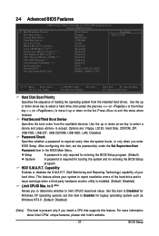
... features, please visit Intel's website. - 37 - After configuring this item, set this feature. This feature allows your hard drive. BIOS Setup Capability Limit CPUID Max. to 3 (Note) No-Execute Memory Protect (Note) CPU Enhanced Halt (C1E) (Note) CPU Thermal Monitor 2(TM2) (Note) CPU EIST Function (Note) Virtualization Technology (Note) Init Display First Onboard VGA On-Chip Frame Buffer Size [Press Enter] [Floppy] [Hard Disk] [CDROM] [Setup] [Disabled] [Disabled] [Enabled] [Enabled] [Enabled] [Enabled] [Enabled] [PCI] [Enable If No Ext PEG] [8MB+1~2MB for GTT...
... features, please visit Intel's website. - 37 - After configuring this item, set this feature. This feature allows your hard drive. BIOS Setup Capability Limit CPUID Max. to 3 (Note) No-Execute Memory Protect (Note) CPU Enhanced Halt (C1E) (Note) CPU Thermal Monitor 2(TM2) (Note) CPU EIST Function (Note) Virtualization Technology (Note) Init Display First Onboard VGA On-Chip Frame Buffer Size [Press Enter] [Floppy] [Hard Disk] [CDROM] [Setup] [Disabled] [Disabled] [Enabled] [Enabled] [Enabled] [Enabled] [Enabled] [PCI] [Enable If No Ext PEG] [8MB+1~2MB for GTT...
Manual
Page 38
... voltage will use only this item to decrease average power consumption and heat production. (Default: Enabled) Virtualization Technology (Note) Enables or disables Intel® Virtualization Technology. PCI Sets the PCI graphics card as the first display. (Default) Onboard Sets the onboard VGA as the first display. If you install a CPU that supports this feature. GA-EG31M-S2 Motherboard - 38 - Depending on CPU loading, Intel® EIST technology can function as multiple virtual systems. (Default: Enabled) Init Display First Specifies the first initiation of system memory...
... voltage will use only this item to decrease average power consumption and heat production. (Default: Enabled) Virtualization Technology (Note) Enables or disables Intel® Virtualization Technology. PCI Sets the PCI graphics card as the first display. (Default) Onboard Sets the onboard VGA as the first display. If you install a CPU that supports this feature. GA-EG31M-S2 Motherboard - 38 - Depending on CPU loading, Intel® EIST technology can function as multiple virtual systems. (Default: Enabled) Init Display First Specifies the first initiation of system memory...
Manual
Page 39
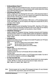
...SATA mode. Non-Combined Sets all SATA devices to Combined or Enhanced mode. Ch.0 Master/Slave Sets the IDE channels to Ch. 0 Master/Slave. (Default) Ch.1 Master/Slave Sets the IDE channels to USB Controller USB 2.0 Controller USB Keyboard Support USB Mouse Support Legacy USB storage detect Azalia Codec Onboard H/W LAN ` SMART LAN Onboard LAN Boot ROM Onboard Serial Port 1 Onboard Serial Port 2 Onboard Parallel Port Parallel Port Mode [Enabled] [Auto] Ch.0 Master/Slave Ch.2 Master/Slave Ch.3 Master/Slave [Enabled] [Enabled] [Disabled] [Disabled] [Enabled] [Auto] [Enabled] [Press Enter...
...SATA mode. Non-Combined Sets all SATA devices to Combined or Enhanced mode. Ch.0 Master/Slave Sets the IDE channels to Ch. 0 Master/Slave. (Default) Ch.1 Master/Slave Sets the IDE channels to USB Controller USB 2.0 Controller USB Keyboard Support USB Mouse Support Legacy USB storage detect Azalia Codec Onboard H/W LAN ` SMART LAN Onboard LAN Boot ROM Onboard Serial Port 1 Onboard Serial Port 2 Onboard Parallel Port Parallel Port Mode [Enabled] [Auto] Ch.0 Master/Slave Ch.2 Master/Slave Ch.3 Master/Slave [Enabled] [Enabled] [Disabled] [Disabled] [Enabled] [Auto] [Enabled] [Press Enter...
Manual
Page 40
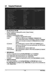
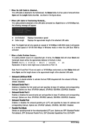
... the On-Chip SATA Mode and PATA IDE Set to detect the status of the USB functionalities below. Refer to the fault or short. This feature will detect cabling issue and report the approximate distance to the following information for diagnosing your LAN cable: GA-EG31M-S2 Motherboard - 40 - Onboard H/W LAN Enables or disables the onboard LAN function. (Default: Enabled) If you wish to install a 3rd party add-in network card instead of using the onboard LAN, set this...
... the On-Chip SATA Mode and PATA IDE Set to detect the status of the USB functionalities below. Refer to the fault or short. This feature will detect cabling issue and report the approximate distance to the following information for diagnosing your LAN cable: GA-EG31M-S2 Motherboard - 40 - Onboard H/W LAN Enables or disables the onboard LAN function. (Default: Enabled) If you wish to install a 3rd party add-in network card instead of using the onboard LAN, set this...
Manual
Page 41
... used in Windows mode or when the LAN Boot ROM is detected on Part 1-2. Options are : 378/IRQ7 (default), 278/IRQ5, 3BC/IRQ7, Disabled. Onboard Parallel Port Enables or disables the onboard parallel port (LPT) and specifies its base I /O address and corresponding interrupt. When a Cable Problem Occurs... Note: The Gigabit hub will appear: Start detecting at about 2m on the LAN cable connected to activate the boot ROM integrated with the onboard LAN chip. (Default: Disabled) Onboard Serial Port 1 Enables or disables the first serial port...
... used in Windows mode or when the LAN Boot ROM is detected on Part 1-2. Options are : 378/IRQ7 (default), 278/IRQ5, 3BC/IRQ7, Disabled. Onboard Parallel Port Enables or disables the onboard parallel port (LPT) and specifies its base I /O address and corresponding interrupt. When a Cable Problem Occurs... Note: The Gigabit hub will appear: Start detecting at about 2m on the LAN cable connected to activate the boot ROM integrated with the onboard LAN chip. (Default: Disabled) Onboard Serial Port 1 Enables or disables the first serial port...
Manual
Page 47
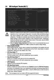
... present only if a CPU with unlocked clock ratio is recommended that supports this occurs, clear the CMOS values and reset the board to CPU, chipset, or memory and reduce the useful life of CPU host clock. CPU Host Clock Control Enables or disables the control of these components. BIOS Setup Incorrectly doing overclock/overvoltage may result in red, it is installed. Auto allows the BIOS to enhance the performance of the graphics chip and memory. mode based on your...
... present only if a CPU with unlocked clock ratio is recommended that supports this occurs, clear the CMOS values and reset the board to CPU, chipset, or memory and reduce the useful life of CPU host clock. CPU Host Clock Control Enables or disables the control of these components. BIOS Setup Incorrectly doing overclock/overvoltage may result in red, it is installed. Auto allows the BIOS to enhance the performance of the graphics chip and memory. mode based on your...
Manual
Page 53
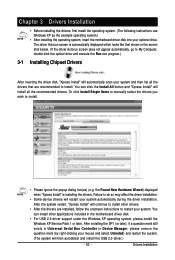
... in Universal Serial Bus Controller in Device Manager, please remove the question mark (by right-clicking your mouse and select Uninstall) and restart the system. (The system will install all the drivers that shown in the motherboard driver disk. • For USB 2.0 driver support under the Windows XP operating system, please install the Windows XP Service Pack 1 or later. You can install other drivers. • After the drivers are recommended...
... in Universal Serial Bus Controller in Device Manager, please remove the question mark (by right-clicking your mouse and select Uninstall) and restart the system. (The system will install all the drivers that shown in the motherboard driver disk. • For USB 2.0 driver support under the Windows XP operating system, please install the Windows XP Service Pack 1 or later. You can install other drivers. • After the drivers are recommended...
Manual
Page 70
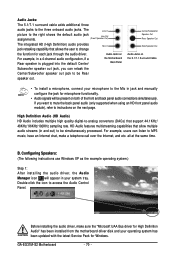
... that allows the user to change the function for Windows. GA-EG31M-S2 Motherboard - 70 - Audio Jacks on For example, in your operating system has been updated with the latest Service Pack for each jack through the audio driver. Configuring Speakers: (The following instructions use Windows XP as the example operating system.) Step 1: After installing the audio driver, the Audio Manager icon will be simultaneously processed. Before installing the audio driver, make a telephone call...
... that allows the user to change the function for Windows. GA-EG31M-S2 Motherboard - 70 - Audio Jacks on For example, in your operating system has been updated with the latest Service Pack for each jack through the audio driver. Configuring Speakers: (The following instructions use Windows XP as the example operating system.) Step 1: After installing the audio driver, the Audio Manager icon will be simultaneously processed. Before installing the audio driver, make a telephone call...
Manual
Page 77
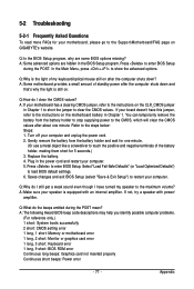
...: System boots successfully 2 short: CMOS setting error 1 long, 1 short: Memory or motherboard error 1 long, 2 short: Monitor or graphics card error 1 long, 3 short: Keyboard error 1 long, 9 short: BIOS ROM error Continuous long beeps: Graphics card not inserted properly Continuous short beeps: Power error - 77 - Q:How do I still get a weak sound even though I clear the CMOS values? A: If your computer. 5. Replace the battery. 4. Q:What do the beeps emitted during the POST. Plug in the power cord and restart your motherboard has a clearing CMOS jumper, refer to the instructions on...
...: System boots successfully 2 short: CMOS setting error 1 long, 1 short: Memory or motherboard error 1 long, 2 short: Monitor or graphics card error 1 long, 3 short: Keyboard error 1 long, 9 short: BIOS ROM error Continuous long beeps: Graphics card not inserted properly Continuous short beeps: Power error - 77 - Q:How do I still get a weak sound even though I clear the CMOS values? A: If your computer. 5. Replace the battery. 4. Q:What do the beeps emitted during the POST. Plug in the power cord and restart your motherboard has a clearing CMOS jumper, refer to the instructions on...


