Manual
Page 3
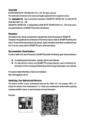
... to the specifications and features in this manual may be reproduced, copied, translated, transmitted, or published in the use GIGABYTE's unique features, read or download the information on/from the Support\Motherboard\Technology Guide page on our website. sive global... product information, carefully read the User's Manual. „ For instructions on your motherboard revision before updating motherboard BIOS, drivers, or when looking for technical information. GIGABYTE UNITED INC. The logo is designated by any means without prior notice. For example, "REV: 1.0" means ...
... to the specifications and features in this manual may be reproduced, copied, translated, transmitted, or published in the use GIGABYTE's unique features, read or download the information on/from the Support\Motherboard\Technology Guide page on our website. sive global... product information, carefully read the User's Manual. „ For instructions on your motherboard revision before updating motherboard BIOS, drivers, or when looking for technical information. GIGABYTE UNITED INC. The logo is designated by any means without prior notice. For example, "REV: 1.0" means ...
Manual
Page 4
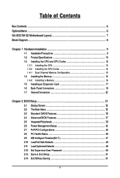
Table of Contents Box Contents ...6 OptionalItems...6 GA-EG31M-S2 Motherboard Layout 7 Block Diagram...8 Chapter 1 Hardware Installation 9 1-1 Installation Precautions 9 1-2 Product Specifications 10 1-3 Installing the CPU and CPU Cooler 12 ... Memory 16 1-5 Installing an Expansion Card 17 1-6 Back Panel Connectors 18 1-7 Internal Connectors 20 Chapter 2 BIOS Setup 31 2-1 Startup Screen 32 2-2 The Main Menu 33 2-3 Standard CMOS Features 35 2-4 Advanced BIOS Features 37 2-5 IntegratedPeripherals 39 2-6 Power Management Setup 42 2-7 PnP/PCI Configurations 44 2-8 PC Health Status ...
Table of Contents Box Contents ...6 OptionalItems...6 GA-EG31M-S2 Motherboard Layout 7 Block Diagram...8 Chapter 1 Hardware Installation 9 1-1 Installation Precautions 9 1-2 Product Specifications 10 1-3 Installing the CPU and CPU Cooler 12 ... Memory 16 1-5 Installing an Expansion Card 17 1-6 Back Panel Connectors 18 1-7 Internal Connectors 20 Chapter 2 BIOS Setup 31 2-1 Startup Screen 32 2-2 The Main Menu 33 2-3 Standard CMOS Features 35 2-4 Advanced BIOS Features 37 2-5 IntegratedPeripherals 39 2-6 Power Management Setup 42 2-7 PnP/PCI Configurations 44 2-8 PC Health Status ...
Manual
Page 5
... 54 3-3 Technical Manuals 54 3-4 Contact ...55 3-5 System ...55 3-6 Download Center 56 Chapter 4 Unique Features 57 4-1 Xpress Recovery2 57 4-2 BIOS Update Utilities 62 4-2-1 Updating the BIOS with the Q-Flash Utility 62 4-2-2 Updating the BIOS with the @BIOS Utility 65 4-3 EasyTune 5 Pro 66 4-4 Dynamic Energy Saver Advanced 67 Chapter 5 Appendix ...69 5-1 Configuring Audio Input and Output...
... 54 3-3 Technical Manuals 54 3-4 Contact ...55 3-5 System ...55 3-6 Download Center 56 Chapter 4 Unique Features 57 4-1 Xpress Recovery2 57 4-2 BIOS Update Utilities 62 4-2-1 Updating the BIOS with the Q-Flash Utility 62 4-2-2 Updating the BIOS with the @BIOS Utility 65 4-3 EasyTune 5 Pro 66 4-4 Dynamic Energy Saver Advanced 67 Chapter 5 Appendix ...69 5-1 Configuring Audio Input and Output...
Manual
Page 8
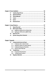
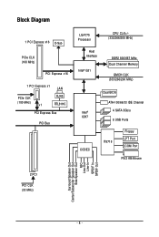
Block Diagram 1 PCI Express x16 D-Sub PCIe CLK (100 MHz) PCI Express x16 1 PCI Express x1 LAN PCIe CLK (100 MHz) x1 RJ45 RTL8111C PCI Express Bus PCI Bus LGA775 Processor Host Interface Intel® G31 CPU CLK+/(333/266/200 MHz) DDR2 800/667 MHz Dual Channel Memory GMCH CLK (333/266/200 MHz) Intel® ICH7 CODEC Dual BIOS ATA-100/66/33 IDE Channel 4 SATA 3Gb/s 8 USB Ports IT8718 Floppy LPT Port COM Port PS/2 KB/Mouse 2 PCI PCI CLK (33 MHz) Surround Speaker Out Center/Subwoofer Speaker Out Side Speaker Out MIC Line-Out Line-In SPDIF In SPDIF Out - 8 -
Block Diagram 1 PCI Express x16 D-Sub PCIe CLK (100 MHz) PCI Express x16 1 PCI Express x1 LAN PCIe CLK (100 MHz) x1 RJ45 RTL8111C PCI Express Bus PCI Bus LGA775 Processor Host Interface Intel® G31 CPU CLK+/(333/266/200 MHz) DDR2 800/667 MHz Dual Channel Memory GMCH CLK (333/266/200 MHz) Intel® ICH7 CODEC Dual BIOS ATA-100/66/33 IDE Channel 4 SATA 3Gb/s 8 USB Ports IT8718 Floppy LPT Port COM Port PS/2 KB/Mouse 2 PCI PCI CLK (33 MHz) Surround Speaker Out Center/Subwoofer Speaker Out Side Speaker Out MIC Line-Out Line-In SPDIF In SPDIF Out - 8 -
Manual
Page 11
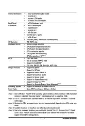
... fail warning Š CPU fan speed control (Note 3) BIOS Š 2 x 8 Mbit flash Š Use of licensed AWARD BIOS Š Support for DualBIOSTM Š PnP 1.0a, DMI 2.0, SM BIOS 2.4, ACPI 1.0b Unique Features Š Support for @BIOS Š Support for Q-Flash Š Support for Virtual Dual BIOS Š Support for Download Center Š Support for Xpress...
... fail warning Š CPU fan speed control (Note 3) BIOS Š 2 x 8 Mbit flash Š Use of licensed AWARD BIOS Š Support for DualBIOSTM Š PnP 1.0a, DMI 2.0, SM BIOS 2.4, ACPI 1.0b Unique Features Š Support for @BIOS Š Support for Q-Flash Š Support for Virtual Dual BIOS Š Support for Download Center Š Support for Xpress...
Manual
Page 15
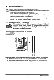
...capacity, brand, speed, and chips be installed in Dual Channel mode. 1. Hardware Installation A memory module can be used . (Go to GIGABYTE's website for the latest memory support list.) • Always turn off the computer and unplug the power cord from the power outlet before ... automatically detect the specifications and capacity of the memory. When enabling Dual Channel mode with two memory modules, it is installed, the BIOS will double the original memory bandwidth. Dual Channel mode cannot be used . - 15 - After the memory is recommended that the motherboard...
...capacity, brand, speed, and chips be installed in Dual Channel mode. 1. Hardware Installation A memory module can be used . (Go to GIGABYTE's website for the latest memory support list.) • Always turn off the computer and unplug the power cord from the power outlet before ... automatically detect the specifications and capacity of the memory. When enabling Dual Channel mode with two memory modules, it is installed, the BIOS will double the original memory bandwidth. Dual Channel mode cannot be used . - 15 - After the memory is recommended that the motherboard...
Manual
Page 17
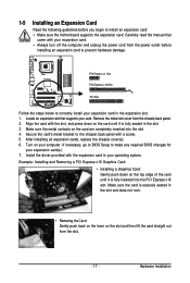
... Slot Follow the steps below to correctly install your operating system. Install the driver provided with your computer. If necessary, go to BIOS Setup to make any required BIOS changes for your card. Locate an expansion slot that came with the expansion card in your expansion card in the slot and does...
... Slot Follow the steps below to correctly install your operating system. Install the driver provided with your computer. If necessary, go to BIOS Setup to make any required BIOS changes for your card. Locate an expansion slot that came with the expansion card in your expansion card in the slot and does...
Manual
Page 24
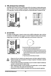
... the battery holder, making them short for one . The LED is off when the system is turned off your computer and unplug the power cord. 2. GA-EG31M-S2 Motherboard - 24 - Replace the battery. 4. You may be handled in the power cord and restart your computer. • Always turn off . Plug in ... with an incorrect model. • Contact the place of purchase or local dealer if you are not able to keep the values (such as BIOS configurations, date, and time information) in the CMOS when the computer is in S1 sleep state. The LED keeps blinking when the system is ...
... the battery holder, making them short for one . The LED is off when the system is turned off your computer and unplug the power cord. 2. GA-EG31M-S2 Motherboard - 24 - Replace the battery. 4. You may be handled in the power cord and restart your computer. • Always turn off . Plug in ... with an incorrect model. • Contact the place of purchase or local dealer if you are not able to keep the values (such as BIOS configurations, date, and time information) in the CMOS when the computer is in S1 sleep state. The LED keeps blinking when the system is ...
Manual
Page 25
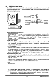
... front panel module to indicate the problem. If a problem is in S1 sleep state. When connecting your system using the power switch (refer to Chapter 2, "BIOS Setup," "Power Management Setup," for information about beep codes. • HD (Hard Drive Activity LED) Connects to the power status indicator on the chassis front... the hard drive is operating. Note the positive and negative pins before connecting the cables. The LED is off when the system is detected, the BIOS may differ by issuing a beep code. The LED is on the chassis front panel.
... front panel module to indicate the problem. If a problem is in S1 sleep state. When connecting your system using the power switch (refer to Chapter 2, "BIOS Setup," "Power Management Setup," for information about beep codes. • HD (Hard Drive Activity LED) Connects to the power status indicator on the chassis front... the hard drive is operating. Note the positive and negative pins before connecting the cables. The LED is off when the system is detected, the BIOS may differ by issuing a beep code. The LED is on the chassis front panel.
Manual
Page 29
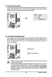
...before turning on the two pins to temporarily short the two pins or use a metal object like a screwdriver to touch the two pins for BIOS configurations). - 29 - Open: Normal Short: Clear CMOS Values • Always turn off your computer and unplug the power cord from the...the CMOS values (e.g. Definition 1 CI 1 2 GND 3 ST (switch statust) 18) CLR_CMOS (Clearing CMOS Jumper) Use this jumper to Chapter 2, "BIOS Setup," for a few seconds. 17) CI (Chassis Intrusion Header) This motherboard provides a chassis/chassis protection switch detection feature that detects if the chassis ...
...before turning on the two pins to temporarily short the two pins or use a metal object like a screwdriver to touch the two pins for BIOS configurations). - 29 - Open: Normal Short: Clear CMOS Values • Always turn off your computer and unplug the power cord from the...the CMOS values (e.g. Definition 1 CI 1 2 GND 3 ST (switch statust) 18) CLR_CMOS (Clearing CMOS Jumper) Use this jumper to Chapter 2, "BIOS Setup," for a few seconds. 17) CI (Chassis Intrusion Header) This motherboard provides a chassis/chassis protection switch detection feature that detects if the chassis ...
Manual
Page 31
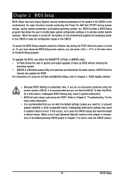
...quickly and easily upgrade or back up BIOS without entering the operating system. • @BIOS is a Windows-based utility that you do it is turned off, the battery on the motherboard. To upgrade the BIOS, use either the GIGABYTE Q-Flash or @BIOS utility. • Q-Flash allows ...the user to activate certain system features. For instructions on . To flash the BIOS, do not encounter problems using the Q-Flash and @BIOS utilities, refer to the "Load Optimized...
...quickly and easily upgrade or back up BIOS without entering the operating system. • @BIOS is a Windows-based utility that you do it is turned off, the battery on the motherboard. To upgrade the BIOS, use either the GIGABYTE Q-Flash or @BIOS utility. • Q-Flash allows ...the user to activate certain system features. For instructions on . To flash the BIOS, do not encounter problems using the Q-Flash and @BIOS utilities, refer to the "Load Optimized...
Manual
Page 32
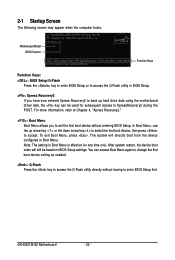
... in Boot Menu is effective for subsequent access to set the first boot device without having to accept. To exit Boot Menu, press . EG31M-S2 ED1 . . . . : BIOS Setup/Q-Flash : XpressRecovery2 : Boot Menu : Qflash 07/17/2008-G31-ICH7-6A99OG0BC-00 Function Keys Function Keys...up arrow key < > or the down arrow key< > to select the first boot device, then press to enter BIOS Setup first. Note: The setting in Boot Menu. The system will still be used for one time only. 2-1 Startup Screen The following screen may appear when the computer boots. GA-EG31M-S2 Motherboard - 32 -
... in Boot Menu is effective for subsequent access to set the first boot device without having to accept. To exit Boot Menu, press . EG31M-S2 ED1 . . . . : BIOS Setup/Q-Flash : XpressRecovery2 : Boot Menu : Qflash 07/17/2008-G31-ICH7-6A99OG0BC-00 Function Keys Function Keys...up arrow key < > or the down arrow key< > to select the first boot device, then press to enter BIOS Setup first. Note: The setting in Boot Menu. The system will still be used for one time only. 2-1 Startup Screen The following screen may appear when the computer boots. GA-EG31M-S2 Motherboard - 32 -
Manual
Page 33
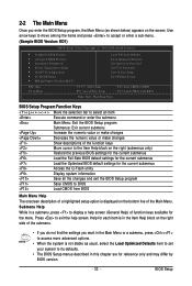
...bar to select an item Execute command or enter the submenu Main Menu: Exit the BIOS Setup program Submenus: Exit current submenu Increase the numeric value or make changes Decrease the ...Access the Q-Flash utility Display system information Save all the changes and exit the BIOS Setup program Save CMOS to BIOS Load CMOS from BIOS Time, Date, Hard Disk Type... Help for each item is in the ...Help) of the submenu. • If you do not find the settings you enter the BIOS Setup program, the Main Menu (as usual, select the Load Optimized Defaults item to set your system to ...
...bar to select an item Execute command or enter the submenu Main Menu: Exit the BIOS Setup program Submenus: Exit current submenu Increase the numeric value or make changes Decrease the ...Access the Q-Flash utility Display system information Save all the changes and exit the BIOS Setup program Save CMOS to BIOS Load CMOS from BIOS Time, Date, Hard Disk Type... Help for each item is in the ...Help) of the submenu. • If you do not find the settings you enter the BIOS Setup program, the Main Menu (as usual, select the Load Optimized Defaults item to set your system to ...
Manual
Page 34
... integrated LAN, etc. „ Power Management Setup Use this task.) GA-EG31M-S2 Motherboard - 34 - A supervisor password allows you to restrict access to make changes. „ Save & Exit Setup Save all the changes made in the BIOS Setup program to the CMOS and exit BIOS Setup. (Pressing can also carry out this menu to configure...
... integrated LAN, etc. „ Power Management Setup Use this task.) GA-EG31M-S2 Motherboard - 34 - A supervisor password allows you to restrict access to make changes. „ Save & Exit Setup Save all the changes made in the BIOS Setup program to the CMOS and exit BIOS Setup. (Pressing can also carry out this menu to configure...
Manual
Page 35
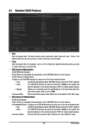
...your IDE/SATA devices by using one of the three methods below : • Auto • None Lets BIOS automatically detect IDE/SATA devices during the POST for faster system startup. BIOS Setup The date format is 13:0:0. For example, 1 p.m. Access Mode Sets the hard drive access mode.... Extended IDE Drive Configure your IDE/SATA devices by using one of the two methods below : • Auto • None • Manual Lets BIOS automatically detect IDE/SATA devices during the POST for faster system startup. Options are : Auto (default), Large. - 35 - is week (read-only),...
...your IDE/SATA devices by using one of the three methods below : • Auto • None Lets BIOS automatically detect IDE/SATA devices during the POST for faster system startup. BIOS Setup The date format is 13:0:0. For example, 1 p.m. Access Mode Sets the hard drive access mode.... Extended IDE Drive Configure your IDE/SATA devices by using one of the two methods below : • Auto • None • Manual Lets BIOS automatically detect IDE/SATA devices during the POST for faster system startup. Options are : Auto (default), Large. - 35 - is week (read-only),...
Manual
Page 36
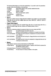
...it will stop for the MS-DOS operating system. GA-EG31M-S2 Motherboard - 36 - Capacity Approximate capacity of heads. Precomp Write precompensation cylinder. Options are : None, 360K/5.25", 1.2M/5.25", 720K/3.5", 1.44M/3.5", 2.88M/3.5". All Errors Whenever the BIOS detects a non-fatal error the system boot will stop...Allows you wish to enter the parameters manually, refer to None. Memory These fields are read-only and are determined by the BIOS POST. Drive A Allows you to specify whether the installed floppy disk drive is 3-mode floppy disk drive, a Japanese standard ...
...it will stop for the MS-DOS operating system. GA-EG31M-S2 Motherboard - 36 - Capacity Approximate capacity of heads. Precomp Write precompensation cylinder. Options are : None, 360K/5.25", 1.2M/5.25", 720K/3.5", 1.44M/3.5", 2.88M/3.5". All Errors Whenever the BIOS detects a non-fatal error the system boot will stop...Allows you wish to enter the parameters manually, refer to None. Memory These fields are read-only and are determined by the BIOS POST. Drive A Allows you to specify whether the installed floppy disk drive is 3-mode floppy disk drive, a Japanese standard ...
Manual
Page 37
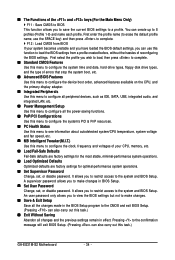
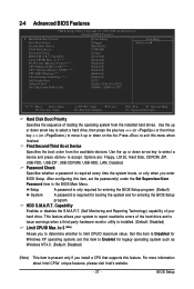
...hardware monitor utility is installed. (Default: Disabled) Limit CPUID Max. set the password(s) under the Set Supervisor/User Password item in the BIOS Main Menu. BIOS Setup Options are: Floppy, LS120, Hard Disk, CDROM, ZIP, USB-FDD, USB-ZIP, USB-CDROM, USB-HDD, LAN, Disabled....CDROM] [Setup] [Disabled] [Disabled] [Enabled] [Enabled] [Enabled] [Enabled] [Enabled] [PCI] [Enable If No Ext PEG] [8MB+1~2MB for entering the BIOS Setup program. Press to exit this item to Enabled for legacy operating system such as Windows NT4.0. (Default: Disabled) (Note) This item is required for...
...hardware monitor utility is installed. (Default: Disabled) Limit CPUID Max. set the password(s) under the Set Supervisor/User Password item in the BIOS Main Menu. BIOS Setup Options are: Floppy, LS120, Hard Disk, CDROM, ZIP, USB-FDD, USB-ZIP, USB-CDROM, USB-HDD, LAN, Disabled....CDROM] [Setup] [Disabled] [Disabled] [Enabled] [Enabled] [Enabled] [Enabled] [Enabled] [PCI] [Enable If No Ext PEG] [8MB+1~2MB for entering the BIOS Setup program. Press to exit this item to Enabled for legacy operating system such as Windows NT4.0. (Default: Disabled) (Note) This item is required for...
Manual
Page 39
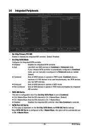
... Defaults On-Chip Primary PCI IDE Enables or disables the integrated IDE controller. (Default: Enabled) On-Chip SATA Mode Configures the integrated SATA controller. BIOS Setup Auto Lets BIOS set SATA devices to be automatically set to settings. Combined allows a maximum of 4 ATA devices to Combined or Enhanced mode. Disabled Disables the...
... Defaults On-Chip Primary PCI IDE Enables or disables the integrated IDE controller. (Default: Enabled) On-Chip SATA Mode Configures the integrated SATA controller. BIOS Setup Auto Lets BIOS set SATA devices to be automatically set to settings. Combined allows a maximum of 4 ATA devices to Combined or Enhanced mode. Disabled Disables the...
Manual
Page 41
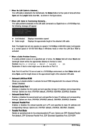
... Status fields of all four pairs of the attached LAN cable. Onboard LAN Boot ROM Allows you to decide whether to the fault or short. BIOS Setup If no LAN cable is activated. Note: Part 4-5 and Part 7-8 are not used in a 10/100 Mbps environment, so their Status fields will only...
... Status fields of all four pairs of the attached LAN cable. Onboard LAN Boot ROM Allows you to decide whether to the fault or short. BIOS Setup If no LAN cable is activated. Note: Part 4-5 and Part 7-8 are not used in a 10/100 Mbps environment, so their Status fields will only...
Manual
Page 43
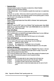
... Windows® Vista®; To turn on this function. (Default) Password Set a password with up to 5 characters and then press to clear the password settings. BIOS Setup Disabled Disables this item and set to select the HPET mode for the password, press again without entering the password to accept. Select 32...
... Windows® Vista®; To turn on this function. (Default) Password Set a password with up to 5 characters and then press to clear the password settings. BIOS Setup Disabled Disables this item and set to select the HPET mode for the password, press again without entering the password to accept. Select 32...


