Manual
Page 4
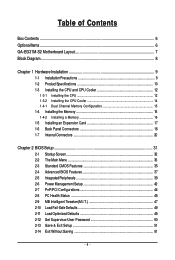
Table of Contents Box Contents ...6 OptionalItems...6 GA-EG31M-S2 Motherboard Layout 7 Block Diagram...8 Chapter 1 Hardware Installation 9 1-1 Installation Precautions 9 1-2 Product Specifications 10 1-3 Installing the CPU and CPU Cooler 12 1-3-1 Installing the CPU 12 1-3-2 Installing the CPU Cooler 14 1-4-1 Dual Channel Memory Configuration 15 1-4 Installing the Memory 15 1-4-2 Installing a Memory 16 1-5 Installing an Expansion Card 17 1-6 Back Panel Connectors...
Table of Contents Box Contents ...6 OptionalItems...6 GA-EG31M-S2 Motherboard Layout 7 Block Diagram...8 Chapter 1 Hardware Installation 9 1-1 Installation Precautions 9 1-2 Product Specifications 10 1-3 Installing the CPU and CPU Cooler 12 1-3-1 Installing the CPU 12 1-3-2 Installing the CPU Cooler 14 1-4-1 Dual Channel Memory Configuration 15 1-4 Installing the Memory 15 1-4-2 Installing a Memory 16 1-5 Installing an Expansion Card 17 1-6 Back Panel Connectors...
Manual
Page 8
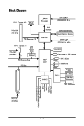
Block Diagram 1 PCI Express x16 D-Sub PCIe CLK (100 MHz) PCI Express x16 1 PCI Express x1 LAN PCIe CLK (100 MHz) x1 RJ45 RTL8111C PCI Express Bus PCI Bus LGA775 Processor Host Interface Intel® G31 CPU CLK+/(333/266/200 MHz) DDR2 800/667 MHz Dual Channel Memory GMCH CLK (333/266/200 MHz) Intel® ICH7 CODEC Dual BIOS ATA-100/66/33 IDE Channel 4 SATA 3Gb/s 8 USB Ports IT8718 Floppy LPT Port COM Port PS/2 KB/Mouse 2 PCI PCI CLK (33 MHz) Surround Speaker Out Center/Subwoofer Speaker Out Side Speaker Out MIC Line-Out Line-In SPDIF In SPDIF Out - 8 -
Block Diagram 1 PCI Express x16 D-Sub PCIe CLK (100 MHz) PCI Express x16 1 PCI Express x1 LAN PCIe CLK (100 MHz) x1 RJ45 RTL8111C PCI Express Bus PCI Bus LGA775 Processor Host Interface Intel® G31 CPU CLK+/(333/266/200 MHz) DDR2 800/667 MHz Dual Channel Memory GMCH CLK (333/266/200 MHz) Intel® ICH7 CODEC Dual BIOS ATA-100/66/33 IDE Channel 4 SATA 3Gb/s 8 USB Ports IT8718 Floppy LPT Port COM Port PS/2 KB/Mouse 2 PCI PCI CLK (33 MHz) Surround Speaker Out Center/Subwoofer Speaker Out Side Speaker Out MIC Line-Out Line-In SPDIF In SPDIF Out - 8 -
Manual
Page 9
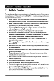
... or connectors. • It is best to the internal connectors on the computer power during the installation process can become damaged as a motherboard, CPU or memory. Hardware Installation Prior to installation, carefully read the user's manual and follow these procedures: • Prior to installation, do not allow screws to come in...
... or connectors. • It is best to the internal connectors on the computer power during the installation process can become damaged as a motherboard, CPU or memory. Hardware Installation Prior to installation, carefully read the user's manual and follow these procedures: • Prior to installation, do not allow screws to come in...
Manual
Page 10
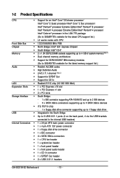
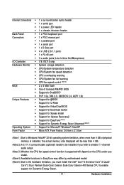
...® G31 Express Chipset Š South Bridge: Intel® ICH7 Memory Š 2 x 1.8V DDR2 DIMM sockets supporting up to 4 GB of system memory(Note 1) Š Dual channel memory architecture Š Support for DDR2 800/667 MHz memory modules (Go to GIGABYTE's website for the latest memory support list.) Audio Š Realtek ALC888 codec Š High Definition... header Š 1 x system fan header Š 1 x front panel header Š 1 x front panel audio header Š 1 x CD In connector Š 1 x S/PDIF Out header Š 2 x USB 2.0/1.1 headers GA-EG31M-S2 Motherboard - 10 -
...® G31 Express Chipset Š South Bridge: Intel® ICH7 Memory Š 2 x 1.8V DDR2 DIMM sockets supporting up to 4 GB of system memory(Note 1) Š Dual channel memory architecture Š Support for DDR2 800/667 MHz memory modules (Go to GIGABYTE's website for the latest memory support list.) Audio Š Realtek ALC888 codec Š High Definition... header Š 1 x system fan header Š 1 x front panel header Š 1 x front panel audio header Š 1 x CD In connector Š 1 x S/PDIF Out header Š 2 x USB 2.0/1.1 headers GA-EG31M-S2 Motherboard - 10 -
Manual
Page 11
... Form Factor; 24.4cm x 21.0cm (Note 1) Due to Windows Vista/XP 32-bit operating system limitation, when more than 4 GB of physical memory is installed, the actual memory size displayed will be less than 4 GB. (Note 2) A 5.1/7.1 surround cable (optional) needs to be installed if you wish to enable 7.1-channel audio output...
... Form Factor; 24.4cm x 21.0cm (Note 1) Due to Windows Vista/XP 32-bit operating system limitation, when more than 4 GB of physical memory is installed, the actual memory size displayed will be less than 4 GB. (Note 2) A 5.1/7.1 surround cable (optional) needs to be installed if you wish to enable 7.1-channel audio output...
Manual
Page 12
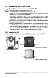
... to your hardware specifications including the CPU, graphics card, memory, hard drive, etc. 1-3-1 Installing the CPU A. Locate the alignment keys on the motherboard CPU socket and the notches on the CPU GA-EG31M-S2 Motherboard - 12 - mended that the motherboard supports the CPU. (Go to GIGABYTE's website for the peripherals. 1-3 Installing the CPU and CPU...
... to your hardware specifications including the CPU, graphics card, memory, hard drive, etc. 1-3-1 Installing the CPU A. Locate the alignment keys on the motherboard CPU socket and the notches on the CPU GA-EG31M-S2 Motherboard - 12 - mended that the motherboard supports the CPU. (Go to GIGABYTE's website for the peripherals. 1-3 Installing the CPU and CPU...
Manual
Page 15
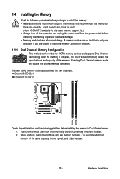
... capacity, brand, speed, and chips be used . (Go to GIGABYTE's website for the latest memory support list.) • Always turn off the computer and unplug the power cord from the power outlet before installing the memory in only one DDR2 memory module is recommended that memory of the same capacity, brand, speed, and chips be...
... capacity, brand, speed, and chips be used . (Go to GIGABYTE's website for the latest memory support list.) • Always turn off the computer and unplug the power cord from the power outlet before installing the memory in only one DDR2 memory module is recommended that memory of the same capacity, brand, speed, and chips be...
Manual
Page 16
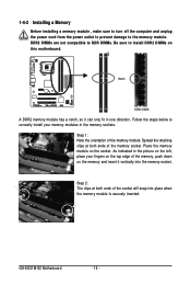
.... Notch DDR2 DIMM A DDR2 memory module has a notch, so it vertically into place when the memory module is securely inserted. Step 2: The clips at both ends of the memory, push down on the memory and insert it can only fit in the memory sockets. GA-EG31M-S2 Motherboard - 16 - Follow the... steps below to correctly install your fingers on the top edge of the socket will snap into the memory socket. Step 1: Note the...
.... Notch DDR2 DIMM A DDR2 memory module has a notch, so it vertically into place when the memory module is securely inserted. Step 2: The clips at both ends of the memory, push down on the memory and insert it can only fit in the memory sockets. GA-EG31M-S2 Motherboard - 16 - Follow the... steps below to correctly install your fingers on the top edge of the socket will snap into the memory socket. Step 1: Note the...
Manual
Page 34
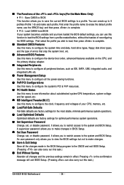
...configure all peripheral devices, such as IDE, SATA, USB, integrated audio, and integrated LAN, etc. „ Power Management Setup Use this task.) GA-EG31M-S2 Motherboard - 34 - An user password only allows you to view the BIOS settings but not to make changes in effect. It allows you to restrict...wish to load, then press to complete. „ Standard CMOS Features Use this function to load the BIOS settings from BIOS If your CPU, memory, etc. „ Load Fail-Safe Defaults Fail-Safe defaults are factory settings for the most stable, minimal-performance system operations. „ Load ...
...configure all peripheral devices, such as IDE, SATA, USB, integrated audio, and integrated LAN, etc. „ Power Management Setup Use this task.) GA-EG31M-S2 Motherboard - 34 - An user password only allows you to view the BIOS settings but not to make changes in effect. It allows you to restrict...wish to load, then press to complete. „ Standard CMOS Features Use this function to load the BIOS settings from BIOS If your CPU, memory, etc. „ Load Fail-Safe Defaults Fail-Safe defaults are factory settings for the most stable, minimal-performance system operations. „ Load ...
Manual
Page 35
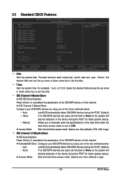
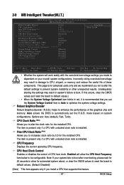
... ` IDE Channel 3 Master ` IDE Channel 3 Slave [None] [None] [None] [None] [None] [None] Drive A Floppy 3 Mode Support [1.44M, 3.5"] [Disabled] Halt On [All, But Keyboard] Base Memory Extended Memory Total Memory 640K 510M 512M KLJI: Move Enter: Select F5: Previous Values +/-/PU/PD: Value F10: Save F6: Fail-Safe Defaults ESC: Exit F1: General Help...
... ` IDE Channel 3 Master ` IDE Channel 3 Slave [None] [None] [None] [None] [None] [None] Drive A Floppy 3 Mode Support [1.44M, 3.5"] [Disabled] Halt On [All, But Keyboard] Base Memory Extended Memory Total Memory 640K 510M 512M KLJI: Move Enter: Select F5: Previous Values +/-/PU/PD: Value F10: Save F6: Fail-Safe Defaults ESC: Exit F1: General Help...
Manual
Page 36
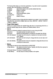
... keyboard or a floppy disk drive error but stop for all other errors. Typically, 640 KB will stop for the MS-DOS operating system. GA-EG31M-S2 Motherboard - 36 - Sector Number of heads. Halt On Allows you to determine whether the system will stop for all other errors. (Default...3 Mode Support Allows you to the information on the system. If you wish to enter the parameters manually, refer to selects the type of memory installed on the hard drive. Options are : None, 360K/5.25", 1.2M/5.25", 720K/3.5", 1.44M/3.5", 2.88M/3.5". All Errors Whenever the BIOS ...
... keyboard or a floppy disk drive error but stop for all other errors. Typically, 640 KB will stop for the MS-DOS operating system. GA-EG31M-S2 Motherboard - 36 - Sector Number of heads. Halt On Allows you to determine whether the system will stop for all other errors. (Default...3 Mode Support Allows you to the information on the system. If you wish to enter the parameters manually, refer to selects the type of memory installed on the hard drive. Options are : None, 360K/5.25", 1.2M/5.25", 720K/3.5", 1.44M/3.5", 2.88M/3.5". All Errors Whenever the BIOS ...
Manual
Page 37
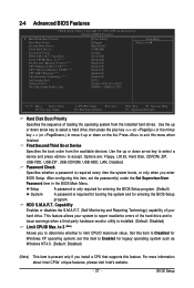
... the BIOS Setup program. to limit CPUID maximum value. BIOS Setup Press to accept. to 3 (Note) Allows you to determine whether to 3 (Note) No-Execute Memory Protect (Note) CPU Enhanced Halt (C1E) (Note) CPU Thermal Monitor 2(TM2) (Note) CPU EIST Function (Note) Virtualization Technology (Note) Init Display First Onboard VGA On...
... the BIOS Setup program. to limit CPUID maximum value. BIOS Setup Press to accept. to 3 (Note) Allows you to determine whether to 3 (Note) No-Execute Memory Protect (Note) CPU Enhanced Halt (C1E) (Note) CPU Thermal Monitor 2(TM2) (Note) CPU EIST Function (Note) Virtualization Technology (Note) Init Display First Onboard VGA On...
Manual
Page 38
...to set up a dual view configuration, set this item to Always Enable. Onboard VGA Enables or disables the onboard VGA function. GA-EG31M-S2 Motherboard - 38 - When enabled, the CPU core frequency and voltage will be reduced during system halt state to run multiple ...loading, Intel® EIST technology can function as multiple virtual systems. (Default: Enabled) Init Display First Specifies the first initiation of system memory allocated solely for GTT. (Note) This item is overheated. (Default: Enabled) CPU EIST Function (Note) Enables or disables Enhanced Intel ...
...to set up a dual view configuration, set this item to Always Enable. Onboard VGA Enables or disables the onboard VGA function. GA-EG31M-S2 Motherboard - 38 - When enabled, the CPU core frequency and voltage will be reduced during system halt state to run multiple ...loading, Intel® EIST technology can function as multiple virtual systems. (Default: Enabled) Init Display First Specifies the first initiation of system memory allocated solely for GTT. (Note) This item is overheated. (Default: Enabled) CPU EIST Function (Note) Enables or disables Enhanced Intel ...
Manual
Page 43
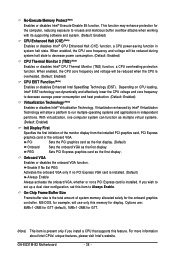
... a password with 1~5 characters to turn on the system. Press on this function. (Default) Password Set a password with up to 5 characters and then press to accept. Memory The system returns to turn on the system. Note: When using this item. HPET Support (Note) Enables or disables High Precision Event Timer (HPET) for...
... a password with 1~5 characters to turn on the system. Press on this function. (Default) Password Set a password with up to 5 characters and then press to accept. Memory The system returns to turn on the system. Note: When using this item. HPET Support (Note) Enables or disables High Precision Event Timer (HPET) for...
Manual
Page 47
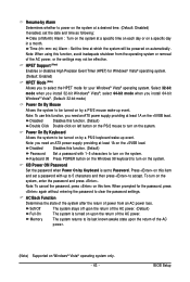
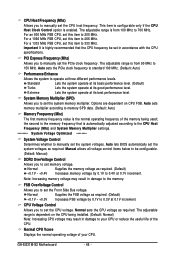
Auto allows the BIOS to enhance the performance of the graphics chip and memory. The item is present only if a CPU with unlocked clock ratio is installed. The item is present only if a CPU with unlocked clock ratio ...Ratio (Note) Fine CPU Clock Ratio (Note) CPU Frequency CPU Host Clock Control x CPU Host Frequency (Mhz) PCI Express Frequency (Mhz) Performance Enhance System Memory Multiplier (SPD) Memory Frequency (Mhz) 800 ******** System Voltage Optimized System Voltage Control DDR2 OverVoltage Control FSB OverVoltage Control CPU Voltage Control Normal CPU Vcore [Auto] [7X] [+0.5] 2....
Auto allows the BIOS to enhance the performance of the graphics chip and memory. The item is present only if a CPU with unlocked clock ratio is installed. The item is present only if a CPU with unlocked clock ratio ...Ratio (Note) Fine CPU Clock Ratio (Note) CPU Frequency CPU Host Clock Control x CPU Host Frequency (Mhz) PCI Express Frequency (Mhz) Performance Enhance System Memory Multiplier (SPD) Memory Frequency (Mhz) 800 ******** System Voltage Optimized System Voltage Control DDR2 OverVoltage Control FSB OverVoltage Control CPU Voltage Control Normal CPU Vcore [Auto] [7X] [+0.5] 2....
Manual
Page 48
.... (Default) Turbo Lets the system operate at its good performance level. Normal Supplies the memory voltage as required. System Memory Multiplier (SPD) Allows you to set the CPU voltage. CPU Voltage Control Allows you to set the system memory multiplier. GA-EG31M-S2 Motherboard - 48 - For an 800 MHz FSB CPU, set this item to 333...
.... (Default) Turbo Lets the system operate at its good performance level. Normal Supplies the memory voltage as required. System Memory Multiplier (SPD) Allows you to set the CPU voltage. CPU Voltage Control Allows you to set the system memory multiplier. GA-EG31M-S2 Motherboard - 48 - For an 800 MHz FSB CPU, set this item to 333...
Manual
Page 57
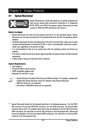
... your system soon after the operating system and drivers are not supported. System Requirements: • Intel® platform • At least 64 MB of system memory • VESA compatible graphics card • Windows® XP with Xpress Recovery cannot be restored using Xpress Recovery2. • USB hard drives are not supported...
... your system soon after the operating system and drivers are not supported. System Requirements: • Intel® platform • At least 64 MB of system memory • VESA compatible graphics card • Windows® XP with Xpress Recovery cannot be restored using Xpress Recovery2. • USB hard drives are not supported...
Manual
Page 66
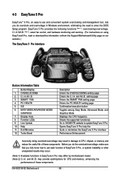
... Toggles among Easy Mode, Advanced Mode, and Graphics Mode Displays the CPU frequency Shows the supported function(s) Go to GIGABYTE website to update EasyTune 5 Pro Opens EasyTune 5 Pro help file Quits or minimizes the EasyTune 5 Pro interface Performance...5 Pro may differ by motherboard model. (Note 2) C.I .B. PC HEALTH 5. Live Update 10. GA-EG31M-S2 Motherboard - 66 - EASY MODE/ADVANCED MODE/ GRAPHICS 7. OVERCLOCKING 2. Display Area 8. may provide optimizations for CPU and memory, enhancing the performance of these components. GO 6. and M.I .A. EasyTune 5 Pro provides the following ...
... Toggles among Easy Mode, Advanced Mode, and Graphics Mode Displays the CPU frequency Shows the supported function(s) Go to GIGABYTE website to update EasyTune 5 Pro Opens EasyTune 5 Pro help file Quits or minimizes the EasyTune 5 Pro interface Performance...5 Pro may differ by motherboard model. (Note 2) C.I .B. PC HEALTH 5. Live Update 10. GA-EG31M-S2 Motherboard - 66 - EASY MODE/ADVANCED MODE/ GRAPHICS 7. OVERCLOCKING 2. Display Area 8. may provide optimizations for CPU and memory, enhancing the performance of these components. GO 6. and M.I .A. EasyTune 5 Pro provides the following ...
Manual
Page 77
... jumper, refer to the CMOS, which will clear the CMOS values after the computer shuts down and that's why the light is still on GIGABYTE's website. Select "Load Fail-Safe Defaults" (or "Load Optimized Defaults") to show the advanced options. Q:Why do I still get a ... code descriptions may help you identify possible computer problems. (For reference only.) 1 short: System boots successfully 2 short: CMOS setting error 1 long, 1 short: Memory or motherboard error 1 long, 2 short: Monitor or graphics card error 1 long, 3 short: Keyboard error 1 long, 9 short: BIOS ROM error Continuous long...
... jumper, refer to the CMOS, which will clear the CMOS values after the computer shuts down and that's why the light is still on GIGABYTE's website. Select "Load Fail-Safe Defaults" (or "Load Optimized Defaults") to show the advanced options. Q:Why do I still get a ... code descriptions may help you identify possible computer problems. (For reference only.) 1 short: System boots successfully 2 short: CMOS setting error 1 long, 1 short: Memory or motherboard error 1 long, 2 short: Monitor or graphics card error 1 long, 3 short: Keyboard error 1 long, 9 short: BIOS ROM error Continuous long...
Manual
Page 78
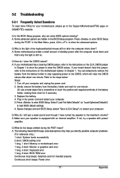
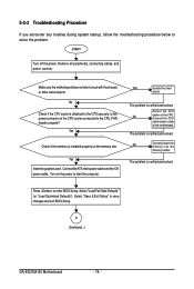
... troubles during system startup, follow the troubleshooting procedure below to save changes and exit BIOS Setup. No Correctly insert the memory into the memory socket. Select "Load Fail-Safe Defaults" (or "Load Optimized Defaults"). Remove all peripherals, connecting cables, and power cord...-circuit with the chassis or other metal objects. Yes Check if the memory is verified and solved. Turn on the power to start the computer. Yes Isolate the short circuit. The problem is installed properly on the CPU. A (Continued...) GA-EG31M-S2 Motherboard - 78 -
... troubles during system startup, follow the troubleshooting procedure below to save changes and exit BIOS Setup. No Correctly insert the memory into the memory socket. Select "Load Fail-Safe Defaults" (or "Load Optimized Defaults"). Remove all peripherals, connecting cables, and power cord...-circuit with the chassis or other metal objects. Yes Check if the memory is verified and solved. Turn on the power to start the computer. Yes Isolate the short circuit. The problem is installed properly on the CPU. A (Continued...) GA-EG31M-S2 Motherboard - 78 -


