Manual
Page 1
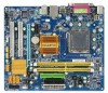
GA-EG31M-S2 LGA775 socket motherboard for Intel® CoreTM processor family/ Intel® Pentium® processor family/Intel® Celeron® processor family User's Manual Rev. 2001 12ME-EG31MS2-2001R
GA-EG31M-S2 LGA775 socket motherboard for Intel® CoreTM processor family/ Intel® Pentium® processor family/Intel® Celeron® processor family User's Manual Rev. 2001 12ME-EG31MS2-2001R
Manual
Page 3
... Changes to use of this product, GIGABYTE provides the following types of this manual may be reproduced, copied, translated, transmitted, or published in this manual may be made by any form or by GIGABYTE without GIGABYTE's prior written permission. Documentation Classifications In... order to assist in the use GIGABYTE's unique features, read the User's Manual. „ For instructions on how to the specifications and features in this manual are legally registered to GIGABYTE UNITED INC. Example: GIGABYTE UNITED INC. Copyright © 2008 GIGA...
... Changes to use of this product, GIGABYTE provides the following types of this manual may be reproduced, copied, translated, transmitted, or published in this manual may be made by any form or by GIGABYTE without GIGABYTE's prior written permission. Documentation Classifications In... order to assist in the use GIGABYTE's unique features, read the User's Manual. „ For instructions on how to the specifications and features in this manual are legally registered to GIGABYTE UNITED INC. Example: GIGABYTE UNITED INC. Copyright © 2008 GIGA...
Manual
Page 5
Chapter 3 Drivers Installation 53 3-1 Installing Chipset Drivers 53 3-2 Application Software 54 3-3 Technical Manuals 54 3-4 Contact ...55 3-5 System ...55 3-6 Download Center 56 Chapter 4 Unique Features 57 4-1 Xpress Recovery2 57 4-2 BIOS Update Utilities 62 4-2-1 Updating the BIOS with the Q-Flash ...
Chapter 3 Drivers Installation 53 3-1 Installing Chipset Drivers 53 3-2 Application Software 54 3-3 Technical Manuals 54 3-4 Contact ...55 3-5 System ...55 3-6 Download Center 56 Chapter 4 Unique Features 57 4-1 Xpress Recovery2 57 4-2 BIOS Update Utilities 62 4-2-1 Updating the BIOS with the Q-Flash ...
Manual
Page 6
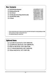
... (Part No. 12CR1-1SPOUT-02R) 5.1/7.1 Surround cable (Part No. 12CF1-1AU004-01R) COM port cable (Part No. 12CF1-1CM001-32R) - 6 - Box Contents GA-EG31M-S2 motherboard Motherboard driver disk User's Manual One IDE cable and one floppy disk drive cable Two SATA 3Gb/s cables I/O Shield • The box contents above are subject to change...
... (Part No. 12CR1-1SPOUT-02R) 5.1/7.1 Surround cable (Part No. 12CF1-1AU004-01R) COM port cable (Part No. 12CF1-1CM001-32R) - 6 - Box Contents GA-EG31M-S2 motherboard Motherboard driver disk User's Manual One IDE cable and one floppy disk drive cable Two SATA 3Gb/s cables I/O Shield • The box contents above are subject to change...
Manual
Page 9
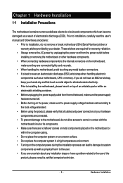
Prior to installation, carefully read the user's manual and follow these procedures: • Prior to wear an electrostatic discharge (ESD) wrist strap when handling electronic components such as a motherboard, CPU or memory. Chapter 1 ...
Prior to installation, carefully read the user's manual and follow these procedures: • Prior to wear an electrostatic discharge (ESD) wrist strap when handling electronic components such as a motherboard, CPU or memory. Chapter 1 ...
Manual
Page 14
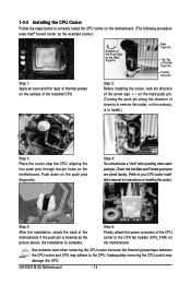
Step 4: You should hear a "click" when pushing down on the push pins diagonally. GA-EG31M-S2 Motherboard - 14 - If the push pin is inserted as the example cooler.) Step 1: Apply an even and thin layer of thermal grease on the surface ... direction of the arrow sign on the motherboard. Check that the Male and Female push pins are joined closely. (Refer to your CPU cooler installation manual for instructions on installing the cooler.) Step 5: After the installation, check the back of arrow is to remove the cooler, on the contrary, is to...
Step 4: You should hear a "click" when pushing down on the push pins diagonally. GA-EG31M-S2 Motherboard - 14 - If the push pin is inserted as the example cooler.) Step 1: Apply an even and thin layer of thermal grease on the surface ... direction of the arrow sign on the motherboard. Check that the Male and Female push pins are joined closely. (Refer to your CPU cooler installation manual for instructions on installing the cooler.) Step 5: After the installation, check the back of arrow is to remove the cooler, on the contrary, is to...
Manual
Page 17
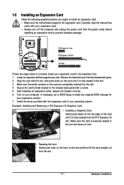
... expansion card: • Make sure the motherboard supports the expansion card. If necessary, go to BIOS Setup to correctly install your card. Carefully read the manual that supports your expansion card in the expansion slot. 1. Locate an expansion slot that came with the slot, and press down on your expansion card...
... expansion card: • Make sure the motherboard supports the expansion card. If necessary, go to BIOS Setup to correctly install your card. Carefully read the manual that supports your expansion card in the expansion slot. 1. Locate an expansion slot that came with the slot, and press down on your expansion card...
Manual
Page 29
... do so may cause damage to the motherboard. • After system restart, go to BIOS Setup to load factory defaults (select Load Optimized Defaults) or manually configure the BIOS settings (refer to Chapter 2, "BIOS Setup," for a few seconds. Definition 1 CI 1 2 GND 3 ST (switch statust) 18) CLR_CMOS (Clearing CMOS Jumper) Use this...
... do so may cause damage to the motherboard. • After system restart, go to BIOS Setup to load factory defaults (select Load Optimized Defaults) or manually configure the BIOS settings (refer to Chapter 2, "BIOS Setup," for a few seconds. Definition 1 CI 1 2 GND 3 ST (switch statust) 18) CLR_CMOS (Clearing CMOS Jumper) Use this...
Manual
Page 35
... devices during the POST. (Default) If no IDE/SATA devices are used , set this channel. Allows you to manually enter the specifications of the two methods below : • Auto • None • Manual Lets BIOS automatically detect IDE/SATA devices during the POST. (Default) If no IDE/SATA devices are used , set...
... devices during the POST. (Default) If no IDE/SATA devices are used , set this channel. Allows you to manually enter the specifications of the two methods below : • Auto • None • Manual Lets BIOS automatically detect IDE/SATA devices during the POST. (Default) If no IDE/SATA devices are used , set...
Manual
Page 36
... errors. All, But Disk/Key The system boot will stop . Halt On Allows you wish to enter the parameters manually, refer to selects the type of floppy disk drive installed in your hard drive specifications. If you to specify whether.../5.25", 1.2M/5.25", 720K/3.5", 1.44M/3.5", 2.88M/3.5". Base Memory Also called conventional memory. Total Memory The total amount of extended memory. GA-EG31M-S2 Motherboard - 36 - Precomp Write precompensation cylinder. Landing Zone Landing zone. The following fields display your system. Floppy 3 Mode Support Allows you...
... errors. All, But Disk/Key The system boot will stop . Halt On Allows you wish to enter the parameters manually, refer to selects the type of floppy disk drive installed in your hard drive specifications. If you to specify whether.../5.25", 1.2M/5.25", 720K/3.5", 1.44M/3.5", 2.88M/3.5". Base Memory Also called conventional memory. Total Memory The total amount of extended memory. GA-EG31M-S2 Motherboard - 36 - Precomp Write precompensation cylinder. Landing Zone Landing zone. The following fields display your system. Floppy 3 Mode Support Allows you...
Manual
Page 39
... option will be used simultaneously: two PATA devices plus two SATA devices. When PATA IDE Set to is automatically configured to Combined mode, you can manually re-configure it to Enhanced mode as needed. (Default) Combined Sets all SATA devices to Ch. 1 Master/Slave. PATA IDE Set to This item is...
... option will be used simultaneously: two PATA devices plus two SATA devices. When PATA IDE Set to is automatically configured to Combined mode, you can manually re-configure it to Enhanced mode as needed. (Default) Combined Sets all SATA devices to Ch. 1 Master/Slave. PATA IDE Set to This item is...
Manual
Page 47
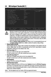
... System Voltage Control DDR2 OverVoltage Control FSB OverVoltage Control CPU Voltage Control Normal CPU Vcore [Auto] [7X] [+0.5] 2.50GHz(333x7.5) [Disabled] 333 [Auto] [Standard] [Auto] 800 ******** [Manual] [Normal] [Normal] [Normal] 1.22500V Item Help Menu Level` KLJI: Move Enter: Select F5: Previous Values +/-/PU/PD: Value F10: Save F6: Fail-Safe Defaults ESC...
... System Voltage Control DDR2 OverVoltage Control FSB OverVoltage Control CPU Voltage Control Normal CPU Vcore [Auto] [7X] [+0.5] 2.50GHz(333x7.5) [Disabled] 333 [Auto] [Standard] [Auto] 800 ******** [Manual] [Normal] [Normal] [Normal] 1.22500V Item Help Menu Level` KLJI: Move Enter: Select F5: Previous Values +/-/PU/PD: Value F10: Save F6: Fail-Safe Defaults ESC...
Manual
Page 48
...Default: Auto) Performance Enhance Allows the system to set memory voltage. Auto sets memory multiplier according to set the CPU voltage. Manual allows all voltage control items below to be set the PCIe clock frequency. Normal sets the CPU voltage as required. PCI Express...with the CPU specifications. The adjustable range is the normal operating frequency of the CPU. Options are dependent on the CPU being used; GA-EG31M-S2 Motherboard - 48 - CPU Host Frequency (Mhz) Allows you to 700 MHz. Normal Supplies the memory voltage as required. (Default) +0....
...Default: Auto) Performance Enhance Allows the system to set memory voltage. Auto sets memory multiplier according to set the CPU voltage. Manual allows all voltage control items below to be set the PCIe clock frequency. Normal sets the CPU voltage as required. PCI Express...with the CPU specifications. The adjustable range is the normal operating frequency of the CPU. Options are dependent on the CPU being used; GA-EG31M-S2 Motherboard - 48 - CPU Host Frequency (Mhz) Allows you to 700 MHz. Normal Supplies the memory voltage as required. (Default) +0....
Manual
Page 53
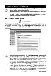
... instructions to install. • Please ignore the popup dialog box(es) (e.g. The driver Autorun screen is installing the drivers. Or click Install Single Items to manually select the drivers you wish to restart your system and then list all the recommended drivers. You can install other drivers. • After the drivers...
... instructions to install. • Please ignore the popup dialog box(es) (e.g. The driver Autorun screen is installing the drivers. Or click Install Single Items to manually select the drivers you wish to restart your system and then list all the recommended drivers. You can install other drivers. • After the drivers...
Manual
Page 54
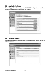
3-2 Application Software This page displays all the utilities and applications that GIGABYTE develops and some free software. GA-EG31M-S2 Motherboard - 54 - You can click the Install button on the right of an item to install it. 3-3 Technical Manuals This page provides GIGABYTE's application guides, content descriptions for this driver disk, and the motherboard manuals.
3-2 Application Software This page displays all the utilities and applications that GIGABYTE develops and some free software. GA-EG31M-S2 Motherboard - 54 - You can click the Install button on the right of an item to install it. 3-3 Technical Manuals This page provides GIGABYTE's application guides, content descriptions for this driver disk, and the motherboard manuals.
Manual
Page 55
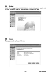
Or read the last page of this page to link to check the contact information for GIGABYTE Taiwan headquarter or worldwide branch offices. 3-5 System This page provides the basic system information. - 55 - Drivers Installation 3-4 Contact Click the URL on this manual to the GIGABYTE Web site.
Or read the last page of this page to link to check the contact information for GIGABYTE Taiwan headquarter or worldwide branch offices. 3-5 System This page provides the basic system information. - 55 - Drivers Installation 3-4 Contact Click the URL on this manual to the GIGABYTE Web site.
Manual
Page 65
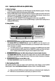
... connection is not present on the @BIOS server site, please manually download the BIOS update file from an inadequate BIOS flashing. GIGABYTE product warranty does not cover any BIOS damage or system failure resulting from GIGABYTE's website and follow the instruc- Make sure that matches your... Update Function: Click Update BIOS from File, then select the location where you save the current BIOS file. Do not use the G.O.M. (GIGABYTE Online Management) function when using @BIOS. 4. After Updating the BIOS: After updating the BIOS, restart your system. As the system boots,...
... connection is not present on the @BIOS server site, please manually download the BIOS update file from an inadequate BIOS flashing. GIGABYTE product warranty does not cover any BIOS damage or system failure resulting from GIGABYTE's website and follow the instruc- Make sure that matches your... Update Function: Click Update BIOS from File, then select the location where you save the current BIOS file. Do not use the G.O.M. (GIGABYTE Online Management) function when using @BIOS. 4. After Updating the BIOS: After updating the BIOS, restart your system. As the system boots,...
Manual
Page 70
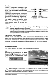
...Out) The integrated HD (High Definition) audio provides Mic In jack retasking capability that allows the user to the three onboard audio jacks. GA-EG31M-S2 Motherboard - 70 - Audio Jacks: The 5.1/7.1 surround cable adds additional three audio jacks to change the function for each jack through the ...audio driver. High Definition Audio (HD Audio) HD Audio includes multiple high quality digital-to the Mic in jack and manually configure the jack for Windows. Audio Jacks on the 5.1/7.1 Surround Cable • To install a microphone, connect your system tray. ...
...Out) The integrated HD (High Definition) audio provides Mic In jack retasking capability that allows the user to the three onboard audio jacks. GA-EG31M-S2 Motherboard - 70 - Audio Jacks: The 5.1/7.1 surround cable adds additional three audio jacks to change the function for each jack through the ...audio driver. High Definition Audio (HD Audio) HD Audio includes multiple high quality digital-to the Mic in jack and manually configure the jack for Windows. Audio Jacks on the 5.1/7.1 Surround Cable • To install a microphone, connect your system tray. ...
Manual
Page 80
...Directive Statement GIGABYTE products have been carefully selected to the waste collection centers for errors or omissions in a manner that do not use of electric and electronic devices and their components. Restriction of the treatment, collection, recycling and disposal procedure. GA-EG31M-S2 Motherboard ... that the information contained herein was accurate in your product's user's manual and we at the time of properly. Waste Electrical & Electronic Equipment (WEEE) Directive Statement GIGABYTE will help you may contact us at the Customer Care number listed ...
...Directive Statement GIGABYTE products have been carefully selected to the waste collection centers for errors or omissions in a manner that do not use of electric and electronic devices and their components. Restriction of the treatment, collection, recycling and disposal procedure. GA-EG31M-S2 Motherboard ... that the information contained herein was accurate in your product's user's manual and we at the time of properly. Waste Electrical & Electronic Equipment (WEEE) Directive Statement GIGABYTE will help you may contact us at the Customer Care number listed ...


