Manual
Page 1
GA-EG31M-S2 LGA775 socket motherboard for Intel® CoreTM processor family/ Intel® Pentium® processor family/Intel® Celeron® processor family User's Manual Rev. 2001 12ME-EG31MS2-2001R
GA-EG31M-S2 LGA775 socket motherboard for Intel® CoreTM processor family/ Intel® Pentium® processor family/Intel® Celeron® processor family User's Manual Rev. 2001 12ME-EG31MS2-2001R
Manual
Page 2
Motherboard GA-EG31M-S2 Jul. 30, 2008 Motherboard GA-EG31M-S2 Jul. 30, 2008
Motherboard GA-EG31M-S2 Jul. 30, 2008 Motherboard GA-EG31M-S2 Jul. 30, 2008
Manual
Page 3
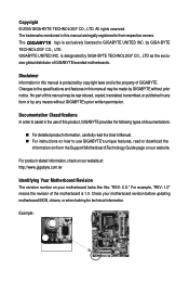
..., drivers, or when looking for technical information. For example, "REV: 1.0" means the revision of GIGABYTE branded motherboards. is the property of GIGABYTE. Changes to GIGABYTE UNITED INC. sive global distributor of the motherboard is exclusively licensed to the specifications and features in this manual is protected by copyright laws and is designated by GIGA-BYTE...
..., drivers, or when looking for technical information. For example, "REV: 1.0" means the revision of GIGABYTE branded motherboards. is the property of GIGABYTE. Changes to GIGABYTE UNITED INC. sive global distributor of the motherboard is exclusively licensed to the specifications and features in this manual is protected by copyright laws and is designated by GIGA-BYTE...
Manual
Page 4
Table of Contents Box Contents ...6 OptionalItems...6 GA-EG31M-S2 Motherboard Layout 7 Block Diagram...8 Chapter 1 Hardware Installation 9 1-1 Installation Precautions 9 1-2 Product Specifications 10 1-3 Installing the CPU and CPU Cooler 12 1-3-1 Installing the CPU 12 1-3-2 Installing the CPU ...
Table of Contents Box Contents ...6 OptionalItems...6 GA-EG31M-S2 Motherboard Layout 7 Block Diagram...8 Chapter 1 Hardware Installation 9 1-1 Installation Precautions 9 1-2 Product Specifications 10 1-3 Installing the CPU and CPU Cooler 12 1-3-1 Installing the CPU 12 1-3-2 Installing the CPU ...
Manual
Page 6
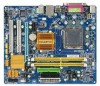
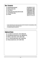
... No. 12CR1-1SPOUT-02R) 5.1/7.1 Surround cable (Part No. 12CF1-1AU004-01R) COM port cable (Part No. 12CF1-1CM001-32R) - 6 - Box Contents GA-EG31M-S2 motherboard Motherboard driver disk User's Manual One IDE cable and one floppy disk drive cable Two SATA 3Gb/s cables I/O Shield • The box contents above are subject... to change without notice. • The motherboard image is for reference only and the actual items shall depend on product package you obtain. The box contents are for reference only.
... No. 12CR1-1SPOUT-02R) 5.1/7.1 Surround cable (Part No. 12CF1-1AU004-01R) COM port cable (Part No. 12CF1-1CM001-32R) - 6 - Box Contents GA-EG31M-S2 motherboard Motherboard driver disk User's Manual One IDE cable and one floppy disk drive cable Two SATA 3Gb/s cables I/O Shield • The box contents above are subject... to change without notice. • The motherboard image is for reference only and the actual items shall depend on product package you obtain. The box contents are for reference only.
Manual
Page 7
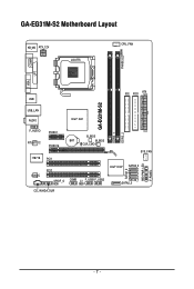
GA-EG31M-S2 Motherboard Layout KB_MS ATX_12V LGA775 CPU_FAN PHASE LED COMA LPT VGA IDE FDD ATX USB GA-EG31M-S2 DDR2_1 DDR2_2 USB_LAN AUDIO Intel® G31 F_AUDIO RTL8111C IT8718 CODEC PCIEX1 PCIEX16 B_BIOS BAT M_BIOS CLR_CMOS PCI1 PCI2 SPDIF_O COMB CI F_USB1F_USB2 SYS_FAN Intel® ICH7 SATA2_3 SATA2_1 SATA2_0 CD_IN HDA_SUR SATA2_2 PWR_LED F_PANEL - 7 -
GA-EG31M-S2 Motherboard Layout KB_MS ATX_12V LGA775 CPU_FAN PHASE LED COMA LPT VGA IDE FDD ATX USB GA-EG31M-S2 DDR2_1 DDR2_2 USB_LAN AUDIO Intel® G31 F_AUDIO RTL8111C IT8718 CODEC PCIEX1 PCIEX16 B_BIOS BAT M_BIOS CLR_CMOS PCI1 PCI2 SPDIF_O COMB CI F_USB1F_USB2 SYS_FAN Intel® ICH7 SATA2_3 SATA2_1 SATA2_0 CD_IN HDA_SUR SATA2_2 PWR_LED F_PANEL - 7 -
Manual
Page 9
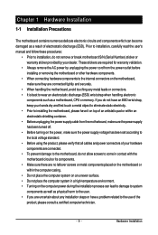
... please verify that all cables and power connectors of your dealer. If you are connected tightly and securely. • When handling the motherboard, avoid touching any installation steps or have a problem related to the use of the product, please consult a certified computer technician. -... 9 - Chapter 1 Hardware Installation 1-1 Installation Precautions The motherboard contains numerous delicate electronic circuits and components which can lead to damage to system components as well as physical harm to the user....
... please verify that all cables and power connectors of your dealer. If you are connected tightly and securely. • When handling the motherboard, avoid touching any installation steps or have a problem related to the use of the product, please consult a certified computer technician. -... 9 - Chapter 1 Hardware Installation 1-1 Installation Precautions The motherboard contains numerous delicate electronic circuits and components which can lead to damage to system components as well as physical harm to the user....
Manual
Page 10
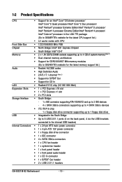
...Intel® Pentium® 4 processor/ Intel® Celeron® processor in the LGA 775 package (Go to GIGABYTE's website for the latest CPU support list.) Š L2 cache varies with CPU Front Side Bus Š ...(Note 1) Š Dual channel memory architecture Š Support for DDR2 800/667 MHz memory modules (Go to GIGABYTE's website for the latest memory support list.) Audio Š Realtek ALC888 codec Š High Definition Audio Š...panel audio header Š 1 x CD In connector Š 1 x S/PDIF Out header Š 2 x USB 2.0/1.1 headers GA-EG31M-S2 Motherboard - 10 -
...Intel® Pentium® 4 processor/ Intel® Celeron® processor in the LGA 775 package (Go to GIGABYTE's website for the latest CPU support list.) Š L2 cache varies with CPU Front Side Bus Š ...(Note 1) Š Dual channel memory architecture Š Support for DDR2 800/667 MHz memory modules (Go to GIGABYTE's website for the latest memory support list.) Audio Š Realtek ALC888 codec Š High Definition Audio Š...panel audio header Š 1 x CD In connector Š 1 x S/PDIF Out header Š 2 x USB 2.0/1.1 headers GA-EG31M-S2 Motherboard - 10 -
Manual
Page 11
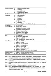
... 3) Whether the CPU fan speed control function is supported will depend on the CPU cooler you install. (Note 4) Available functions in EasyTune may differ by motherboard model. (Note 5) Due to the hardware limitation, you must install the Intel® CoreTM 2 Extreme/ CoreTM 2 Quad/ CoreTM 2 Duo/ Pentium Dual-Core/ Celeron Dual-Core...
... 3) Whether the CPU fan speed control function is supported will depend on the CPU cooler you install. (Note 4) Available functions in EasyTune may differ by motherboard model. (Note 5) Due to the hardware limitation, you must install the Intel® CoreTM 2 Extreme/ CoreTM 2 Quad/ CoreTM 2 Duo/ Pentium Dual-Core/ Celeron Dual-Core...
Manual
Page 12
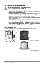
... oriented incorrectly. (Or you wish to set beyond the standard specifications, please do so according to GIGABYTE's website for the peripherals. Locate the alignment keys on the motherboard CPU socket and the notches on the CPU GA-EG31M-S2 Motherboard - 12 - It is not installed, otherwise overheating and damage of the CPU Socket Notch Notch Triangle...
... oriented incorrectly. (Or you wish to set beyond the standard specifications, please do so according to GIGABYTE's website for the peripherals. Locate the alignment keys on the motherboard CPU socket and the notches on the CPU GA-EG31M-S2 Motherboard - 12 - It is not installed, otherwise overheating and damage of the CPU Socket Notch Notch Triangle...
Manual
Page 13
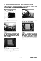
..., always replace the protective socket cover when the CPU is properly inserted, replace the load plate and push the CPU socket lever back into the motherboard CPU socket. CPU Socket Lever Step 1: Completely raise the CPU socket lever. Hardware Installation Step 5: Once the CPU is not installed.) Step 4: Hold the CPU...
..., always replace the protective socket cover when the CPU is properly inserted, replace the load plate and push the CPU socket lever back into the motherboard CPU socket. CPU Socket Lever Step 1: Completely raise the CPU socket lever. Hardware Installation Step 5: Once the CPU is not installed.) Step 4: Hold the CPU...
Manual
Page 14
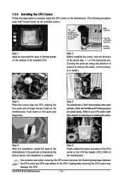
GA-EG31M-S2 Motherboard - 14 - Step 4: You should hear a "click" when pushing down on the push pins ... 5: After the installation, check the back of the CPU cooler to the CPU fan header (CPU_FAN) on the motherboard. Inadequately removing the CPU cooler may adhere to the CPU. 1-3-2 Installing the CPU Cooler Follow the steps below to... correctly install the CPU cooler on the motherboard. (The following procedure uses Intel® boxed cooler as the picture above, the installation is to install.) Step ...
GA-EG31M-S2 Motherboard - 14 - Step 4: You should hear a "click" when pushing down on the push pins ... 5: After the installation, check the back of the CPU cooler to the CPU fan header (CPU_FAN) on the motherboard. Inadequately removing the CPU cooler may adhere to the CPU. 1-3-2 Installing the CPU Cooler Follow the steps below to... correctly install the CPU cooler on the motherboard. (The following procedure uses Intel® boxed cooler as the picture above, the installation is to install.) Step ...
Manual
Page 15
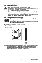
... read the following guidelines before installing the memory to insert the memory, switch the direction. 1-4-1 Dual Channel Memory Configuration This motherboard provides two DDR2 memory sockets and supports Dual Channel Technology. After the memory is recommended that memory of the memory. Hardware Installation... It is installed, the BIOS will double the original memory bandwidth. A memory module can be used . (Go to GIGABYTE's website for the latest memory support list.) • Always turn off the computer and unplug the power cord from the power outlet...
... read the following guidelines before installing the memory to insert the memory, switch the direction. 1-4-1 Dual Channel Memory Configuration This motherboard provides two DDR2 memory sockets and supports Dual Channel Technology. After the memory is recommended that memory of the memory. Hardware Installation... It is installed, the BIOS will double the original memory bandwidth. A memory module can be used . (Go to GIGABYTE's website for the latest memory support list.) • Always turn off the computer and unplug the power cord from the power outlet...
Manual
Page 16
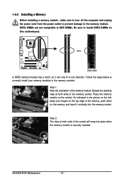
Notch DDR2 DIMM A DDR2 memory module has a notch, so it vertically into place when the memory module is securely inserted. GA-EG31M-S2 Motherboard - 16 - Follow the steps below to correctly install your fingers on the top edge of the memory socket. Spread the retaining clips at both ends ... , make sure to turn off the computer and unplug the power cord from the power outlet to prevent damage to install DDR2 DIMMs on this motherboard.
Notch DDR2 DIMM A DDR2 memory module has a notch, so it vertically into place when the memory module is securely inserted. GA-EG31M-S2 Motherboard - 16 - Follow the steps below to correctly install your fingers on the top edge of the memory socket. Spread the retaining clips at both ends ... , make sure to turn off the computer and unplug the power cord from the power outlet to prevent damage to install DDR2 DIMMs on this motherboard.
Manual
Page 17
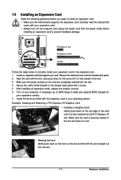
... turn off the computer and unplug the power cord from the power outlet before you begin to install an expansion card: • Make sure the motherboard supports the expansion card. PCI Express x1 Slot PCI Express x16 Slot PCI Slot Follow the steps below to correctly install your expansion card in...
... turn off the computer and unplug the power cord from the power outlet before you begin to install an expansion card: • Make sure the motherboard supports the expansion card. PCI Express x1 Slot PCI Express x16 Slot PCI Slot Follow the steps below to correctly install your expansion card in...
Manual
Page 18
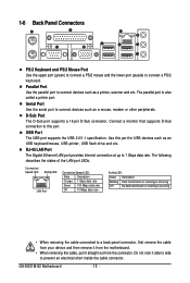
... devices such as a printer, scanner and etc. RJ-45 LAN Port The Gigabit Ethernet LAN port provides Internet connection at up to connect a PS/2 keyboard. GA-EG31M-S2 Motherboard - 18 - Serial Port Use the serial port to prevent an electrical short inside the cable connector. Parallel Port Use the parallel port to this port...
... devices such as a printer, scanner and etc. RJ-45 LAN Port The Gigabit Ethernet LAN port provides Internet connection at up to connect a PS/2 keyboard. GA-EG31M-S2 Motherboard - 18 - Serial Port Use the serial port to prevent an electrical short inside the cable connector. Parallel Port Use the parallel port to this port...
Manual
Page 20
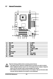
GA-EG31M-S2 Motherboard - 20 - 1-7 Internal Connectors 1 3 19 6 5 11 18 9 12 14 13 16 17 15 2 4 10 78 1) ATX_12V 2) ATX 3) CPU_FAN 4) SYS_FAN 5) FDD 6) IDE 7) SATA2_0/1/2/3 8) PWR_LED 9) BAT 10) F_PANEL ...) CD_IN 13) SPDIF_O 14) HDA_SUR 15) F_USB1/F_USB2 16) COMB 17) CI 18) CLR_CMOS 19) PHASE LED Read the following guidelines before turning on the motherboard. Unplug the power cord from the power outlet to prevent damage to the devices. • After installing the device and before connecting external devices: •...
GA-EG31M-S2 Motherboard - 20 - 1-7 Internal Connectors 1 3 19 6 5 11 18 9 12 14 13 16 17 15 2 4 10 78 1) ATX_12V 2) ATX 3) CPU_FAN 4) SYS_FAN 5) FDD 6) IDE 7) SATA2_0/1/2/3 8) PWR_LED 9) BAT 10) F_PANEL ...) CD_IN 13) SPDIF_O 14) HDA_SUR 15) F_USB1/F_USB2 16) COMB 17) CI 18) CLR_CMOS 19) PHASE LED Read the following guidelines before turning on the motherboard. Unplug the power cord from the power outlet to prevent damage to the devices. • After installing the device and before connecting external devices: •...
Manual
Page 21
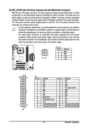
... sure the power supply is used (500W or greater). If a power supply is turned off and all the components on the motherboard. The 12V power connector mainly supplies power to an unstable or unbootable system. • The main power connector is recommended that ... power supply cable into pins under the protective cover when using a 2x12 power supply, remove the protective cover from the main power connector on the motherboard. The power connector possesses a foolproof design. When using a 2x10 power supply. 3 4 1 2 ATX_12V ATX_12V : Pin No. 1 2 3 4 Definition GND GND ...
... sure the power supply is used (500W or greater). If a power supply is turned off and all the components on the motherboard. The 12V power connector mainly supplies power to an unstable or unbootable system. • The main power connector is recommended that ... power supply cable into pins under the protective cover when using a 2x12 power supply, remove the protective cover from the main power connector on the motherboard. The power connector possesses a foolproof design. When using a 2x10 power supply. 3 4 1 2 ATX_12V ATX_12V : Pin No. 1 2 3 4 Definition GND GND ...
Manual
Page 22
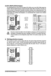
... Most fan headers possess a foolproof insertion design. For optimum heat dissipation, it in damage to connect a floppy disk drive. The motherboard supports CPU fan speed control, which requires the use of the connector and the floppy disk drive cable. Do not place a jumper... a 4-pin CPU fan header (CPU_FAN) and a 4-pin (SYS_FAN) system fan headers. The types of different color. 34 33 GA-EG31M-S2 Motherboard 2 1 - 22 - When connecting a fan cable, be installed inside the chassis. Definition 1 GND 1 2 +12V CPU_FAN 3 Sense 4 Speed Control 1 SYS_FAN SYS_FAN: Pin No. ...
... Most fan headers possess a foolproof insertion design. For optimum heat dissipation, it in damage to connect a floppy disk drive. The motherboard supports CPU fan speed control, which requires the use of the connector and the floppy disk drive cable. Do not place a jumper... a 4-pin CPU fan header (CPU_FAN) and a 4-pin (SYS_FAN) system fan headers. The types of different color. 34 33 GA-EG31M-S2 Motherboard 2 1 - 22 - When connecting a fan cable, be installed inside the chassis. Definition 1 GND 1 2 +12V CPU_FAN 3 Sense 4 Speed Control 1 SYS_FAN SYS_FAN: Pin No. ...
Manual
Page 24
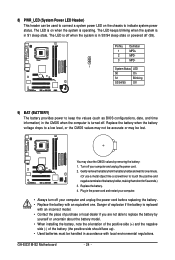
... (S5). You may be handled in S3/S4 sleep state or powered off . Gently remove the battery from the battery holder and wait for one . GA-EG31M-S2 Motherboard - 24 - Replace the battery when the battery voltage drops to a low level, or the CMOS values may not be accurate or may clear the CMOS...
... (S5). You may be handled in S3/S4 sleep state or powered off . Gently remove the battery from the battery holder and wait for one . GA-EG31M-S2 Motherboard - 24 - Replace the battery when the battery voltage drops to a low level, or the CMOS values may not be accurate or may clear the CMOS...


