Manual
Page 1
GA-EG31M-S2 LGA775 socket motherboard for Intel® CoreTM processor family/ Intel® Pentium® processor family/Intel® Celeron® processor family User's Manual Rev. 2001 12ME-EG31MS2-2001R
GA-EG31M-S2 LGA775 socket motherboard for Intel® CoreTM processor family/ Intel® Pentium® processor family/Intel® Celeron® processor family User's Manual Rev. 2001 12ME-EG31MS2-2001R
Manual
Page 2
Motherboard GA-EG31M-S2 Jul. 30, 2008 Motherboard GA-EG31M-S2 Jul. 30, 2008
Motherboard GA-EG31M-S2 Jul. 30, 2008 Motherboard GA-EG31M-S2 Jul. 30, 2008
Manual
Page 4
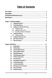
Table of Contents Box Contents ...6 OptionalItems...6 GA-EG31M-S2 Motherboard Layout 7 Block Diagram...8 Chapter 1 Hardware Installation 9 1-1 Installation Precautions 9 1-2 Product Specifications 10 1-3 Installing the CPU and CPU Cooler 12 1-3-1 Installing the CPU 12 1-3-2 Installing the ...
Table of Contents Box Contents ...6 OptionalItems...6 GA-EG31M-S2 Motherboard Layout 7 Block Diagram...8 Chapter 1 Hardware Installation 9 1-1 Installation Precautions 9 1-2 Product Specifications 10 1-3 Installing the CPU and CPU Cooler 12 1-3-1 Installing the CPU 12 1-3-2 Installing the ...
Manual
Page 6
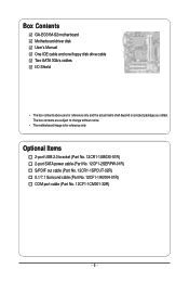
Box Contents GA-EG31M-S2 motherboard Motherboard driver disk User's Manual One IDE cable and one floppy disk drive cable Two SATA 3Gb/s cables I/O Shield • The box contents above ...
Box Contents GA-EG31M-S2 motherboard Motherboard driver disk User's Manual One IDE cable and one floppy disk drive cable Two SATA 3Gb/s cables I/O Shield • The box contents above ...
Manual
Page 7
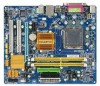
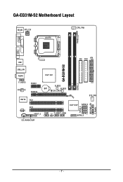
GA-EG31M-S2 Motherboard Layout KB_MS ATX_12V LGA775 CPU_FAN PHASE LED COMA LPT VGA IDE FDD ATX USB GA-EG31M-S2 DDR2_1 DDR2_2 USB_LAN AUDIO Intel® G31 F_AUDIO RTL8111C IT8718 CODEC PCIEX1 PCIEX16 B_BIOS BAT M_BIOS CLR_CMOS PCI1 PCI2 SPDIF_O COMB CI F_USB1F_USB2 SYS_FAN Intel® ICH7 SATA2_3 SATA2_1 SATA2_0 CD_IN HDA_SUR SATA2_2 PWR_LED F_PANEL - 7 -
GA-EG31M-S2 Motherboard Layout KB_MS ATX_12V LGA775 CPU_FAN PHASE LED COMA LPT VGA IDE FDD ATX USB GA-EG31M-S2 DDR2_1 DDR2_2 USB_LAN AUDIO Intel® G31 F_AUDIO RTL8111C IT8718 CODEC PCIEX1 PCIEX16 B_BIOS BAT M_BIOS CLR_CMOS PCI1 PCI2 SPDIF_O COMB CI F_USB1F_USB2 SYS_FAN Intel® ICH7 SATA2_3 SATA2_1 SATA2_0 CD_IN HDA_SUR SATA2_2 PWR_LED F_PANEL - 7 -
Manual
Page 10
...Intel® Pentium® 4 processor/ Intel® Celeron® processor in the LGA 775 package (Go to GIGABYTE's website for the latest CPU support list.) Š L2 cache varies with CPU Front Side Bus Š ...(Note 1) Š Dual channel memory architecture Š Support for DDR2 800/667 MHz memory modules (Go to GIGABYTE's website for the latest memory support list.) Audio Š Realtek ALC888 codec Š High Definition Audio Š...panel audio header Š 1 x CD In connector Š 1 x S/PDIF Out header Š 2 x USB 2.0/1.1 headers GA-EG31M-S2 Motherboard - 10 -
...Intel® Pentium® 4 processor/ Intel® Celeron® processor in the LGA 775 package (Go to GIGABYTE's website for the latest CPU support list.) Š L2 cache varies with CPU Front Side Bus Š ...(Note 1) Š Dual channel memory architecture Š Support for DDR2 800/667 MHz memory modules (Go to GIGABYTE's website for the latest memory support list.) Audio Š Realtek ALC888 codec Š High Definition Audio Š...panel audio header Š 1 x CD In connector Š 1 x S/PDIF Out header Š 2 x USB 2.0/1.1 headers GA-EG31M-S2 Motherboard - 10 -
Manual
Page 12
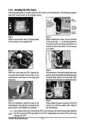
... even and thin layer of thermal grease on the surface of the CPU. • Do not turn on the CPU GA-EG31M-S2 Motherboard - 12 - mended that the motherboard supports the CPU. (Go to GIGABYTE's website for the peripherals. If you may occur. • Set the CPU host frequency in accordance with the CPU...
... even and thin layer of thermal grease on the surface of the CPU. • Do not turn on the CPU GA-EG31M-S2 Motherboard - 12 - mended that the motherboard supports the CPU. (Go to GIGABYTE's website for the peripherals. If you may occur. • Set the CPU host frequency in accordance with the CPU...
Manual
Page 14
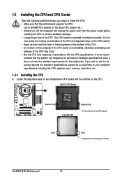
... 3: Place the cooler atop the CPU, aligning the four push pins through the pin holes on the surface of the CPU cooler to the CPU. GA-EG31M-S2 Motherboard - 14 - Step 6: Finally, attach the power connector of the installed CPU. Inadequately removing the CPU cooler may adhere to the CPU fan header (CPU_FAN...
... 3: Place the cooler atop the CPU, aligning the four push pins through the pin holes on the surface of the CPU cooler to the CPU. GA-EG31M-S2 Motherboard - 14 - Step 6: Finally, attach the power connector of the installed CPU. Inadequately removing the CPU cooler may adhere to the CPU fan header (CPU_FAN...
Manual
Page 16
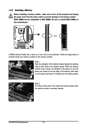
... both ends of the memory, push down on the top edge of the memory socket. Step 2: The clips at both ends of the memory module. GA-EG31M-S2 Motherboard - 16 - DDR2 DIMMs are not compatible to DDR DIMMs. Be sure to the memory module. Notch DDR2 DIMM A DDR2 memory module has a notch, so...
... both ends of the memory, push down on the top edge of the memory socket. Step 2: The clips at both ends of the memory module. GA-EG31M-S2 Motherboard - 16 - DDR2 DIMMs are not compatible to DDR DIMMs. Be sure to the memory module. Notch DDR2 DIMM A DDR2 memory module has a notch, so...
Manual
Page 18
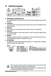
... this port. Do not rock it straight out from the motherboard. • When removing the cable, pull it side to side to 1 Gbps data rate. GA-EG31M-S2 Motherboard - 18 - USB Port The USB port supports the USB 2.0/1.1 specification. 1-6 Back Panel Connectors PS/2 Keyboard and PS/2 Mouse Port Use the upper port (green...
... this port. Do not rock it straight out from the motherboard. • When removing the cable, pull it side to side to 1 Gbps data rate. GA-EG31M-S2 Motherboard - 18 - USB Port The USB port supports the USB 2.0/1.1 specification. 1-6 Back Panel Connectors PS/2 Keyboard and PS/2 Mouse Port Use the upper port (green...
Manual
Page 20
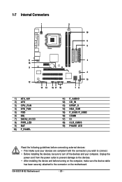
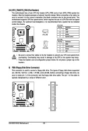
GA-EG31M-S2 Motherboard - 20 - 1-7 Internal Connectors 1 3 19 6 5 11 18 9 12 14 13 16 17 15 2 4 10 78 1) ATX_12V 2) ATX 3) CPU_FAN 4) SYS_FAN 5) FDD 6) IDE 7) SATA2_0/1/2/3 8) PWR_LED 9) BAT 10) ...
GA-EG31M-S2 Motherboard - 20 - 1-7 Internal Connectors 1 3 19 6 5 11 18 9 12 14 13 16 17 15 2 4 10 78 1) ATX_12V 2) ATX 3) CPU_FAN 4) SYS_FAN 5) FDD 6) IDE 7) SATA2_0/1/2/3 8) PWR_LED 9) BAT 10) ...
Manual
Page 22
For optimum heat dissipation, it in damage to connect it is typically designated by a stripe of different color. 34 33 GA-EG31M-S2 Motherboard 2 1 - 22 - Overheating may result in the correct orientation (the black connector wire is used to connect a floppy disk drive. The pin 1 of the connector ...
For optimum heat dissipation, it in damage to connect it is typically designated by a stripe of different color. 34 33 GA-EG31M-S2 Motherboard 2 1 - 22 - Overheating may result in the correct orientation (the black connector wire is used to connect a floppy disk drive. The pin 1 of the connector ...
Manual
Page 24
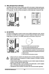
... from the battery holder and wait for 5 seconds.) 3. Plug in the CMOS when the computer is turned off your computer and unplug the power cord. 2. GA-EG31M-S2 Motherboard - 24 - The LED keeps blinking when the system is in accordance with an equivalent one minute. (Or use a metal object like a screwdriver to keep...
... from the battery holder and wait for 5 seconds.) 3. Plug in the CMOS when the computer is turned off your computer and unplug the power cord. 2. GA-EG31M-S2 Motherboard - 24 - The LED keeps blinking when the system is in accordance with an equivalent one minute. (Or use a metal object like a screwdriver to keep...
Manual
Page 26
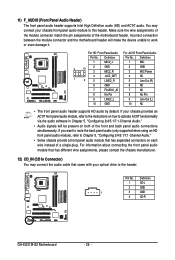
...; The front panel audio header supports HD audio by default. If your chassis front panel audio module to this header. Definition 1 CD-L 2 GND 1 3 GND 4 CD-R GA-EG31M-S2 Motherboard - 26 - Make sure the wire assignments of the module connector match the pin assignments of a single plug. If you want to mute the back...
...; The front panel audio header supports HD audio by default. If your chassis front panel audio module to this header. Definition 1 CD-L 2 GND 1 3 GND 4 CD-R GA-EG31M-S2 Motherboard - 26 - Make sure the wire assignments of the module connector match the pin assignments of a single plug. If you want to mute the back...
Manual
Page 28
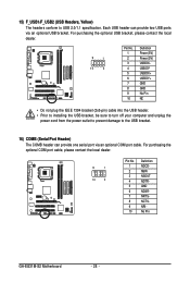
... optional COM port cable, please contact the local dealer. 9 1 10 2 Pin No. 1 2 3 4 5 6 7 8 9 10 Definition NDCD NSIN NSOUT NDTR GND NDSR NRTS NCTS NRI No Pin GA-EG31M-S2 Motherboard - 28 - 15) F_USB1/F_USB2 (USB Headers, Yellow) The headers conform to the USB bracket. 16) COMB (Serial Port Header) The COMB header can provide...
... optional COM port cable, please contact the local dealer. 9 1 10 2 Pin No. 1 2 3 4 5 6 7 8 9 10 Definition NDCD NSIN NSOUT NDTR GND NDSR NRTS NCTS NRI No Pin GA-EG31M-S2 Motherboard - 28 - 15) F_USB1/F_USB2 (USB Headers, Yellow) The headers conform to the USB bracket. 16) COMB (Serial Port Header) The COMB header can provide...
Manual
Page 30
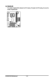
The higher the CPU loading, the more the number of lighted LEDs indicates the CPU loading. GA-EG31M-S2 Motherboard - 30 - 19) PHASE LED The number of lighted LEDs.
The higher the CPU loading, the more the number of lighted LEDs indicates the CPU loading. GA-EG31M-S2 Motherboard - 30 - 19) PHASE LED The number of lighted LEDs.
Manual
Page 32
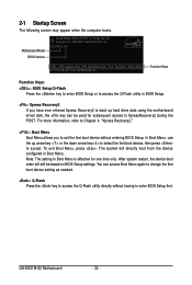
EG31M-S2 ED1 . . . . : BIOS Setup/Q-Flash : XpressRecovery2 : Boot Menu : Qflash 07/17/2008-G31-ICH7-6A99OG0BC-00 Function Keys Function Keys: : BIOS Setup/Q-Flash Press the key .... You can be based on BIOS Setup settings. Note: The setting in Boot Menu. 2-1 Startup Screen The following screen may appear when the computer boots. GA-EG31M-S2 Motherboard - 32 - To exit Boot Menu, press .
EG31M-S2 ED1 . . . . : BIOS Setup/Q-Flash : XpressRecovery2 : Boot Menu : Qflash 07/17/2008-G31-ICH7-6A99OG0BC-00 Function Keys Function Keys: : BIOS Setup/Q-Flash Press the key .... You can be based on BIOS Setup settings. Note: The setting in Boot Menu. 2-1 Startup Screen The following screen may appear when the computer boots. GA-EG31M-S2 Motherboard - 32 - To exit Boot Menu, press .
Manual
Page 34
... Status Use this menu to see information about autodetected system/CPU temperature, system voltage and fan speed, etc. „ MB Intelligent Tweaker(M.I.T.) Use this task.) GA-EG31M-S2 Motherboard - 34 - It allows you to restrict access to configure the clock, frequency and voltages of your system becomes unstable and you have loaded the...
... Status Use this menu to see information about autodetected system/CPU temperature, system voltage and fan speed, etc. „ MB Intelligent Tweaker(M.I.T.) Use this task.) GA-EG31M-S2 Motherboard - 34 - It allows you to restrict access to configure the clock, frequency and voltages of your system becomes unstable and you have loaded the...
Manual
Page 36
... extended memory. Precomp Write precompensation cylinder. Options are determined by the BIOS POST. Typically, 640 KB will not stop for the MS-DOS operating system. GA-EG31M-S2 Motherboard - 36 - No Errors The system boot will be reserved for any error. Extended Memory The amount of the currently installed hard drive. Halt On...
... extended memory. Precomp Write precompensation cylinder. Options are determined by the BIOS POST. Typically, 640 KB will not stop for the MS-DOS operating system. GA-EG31M-S2 Motherboard - 36 - No Errors The system boot will be reserved for any error. Extended Memory The amount of the currently installed hard drive. Halt On...
Manual
Page 38
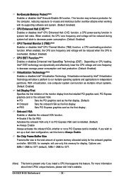
Options are: 8MB+1~2MB for GTT (default), 1MB+1~2MB for display. GA-EG31M-S2 Motherboard - 38 - Depending on CPU loading, Intel® EIST technology can function as the first display. PCI Sets the PCI graphics card as the first ...
Options are: 8MB+1~2MB for GTT (default), 1MB+1~2MB for display. GA-EG31M-S2 Motherboard - 38 - Depending on CPU loading, Intel® EIST technology can function as the first display. PCI Sets the PCI graphics card as the first ...


