
Manual
Page 3
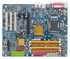
... Peripherals menu and then press ENTER. VIA VT6410 IDE RAID Drives Configuration (2) Configuring VT6410 IDE controller mode and boot sequence in system BIOS Setup and set this option to Disabled, the VT6410 IDE controller will be disabled and will not support any devices. Step 1: Turn on your computer and press the Del key to USB Controller USB 2.0 Controller USB Keyboard Support USB Mouse Support Azalia Codec Onboard H/W RAID Onboard H/W 1394 Onboard H/W LAN1 Onboard H/W LAN2 Onboard LAN1 Boot ROM Onboard LAN2 Boot ROM Onboard Serial Port 1 Onboard IrDA Port [Enabled] [RAID] Auto Ch...
... Peripherals menu and then press ENTER. VIA VT6410 IDE RAID Drives Configuration (2) Configuring VT6410 IDE controller mode and boot sequence in system BIOS Setup and set this option to Disabled, the VT6410 IDE controller will be disabled and will not support any devices. Step 1: Turn on your computer and press the Del key to USB Controller USB 2.0 Controller USB Keyboard Support USB Mouse Support Azalia Codec Onboard H/W RAID Onboard H/W 1394 Onboard H/W LAN1 Onboard H/W LAN2 Onboard LAN1 Boot ROM Onboard LAN2 Boot ROM Onboard Serial Port 1 Onboard IrDA Port [Enabled] [RAID] Auto Ch...
Manual
Page 4
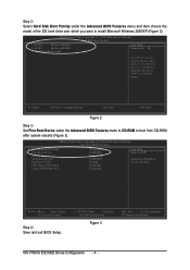
...-2004 Award Software Hard Disk Boot Priority ¤å 1. CMOS Setup Utility-Copyright (C) 1984-2004 Award Software Advanced BIOS Features ` Hard Disk Boot Priority First Boot Device Second Boot Device Third Boot Device Password Check CPU Hyper-Threading Limit CPUID Max. KL: Move PU/PD/+/-: Change Priority F10: Save ESC: Exit Figure 2 Step 3: Set First Boot Device under the Advanced BIOS Features menu and then choose the Åé model of the IDE hard drive onto which you want to 3 [Press Enter] [CDROM] [Hard Disk] [CDROM] [Setup] [Enabled] [Enabled...
...-2004 Award Software Hard Disk Boot Priority ¤å 1. CMOS Setup Utility-Copyright (C) 1984-2004 Award Software Advanced BIOS Features ` Hard Disk Boot Priority First Boot Device Second Boot Device Third Boot Device Password Check CPU Hyper-Threading Limit CPUID Max. KL: Move PU/PD/+/-: Change Priority F10: Save ESC: Exit Figure 2 Step 3: Set First Boot Device under the Advanced BIOS Features menu and then choose the Åé model of the IDE hard drive onto which you want to 3 [Press Enter] [CDROM] [Hard Disk] [CDROM] [Setup] [Enabled] [Enabled...
Manual
Page 10
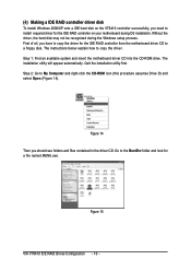
... VIA VT6410 IDE RAID Drives Configuration - 10 - First of all, you should see folders and files contained in the driver CD. Figure 14 Then you have to copy the driver for the IDE RAID controller from the motherboard driver CD to install required driver for a file named MENU.exe. Step 1: Find an available system and insert the motherboard driver CD into the CD-ROM drive. Quit the installation utility first. The installation utility will...
... VIA VT6410 IDE RAID Drives Configuration - 10 - First of all, you should see folders and files contained in the driver CD. Figure 14 Then you have to copy the driver for the IDE RAID controller from the motherboard driver CD to install required driver for a file named MENU.exe. Step 1: Find an available system and insert the motherboard driver CD into the CD-ROM drive. Quit the installation utility first. The installation utility will...
Manual
Page 12
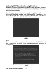
... a device support disk from the Windows 2000/XP Setup disk and press F6 as soon as you see the next screen for use with Windows, press ENTER. Then you will be asked to select the IDE RAID controller on your motherboard. After pressing the F6 key, there will be a few moments of one or more mass storage devices installed in your motherboard. Windows Setup Setup could not determine the type of some files being loaded...
... a device support disk from the Windows 2000/XP Setup disk and press F6 as soon as you see the next screen for use with Windows, press ENTER. Then you will be asked to select the IDE RAID controller on your motherboard. After pressing the F6 key, there will be a few moments of one or more mass storage devices installed in your motherboard. Windows Setup Setup could not determine the type of some files being loaded...
Manual
Page 11
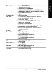
...; Supports ATAPI mode for HDD Š Supports IDE bus master operation Š Displays status and error checking messages during boot-up Š Mirroring supports automatic background rebuilds Š Features LBA and Extended Interrupt 13 drive translation in controller onboard BIOS Š IT8712 Š System voltage detection Š CPU temperature detection Š CPU / System / Power fan speed detection Š CPU warning temperature Š CPU / System / Power fan failure warning Š CPU smart fan control Š Use of licensed AWARD BIOS Š Supports Q-Flash Š Supports @BIOS...
...; Supports ATAPI mode for HDD Š Supports IDE bus master operation Š Displays status and error checking messages during boot-up Š Mirroring supports automatic background rebuilds Š Features LBA and Extended Interrupt 13 drive translation in controller onboard BIOS Š IT8712 Š System voltage detection Š CPU temperature detection Š CPU / System / Power fan speed detection Š CPU warning temperature Š CPU / System / Power fan failure warning Š CPU smart fan control Š Use of licensed AWARD BIOS Š Supports Q-Flash Š Supports @BIOS...
Manual
Page 21
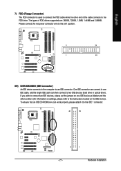
... connect two IDE devices, please set the jumper on the IDE device). English 7) FDD (Floppy Connector) The FDD connector is used to connect the FDD cable while the other as Master and the other end of FDD drives supported are: 360KB, 720KB, 1.2MB, 1.44MB and 2.88MB. One IDE connector can connect to one IDE device as Slave (for information on settings, please refer to the instructions located on one IDE cable, and the single IDE cable can work...
... connect two IDE devices, please set the jumper on the IDE device). English 7) FDD (Floppy Connector) The FDD connector is used to connect the FDD cable while the other as Master and the other end of FDD drives supported are: 360KB, 720KB, 1.2MB, 1.44MB and 2.88MB. One IDE connector can connect to one IDE device as Slave (for information on settings, please refer to the instructions located on one IDE cable, and the single IDE cable can work...

Manual
Page 22
Definition 1 1 MPD+ 2 MPD- 3 MPD- English 10) S_ATA0/S_ATA1/S_ATA2/S_ATA3 (Serial ATA Connector) Serial ATA can provide 150MB/s transfer rate. It will blink when the system enters suspend mode. GA-8I915G Duo Motherboard - 22 - Pin No. Please refer to the BIOS setting for the Serial ATA and install the proper driver in order to indicate whether the system is connect with the system power indicator to work properly. Definition 1 GND 7 1 2 TXP 3 TXN 4 GND 5 RXN 6 RXP 7 GND 11) PWR_LED PWR_LED is on/off. Pin No.
Definition 1 1 MPD+ 2 MPD- 3 MPD- English 10) S_ATA0/S_ATA1/S_ATA2/S_ATA3 (Serial ATA Connector) Serial ATA can provide 150MB/s transfer rate. It will blink when the system enters suspend mode. GA-8I915G Duo Motherboard - 22 - Pin No. Please refer to the BIOS setting for the Serial ATA and install the proper driver in order to indicate whether the system is connect with the system power indicator to work properly. Definition 1 GND 7 1 2 TXP 3 TXN 4 GND 5 RXN 6 RXP 7 GND 11) PWR_LED PWR_LED is on/off. Pin No.
Manual
Page 30
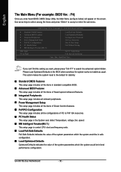
...CMOS Setup Utility-Copyright (C) 1984-2004 Award Software ` Standard CMOS Features ` Advanced BIOS Features ` Integrated Peripherals ` Power Management Setup ` PnP/PCI Configurations ` PC Health Status ` MB Intelligent Tweaker(M.I .T.) This setup page is the System auto detect Temperature, voltage, fan, speed. „ MB Intelligent Tweaker(M.I .T.) ESC: Quit F8: Q-Flash Load Fail-Safe Defaults Load Optimized Defaults Set Supervisor Password Set User Password Save & Exit Setup Exit Without Saving KLJI: Select Item F10: Save & Exit Setup Time, Date, Hard Disk Type... GA-8I915G Duo Motherboard...
...CMOS Setup Utility-Copyright (C) 1984-2004 Award Software ` Standard CMOS Features ` Advanced BIOS Features ` Integrated Peripherals ` Power Management Setup ` PnP/PCI Configurations ` PC Health Status ` MB Intelligent Tweaker(M.I .T.) This setup page is the System auto detect Temperature, voltage, fan, speed. „ MB Intelligent Tweaker(M.I .T.) ESC: Quit F8: Q-Flash Load Fail-Safe Defaults Load Optimized Defaults Set Supervisor Password Set User Password Save & Exit Setup Exit Without Saving KLJI: Select Item F10: Save & Exit Setup Time, Date, Hard Disk Type... GA-8I915G Duo Motherboard...
Manual
Page 32
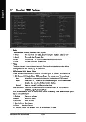
... BIOS to set the access mode for the hard drive. The time is , , , . You can manually input the correct settings Access Mode Use this option for faster system start up. The four options are used and the system will skip the automatic detection step and allow for automatic device detection. GA-8I915G Duo Motherboard - 32 - to Dec. 1 to 31 (or maximum allowed in the month) Base Memory Extended Memory Total Memory KLJI: Move Enter...
... BIOS to set the access mode for the hard drive. The time is , , , . You can manually input the correct settings Access Mode Use this option for faster system start up. The four options are used and the system will skip the automatic detection step and allow for automatic device detection. GA-8I915G Duo Motherboard - 32 - to Dec. 1 to 31 (or maximum allowed in the month) Base Memory Extended Memory Total Memory KLJI: Move Enter...
Manual
Page 43
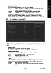
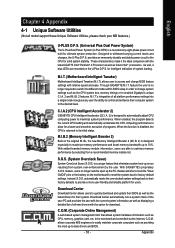
... For power end-user use a CPU fan with a 4-pin fan power cable. Robust Graphics Booster Select the options can be used for it. (Default Value) Voltage Set to Voltage when you installed and sets the optimal CPU Smart FAN control mode for CPU fans with a 3-pin fan power cable. Disabled Disable this function. (Default value) Cruise Set C.I.A.2 to Cruise. (Automatically increase CPU frequency(5%,7%) by CPU detection. The option will not effectively reduce the fan speed. 2-7 MB Intelligent Tweaker(M.I.T.) CMOS Setup Utility-Copyright (C) 1984-2004 Award Software...
... For power end-user use a CPU fan with a 4-pin fan power cable. Robust Graphics Booster Select the options can be used for it. (Default Value) Voltage Set to Voltage when you installed and sets the optimal CPU Smart FAN control mode for CPU fans with a 3-pin fan power cable. Disabled Disable this function. (Default value) Cruise Set C.I.A.2 to Cruise. (Automatically increase CPU frequency(5%,7%) by CPU detection. The option will not effectively reduce the fan speed. 2-7 MB Intelligent Tweaker(M.I.T.) CMOS Setup Utility-Copyright (C) 1984-2004 Award Software...
Manual
Page 46
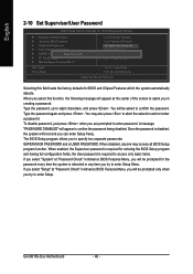
... defaults for the password every time the system is required to enter password. English 2-10 Set Supervisor/User Password CMOS Setup Utility-Copyright (C) 1984-2004 Award Software ` Standard CMOS Features ` Advanced BIOS Features ` Integrated Peripherals ` Power Management Setup ` PnP/PCI ConfigurationEsnter Password: ` PC Health Status ` MB Intelligent Tweaker(M.I.T.) Load Fail-Safe Defaults Load Optimized Defaults Set Supervisor Password Set User Password Save & Exit Setup Exit Without Saving ESC: Quit F8: Q-Flash KLJI: Select Item F10: Save & Exit Setup Change/Set/Disable Password...
... defaults for the password every time the system is required to enter password. English 2-10 Set Supervisor/User Password CMOS Setup Utility-Copyright (C) 1984-2004 Award Software ` Standard CMOS Features ` Advanced BIOS Features ` Integrated Peripherals ` Power Management Setup ` PnP/PCI ConfigurationEsnter Password: ` PC Health Status ` MB Intelligent Tweaker(M.I.T.) Load Fail-Safe Defaults Load Optimized Defaults Set Supervisor Password Set User Password Save & Exit Setup Exit Without Saving ESC: Quit F8: Q-Flash KLJI: Select Item F10: Save & Exit Setup Change/Set/Disable Password...
Manual
Page 49
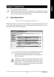
... CD-ROM drive, the driver CD-title will show the installation guide. After install Windows Service Pack, it will auto start and show a question mark "?" or you want and press "install" followed the item; Insert the driver CD-title that came with your motherboard into your system automatically. in Windows XP. English Chapter 3 Install Drivers Pictures below are shown in "Universal Serial Bus controller" under Windows XP operating system, please use Windows Service...
... CD-ROM drive, the driver CD-title will show the installation guide. After install Windows Service Pack, it will auto start and show a question mark "?" or you want and press "install" followed the item; Insert the driver CD-title that came with your motherboard into your system automatically. in Windows XP. English Chapter 3 Install Drivers Pictures below are shown in "Universal Serial Bus controller" under Windows XP operating system, please use Windows Service...
Manual
Page 53
... is disabled, the CPU is no longer need to open up the PC chassis and short-circuit the "Clear CMOS" pins or the battery on the motherboard to reset the system back to enabled Gigabyte's unique C.I.A. 2 and M.I .A. 2) is designed especially to maximize memory performance and boost memory bandwidth up errors resulting from system over-enhancement by selecting from a recommended memory module list. feature, users no longer required to switch...
... is disabled, the CPU is no longer need to open up the PC chassis and short-circuit the "Clear CMOS" pins or the battery on the motherboard to reset the system back to enabled Gigabyte's unique C.I.A. 2 and M.I .A. 2) is designed especially to maximize memory performance and boost memory bandwidth up errors resulting from system over-enhancement by selecting from a recommended memory module list. feature, users no longer required to switch...
Manual
Page 58
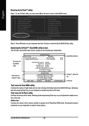
...-2004 Award Software Standard CMOS Features Advanced BIOS Features Integrated Peripherals Power Management Setup PnP/PCI Configurations PC Health Status MB Intelligent Tweaker(M.I.T.) ESC: Quit F8: Dual BIOS/Q-Flash Select Language Load Fail-Safe Defaults Load Optimized Defaults Set Supervisor Password Set User Password Save & Exit Setup Exit Without Saving F3: Change Language F10: Save & Exit Setup Time, Date, Hard Disk Type... Task menu for Dual BIOS utility Task menu for Q-FlashTM utility Dual BIOS Utility Boot From Main Bios Main ROM Type/Size SST 49LF004A Backup ROM Type/Size SST...
...-2004 Award Software Standard CMOS Features Advanced BIOS Features Integrated Peripherals Power Management Setup PnP/PCI Configurations PC Health Status MB Intelligent Tweaker(M.I.T.) ESC: Quit F8: Dual BIOS/Q-Flash Select Language Load Fail-Safe Defaults Load Optimized Defaults Set Supervisor Password Set User Password Save & Exit Setup Exit Without Saving F3: Change Language F10: Save & Exit Setup Time, Date, Hard Disk Type... Task menu for Dual BIOS utility Task menu for Q-FlashTM utility Dual BIOS Utility Boot From Main Bios Main ROM Type/Size SST 49LF004A Backup ROM Type/Size SST...
Manual
Page 64
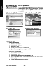
... steps: I. Click "Update New BIOS" icon c. Click "Update New BIOS" c. GA-8I915G Duo Motherboard - 64 - The @BIOS Utility Click " " Click "Update New BIOS" Fig 4. Update BIOS through Internet: a. Select @BIOSTM sever d. Select the exact model name on your motherboard e. II. Please select "All Files" in dialog box while opening the old file. Complete update process following the instruction. Installing the @BIOS utility Fig 2. Update BIOS NOT through Internet a. Please search for BIOS unzip file, downloading from internet or...
... steps: I. Click "Update New BIOS" icon c. Click "Update New BIOS" c. GA-8I915G Duo Motherboard - 64 - The @BIOS Utility Click " " Click "Update New BIOS" Fig 4. Update BIOS through Internet: a. Select @BIOSTM sever d. Select the exact model name on your motherboard e. II. Please select "All Files" in dialog box while opening the old file. Complete update process following the instruction. Installing the @BIOS utility Fig 2. Update BIOS NOT through Internet a. Please search for BIOS unzip file, downloading from internet or...
Manual
Page 67
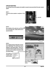
... the function. STEP 1: Connect the stereo speakers or earphone to acquire the best sound effect if the stereo output is displayed in the system area. English 2 Channel Audio Setup: We recommend that you use speakers with amplifier to "Line Out". Line Out STEP 2: After installation of the audio driver, you the functions to manually modify speaker settings. "Smart Jack" would auto-detect the speaker type you connect and gives you...
... the function. STEP 1: Connect the stereo speakers or earphone to acquire the best sound effect if the stereo output is displayed in the system area. English 2 Channel Audio Setup: We recommend that you use speakers with amplifier to "Line Out". Line Out STEP 2: After installation of the audio driver, you the functions to manually modify speaker settings. "Smart Jack" would auto-detect the speaker type you connect and gives you...
Manual
Page 68
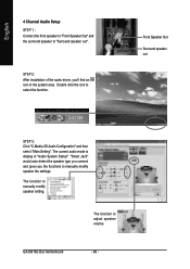
... audio driver, you the functions to manually modify speaker the settings. The current audio mode is display in the system area. GA-8I915G Duo Motherboard - 68 - English 4 Channel Audio Setup STEP 1 : Connect the front speaker to "Front Speaker Out" and the surround speaker to select the function. Double click the icon to "Surround speaker out". The function to manually modify speaker setting. Front Speaker Out Surround speaker out STEP 3: Click "C-Media 3D Audio Configuration" and then select "Main Setting...
... audio driver, you the functions to manually modify speaker the settings. The current audio mode is display in the system area. GA-8I915G Duo Motherboard - 68 - English 4 Channel Audio Setup STEP 1 : Connect the front speaker to "Front Speaker Out" and the surround speaker to select the function. Double click the icon to "Surround speaker out". The function to manually modify speaker setting. Front Speaker Out Surround speaker out STEP 3: Click "C-Media 3D Audio Configuration" and then select "Main Setting...
Manual
Page 69
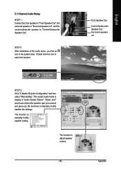
... 3: Click "C-Media 3D Audio Configuration" and then select "Main Setting". The function to manually modify speaker the settings. STEP 2: After installation of the audio driver, you the functions to adjust speaker volume. - 69 - "Smart Jack" would auto-detect the speaker type you connect and gives you find an icon in "Audio System Status". English 5.1 Channel Audio Setup STEP 1 : Connect the front speaker to "Front Speaker Out", the surround speaker to "Surround speaker out", and the...
... 3: Click "C-Media 3D Audio Configuration" and then select "Main Setting". The function to manually modify speaker the settings. STEP 2: After installation of the audio driver, you the functions to adjust speaker volume. - 69 - "Smart Jack" would auto-detect the speaker type you connect and gives you find an icon in "Audio System Status". English 5.1 Channel Audio Setup STEP 1 : Connect the front speaker to "Front Speaker Out", the surround speaker to "Surround speaker out", and the...
Manual
Page 70
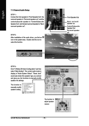
The current audio mode is display in the system area. GA-8I915G Duo Motherboard - 70 - Front Speaker Out Back surround speaker out Center/Subwoofer Speaker Out Surround speaker out STEP 3: Click "C-Media 3D Audio Configuration" and then select "Main Setting". The function to adjust speaker volume. The function to manually modify speaker setting. "Smart Jack" would auto-detect the speaker type you connect and gives you find an icon in "Audio System Status". Double click the...
The current audio mode is display in the system area. GA-8I915G Duo Motherboard - 70 - Front Speaker Out Back surround speaker out Center/Subwoofer Speaker Out Surround speaker out STEP 3: Click "C-Media 3D Audio Configuration" and then select "Main Setting". The function to adjust speaker volume. The function to manually modify speaker setting. "Smart Jack" would auto-detect the speaker type you connect and gives you find an icon in "Audio System Status". Double click the...
Manual
Page 72
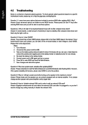
... you can use a metal object to connect the positive and negative pins in the battery holder to http://tw.giga-byte.com/faq/faq.htm Question 1: I still get a weak sound after turning up the speaker to load Fail-Safe Defaults (Or Load BIOS Defaults) after flashing BIOS. Answer: In some options that 's why the light is plugged in, so you are hidden in new BIOS version. If your board has a Clear CMOS jumper, please refer...
... you can use a metal object to connect the positive and negative pins in the battery holder to http://tw.giga-byte.com/faq/faq.htm Question 1: I still get a weak sound after turning up the speaker to load Fail-Safe Defaults (Or Load BIOS Defaults) after flashing BIOS. Answer: In some options that 's why the light is plugged in, so you are hidden in new BIOS version. If your board has a Clear CMOS jumper, please refer...


