Manual
Page 2
... the VT6410 controller, you may prepare only one hard drive. (b) An empty formatted floppy disk. (c) Windows XP/2000 setup disk. (d) Driver CD for your motherboard. (1) Installing IDE hard drive(s) in your system Attach one end of the IDE cable to the rear of the IDE hard drive and the other... the IDE RAID controller driver (5) Install the IDE RAID controller driver during OS installation. If you do not want to create RAID.array on the motherboard. (To ensure that you have to follow the steps below: ¤å (1) Install IDE hard drive(s) in your power supply to create RAID with...
... the VT6410 controller, you may prepare only one hard drive. (b) An empty formatted floppy disk. (c) Windows XP/2000 setup disk. (d) Driver CD for your motherboard. (1) Installing IDE hard drive(s) in your system Attach one end of the IDE cable to the rear of the IDE hard drive and the other... the IDE RAID controller driver (5) Install the IDE RAID controller driver during OS installation. If you do not want to create RAID.array on the motherboard. (To ensure that you have to follow the steps below: ¤å (1) Install IDE hard drive(s) in your power supply to create RAID with...
Manual
Page 10
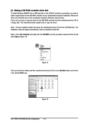
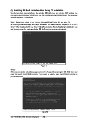
...right-click the CD-ROM icon (this procedure assumes Drive D) and select Open (Figure 14). Step 1: Find an available system and insert the motherboard driver CD into the CD-ROM drive. Step 2: Go to copy the driver. Go to the BootDrv folder and look for a file named ...MENU.exe. The installation utility will appear automatically. Figure 14 Then you have to copy the driver for the IDE RAID controller from the motherboard driver CD to ¤å a floppy disk. Ác (4) Making a IDE RAID controller driver disk Åé To install Windows 2000/XP onto ...
...right-click the CD-ROM icon (this procedure assumes Drive D) and select Open (Figure 14). Step 1: Find an available system and insert the motherboard driver CD into the CD-ROM drive. Step 2: Go to copy the driver. Go to the BootDrv folder and look for a file named ...MENU.exe. The installation utility will appear automatically. Figure 14 Then you have to copy the driver for the IDE RAID controller from the motherboard driver CD to ¤å a floppy disk. Ác (4) Making a IDE RAID controller driver disk Åé To install Windows 2000/XP onto ...
Manual
Page 11
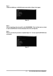
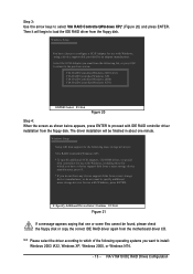
Then it will appear. You have copied the IDE RAID driver successfully. Step 3: Double-click MENU.exe. An MS-DOS prompt screen similar to Figure 16 will take about one minute to copy the IDE RAID driver from the motherboard driver CD to the floppy disk. Figure 17 - 11 - VIA VT6410 IDE RAID Drives Configuration Figure 16 Step 4: Insert an empty floppy disk and press H to exit when the procedure is completed (Figure 17). Step 5: Press 0 to select VIA 6410 RAID.
Then it will appear. You have copied the IDE RAID driver successfully. Step 3: Double-click MENU.exe. An MS-DOS prompt screen similar to Figure 16 will take about one minute to copy the IDE RAID driver from the motherboard driver CD to the floppy disk. Figure 17 - 11 - VIA VT6410 IDE RAID Drives Configuration Figure 16 Step 4: Insert an empty floppy disk and press H to exit when the procedure is completed (Figure 17). Step 5: Press 0 to select VIA 6410 RAID.
Manual
Page 12
... drives, or special disk controllers for use with Windows, press ENTER. Windows Setup Press F6 if you to specify the IDE RAID controller on your motherboard. After pressing the F6 key, there will be asked to install a 3rd party SCSI or RAID driver. Ác (5) Installing IDE RAID controller driver during OS... and press F6 as soon as you have chosen to manually specify an adapter. Then you need to select the IDE RAID controller on your motherboard.
... drives, or special disk controllers for use with Windows, press ENTER. Windows Setup Press F6 if you to specify the IDE RAID controller on your motherboard. After pressing the F6 key, there will be asked to install a 3rd party SCSI or RAID driver. Ác (5) Installing IDE RAID controller driver during OS... and press F6 as soon as you have chosen to manually specify an adapter. Then you need to select the IDE RAID controller on your motherboard.
Manual
Page 13
... finished in about one or some files cannot be found, please check the floppy disk or copy the correct IDE RAID driver again from the motherboard driver CD. Windows Setup You have any device support disks from a mass storage device manufacturer, or do not want to configure a SCSI Adapter for use...
... finished in about one or some files cannot be found, please check the floppy disk or copy the correct IDE RAID driver again from the motherboard driver CD. Windows Setup You have any device support disks from a mass storage device manufacturer, or do not want to configure a SCSI Adapter for use...
Manual
Page 1
GA-8I915G Duo Intel® Pentium® 4 LGA775 Processor Motherboard User's Manual Rev. 1303 12ME-8I915GDUO-1303
GA-8I915G Duo Intel® Pentium® 4 LGA775 Processor Motherboard User's Manual Rev. 1303 12ME-8I915GDUO-1303
Manual
Page 2
Motherboard GA-8I915G Duo Sep. 1, 2004 Motherboard GA-8I915G Duo Sep. 1, 2004
Motherboard GA-8I915G Duo Sep. 1, 2004 Motherboard GA-8I915G Duo Sep. 1, 2004
Manual
Page 4
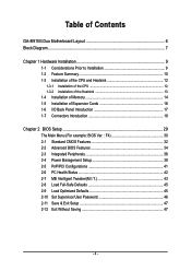
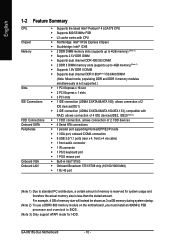
Table of Contents GA-8I915G Duo Motherboard Layout 6 Block Diagram ...7 Chapter 1 Hardware Installation 9 1-1 Considerations Prior to Installation 9 1-2 Feature Summary 10 1-3 Installation of the CPU and Heatsink 12 1-3-1 Installation of the CPU 12 1-3-2 ...
Table of Contents GA-8I915G Duo Motherboard Layout 6 Block Diagram ...7 Chapter 1 Hardware Installation 9 1-1 Considerations Prior to Installation 9 1-2 Feature Summary 10 1-3 Installation of the CPU and Heatsink 12 1-3-1 Installation of the CPU 12 1-3-2 ...
Manual
Page 6
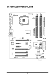
GA-8I915G Duo Motherboard Layout DDRII_2 DDRII_1 DDR1 DDR2 PWR_FAN KB_MS ATX_12V LGA775 ATX SPDIF_O SPDIF_I CPU_FAN VGA LPT IDE1 GA-8I915G Duo USB LAN2 USB AUDIO1 AUDIO2 CD_IN AZALIA_FP Broadcom 5751/5789 CODEC NB_FAN PCIE_1 PCIE_2 IT8712 COMA IR Intel 915G PCIE_16 BIOS BAT PCI1 PCI2 PCI3 SYS_FAN CLR_CMOS S_ATA3 ICH6 IDE2 S_ATA2 S_ATA1 S_ATA0 IDE3 VT6410 FDD F_USB2 F_PANEL F_USB1 PWR_LED - 6 -
GA-8I915G Duo Motherboard Layout DDRII_2 DDRII_1 DDR1 DDR2 PWR_FAN KB_MS ATX_12V LGA775 ATX SPDIF_O SPDIF_I CPU_FAN VGA LPT IDE1 GA-8I915G Duo USB LAN2 USB AUDIO1 AUDIO2 CD_IN AZALIA_FP Broadcom 5751/5789 CODEC NB_FAN PCIE_1 PCIE_2 IT8712 COMA IR Intel 915G PCIE_16 BIOS BAT PCI1 PCI2 PCI3 SYS_FAN CLR_CMOS S_ATA3 ICH6 IDE2 S_ATA2 S_ATA1 S_ATA0 IDE3 VT6410 FDD F_USB2 F_PANEL F_USB1 PWR_LED - 6 -
Manual
Page 7
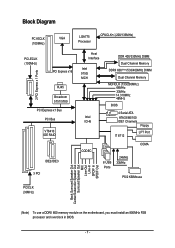
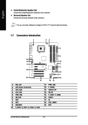
... Center/Subwoofer Speaker Out Surround Speaker Out MIC Line-Out Line-In SPDIF In SPDIF Out (Note) To use a DDRII 600 memory module on the motherboard, you must install an 800MHz FSB processor and overclock in BIOS. - 7 -
... Center/Subwoofer Speaker Out Surround Speaker Out MIC Line-Out Line-In SPDIF In SPDIF Out (Note) To use a DDRII 600 memory module on the motherboard, you must install an 800MHz FSB processor and overclock in BIOS. - 7 -
Manual
Page 9
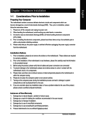
... components as well as a result of uncertified components. 5. To prevent damage to the motherboard, please do not allow screws to be an unofficial Gigabyte product. - 9 - Hardware Installation Please turn off before unplugging the power supply connector from the motherboard. Please verify that all cables and power connectors are uncertain about any installation steps...
... components as well as a result of uncertified components. 5. To prevent damage to the motherboard, please do not allow screws to be an unofficial Gigabyte product. - 9 - Hardware Installation Please turn off before unplugging the power supply connector from the motherboard. Please verify that all cables and power connectors are uncertain about any installation steps...
Manual
Page 10
... architecture, a certain amount of memory size will instead be shown as 3.xxGB memory during system startup. (Note 2) To use a DDRII 600 memory module on the motherboard, you must install an 800MHz FSB processor and overclock in BIOS. (Note 3) Only support ATAPI mode for system usage and therefore the actual memory size... channel DDR II 600(Note 2)/533/400 DIMM (Note: Mixed mode, populating DDR and DDR II memory modules simultaneously is less than the stated amount. GA-8I915G Duo Motherboard - 10 - For example, 4 GB of memory is reserved for HDD.
... architecture, a certain amount of memory size will instead be shown as 3.xxGB memory during system startup. (Note 2) To use a DDRII 600 memory module on the motherboard, you must install an 800MHz FSB processor and overclock in BIOS. (Note 3) Only support ATAPI mode for system usage and therefore the actual memory size... channel DDR II 600(Note 2)/533/400 DIMM (Note: Mixed mode, populating DDR and DDR II memory modules simultaneously is less than the stated amount. GA-8I915G Duo Motherboard - 10 - For example, 4 GB of memory is reserved for HDD.
Manual
Page 12
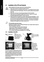
... HT Technology 1-3-1 Installation of the CPU. 3. Please set beyond the proper specifications, please do so according to the CPU during installation.) GA-8I915G Duo Motherboard - 12 - OS: An operation system that the motherboard supports the CPU. 2. Fig. 4 Once the CPU is installed on the CPU socket to set the frequency beyond hardware specifications since it...
... HT Technology 1-3-1 Installation of the CPU. 3. Please set beyond the proper specifications, please do so according to the CPU during installation.) GA-8I915G Duo Motherboard - 12 - OS: An operation system that the motherboard supports the CPU. 2. Fig. 4 Once the CPU is installed on the CPU socket to set the frequency beyond hardware specifications since it...
Manual
Page 13
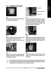
Fig. 6 Finally, please attach the power connector of motherboard after installing. Hardware Installation Fig. 2 (Turning the push pin along the direction of arrow is ...the user manual) Fig. 5 Please check the back of the heatsink to the pin hole on the motherboard.Pressing down the push pins diagonally. Fig. 4 Please make sure the push pins aim to the CPU fan header located... on the motherboard. English 1-3-2 Installation of the Heatsink Male Push Pin The top of Female Push Pin Female Push Pin Fig...
Fig. 6 Finally, please attach the power connector of motherboard after installing. Hardware Installation Fig. 2 (Turning the push pin along the direction of arrow is ...the user manual) Fig. 5 Please check the back of the heatsink to the pin hole on the motherboard.Pressing down the push pins diagonally. Fig. 4 Please make sure the push pins aim to the CPU fan header located... on the motherboard. English 1-3-2 Installation of the Heatsink Male Push Pin The top of Female Push Pin Female Push Pin Fig...
Manual
Page 14
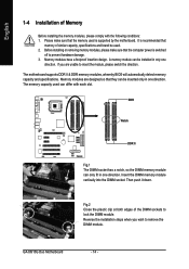
... DIMM sockets to insert the module, please switch the direction. It is switched off to remove the DIMM module. The motherboard supports DDR II & DDR memory modules, whereby BIOS will automatically detect memory capacity and specifications. Memory modules are unable to... and brand be installed in one direction. Please make sure that the computer power is recommended that the memory used . 2. GA-8I915G Duo Motherboard - 14 - English 1-4 Installation of Memory Before installing the memory modules, please comply with each slot. Reverse the installation steps...
... DIMM sockets to insert the module, please switch the direction. It is switched off to remove the DIMM module. The motherboard supports DDR II & DDR memory modules, whereby BIOS will automatically detect memory capacity and specifications. Memory modules are unable to... and brand be installed in one direction. Please make sure that the computer power is recommended that the memory used . 2. GA-8I915G Duo Motherboard - 14 - English 1-4 Installation of Memory Before installing the memory modules, please comply with each slot. Reverse the installation steps...
Manual
Page 16
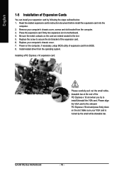
...PCI Express x 16 slot and press firmly down on the slot .Make sure your computer's chassis cover, screws and slot bracket from BIOS. 8. GA-8I915G Duo Motherboard - 16 - Be sure the metal contacts on the computer, if necessary, setup BIOS utility of the expansion card. 6. English 1-5 Installation of... following the steps outlined below: 1. Press the expansion card firmly into the computer. 2. Power on the card are indeed seated in motherboard. 4. Please align the VGA card to secure the slot bracket of expansion card from the computer. 3. Install related driver from the ...
...PCI Express x 16 slot and press firmly down on the slot .Make sure your computer's chassis cover, screws and slot bracket from BIOS. 8. GA-8I915G Duo Motherboard - 16 - Be sure the metal contacts on the computer, if necessary, setup BIOS utility of the expansion card. 6. English 1-5 Installation of... following the steps outlined below: 1. Press the expansion card firmly into the computer. 2. Power on the card are indeed seated in motherboard. 4. Please align the VGA card to secure the slot bracket of expansion card from the computer. 3. Install related driver from the ...
Manual
Page 18
.../IDE3 10) S_ATA0 / S_ATA1 / S_ATA2 / S_ATA3 11) PWR_LED 12) F_PANEL 13) AZALIA_FP 14) CD_IN 15) F_USB1 / F_USB2 16) COM A 17) IR 18) CLR_CMOS 19) BAT GA-8I915G Duo Motherboard - 18 - You can use audio software to this connector. English Center/Subwoofer Speaker Out Connect the Center/Subwoofer channels to this connector.
.../IDE3 10) S_ATA0 / S_ATA1 / S_ATA2 / S_ATA3 11) PWR_LED 12) F_PANEL 13) AZALIA_FP 14) CD_IN 15) F_USB1 / F_USB2 16) COM A 17) IR 18) CLR_CMOS 19) BAT GA-8I915G Duo Motherboard - 18 - You can use audio software to this connector. English Center/Subwoofer Speaker Out Connect the Center/Subwoofer channels to this connector.
Manual
Page 19
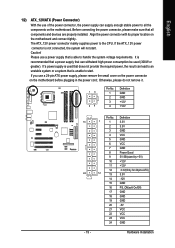
... ATX_12V power connector is able to all components and devices are properly installed. It is recommended that a power supply that all the components on the motherboard. If a power supply is unable to the CPU. Pin No. Otherwise, please do not remove it. 13 24 Pin No. 1 2 3 4 Definition GND GND +12V... GND 19 GND 20 -5V 21 VCC 22 VCC 23 VCC 24 GND Hardware Installation Align the power connector with its proper location on the motherboard before plugging in the power cord ; If you use a 24-pin ATX power supply, please remove the small cover on the power connector...
... ATX_12V power connector is able to all components and devices are properly installed. It is recommended that a power supply that all the components on the motherboard. If a power supply is unable to the CPU. Pin No. Otherwise, please do not remove it. 13 24 Pin No. 1 2 3 4 Definition GND GND +12V... GND 19 GND 20 -5V 21 VCC 22 VCC 23 VCC 24 GND Hardware Installation Align the power connector with its proper location on the motherboard before plugging in the power cord ; If you use a 24-pin ATX power supply, please remove the small cover on the power connector...
Manual
Page 20
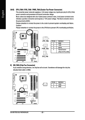
The black connector wire is GND) Pin No. Definition 1 1 +12V 2 GND GA-8I915G Duo Motherboard - 20 - Most coolers are designed with color-coded power connector wires. Caution! Sometimes will not work. English 3/4/5) CPU_FAN / SYS_FAN / PWR_FAN (Cooler Fan Power Connector) The ...
The black connector wire is GND) Pin No. Definition 1 1 +12V 2 GND GA-8I915G Duo Motherboard - 20 - Most coolers are designed with color-coded power connector wires. Caution! Sometimes will not work. English 3/4/5) CPU_FAN / SYS_FAN / PWR_FAN (Cooler Fan Power Connector) The ...

Manual
Page 22
It will blink when the system enters suspend mode. Definition 1 GND 7 1 2 TXP 3 TXN 4 GND 5 RXN 6 RXP 7 GND 11) PWR_LED PWR_LED is on/off. Pin No. Pin No. Definition 1 1 MPD+ 2 MPD- 3 MPD- English 10) S_ATA0/S_ATA1/S_ATA2/S_ATA3 (Serial ATA Connector) Serial ATA can provide 150MB/s transfer rate. Please refer to the BIOS setting for the Serial ATA and install the proper driver in order to indicate whether the system is connect with the system power indicator to work properly. GA-8I915G Duo Motherboard - 22 -
It will blink when the system enters suspend mode. Definition 1 GND 7 1 2 TXP 3 TXN 4 GND 5 RXN 6 RXP 7 GND 11) PWR_LED PWR_LED is on/off. Pin No. Pin No. Definition 1 1 MPD+ 2 MPD- 3 MPD- English 10) S_ATA0/S_ATA1/S_ATA2/S_ATA3 (Serial ATA Connector) Serial ATA can provide 150MB/s transfer rate. Please refer to the BIOS setting for the Serial ATA and install the proper driver in order to indicate whether the system is connect with the system power indicator to work properly. GA-8I915G Duo Motherboard - 22 -


