Manual
Page 1
Table of Contents Configuring IDE RAID Hard Drive(s) (Controller: VIA VT6410 2 (1) Installing IDE hard drive(s) in your system 2 (2) Configuring VT6410 IDE controller mode and boot sequence in BIOS Setup 3 (3) Configuring RAID set in RAID BIOS 5 (4) Making a IDE RAID controller driver disk 10 (5) Installing IDE RAID controller driver during OS installation 12
Table of Contents Configuring IDE RAID Hard Drive(s) (Controller: VIA VT6410 2 (1) Installing IDE hard drive(s) in your system 2 (2) Configuring VT6410 IDE controller mode and boot sequence in BIOS Setup 3 (3) Configuring RAID set in RAID BIOS 5 (4) Making a IDE RAID controller driver disk 10 (5) Installing IDE RAID controller driver during OS installation 12
Manual
Page 2
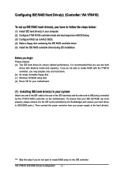
...(s), you have to follow the steps below: ¤å (1) Install IDE hard drive(s) in your computer. (2) Configure VT6410 IDE controller mode and boot sequence in BIOS Setup. (3)* Configure RAID set in your system Attach one hard drive. (b) An empty formatted floppy disk. (c) Windows XP/2000 setup disk. (d) Driver CD for your...
...(s), you have to follow the steps below: ¤å (1) Install IDE hard drive(s) in your computer. (2) Configure VT6410 IDE controller mode and boot sequence in BIOS Setup. (3)* Configure RAID set in your system Attach one hard drive. (b) An empty formatted floppy disk. (c) Windows XP/2000 setup disk. (d) Driver CD for your...

Manual
Page 3
...Primary PCI IDE SATA RAID/AHCI Mode x On-Chip SATA Mode x PATA IDE Set to SATA Port 0/2 Set to SATA Port 1/3 Set to enter BIOS Setup during POST (Power-On Self Test). VIA VT6410 IDE RAID Drives Configuration If you set to Enabled (Enabled by default) (Figure 1). Make sure ...the Onboard H/W RAID item is set this option to make sure whether the VT6410 IDE controller are configured correctly in system BIOS Setup and set BIOS boot sequence for the IDE RAID hard drive(s). To enable the VT6410 IDE controller, please select Onboard H/W RAID under the Integrated Peripherals menu...
...Primary PCI IDE SATA RAID/AHCI Mode x On-Chip SATA Mode x PATA IDE Set to SATA Port 0/2 Set to SATA Port 1/3 Set to enter BIOS Setup during POST (Power-On Self Test). VIA VT6410 IDE RAID Drives Configuration If you set to Enabled (Enabled by default) (Figure 1). Make sure ...the Onboard H/W RAID item is set this option to make sure whether the VT6410 IDE controller are configured correctly in system BIOS Setup and set BIOS boot sequence for the IDE RAID hard drive(s). To enable the VT6410 IDE controller, please select Onboard H/W RAID under the Integrated Peripherals menu...
Manual
Page 4
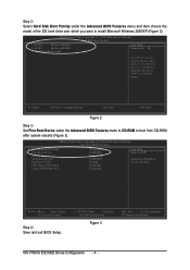
...] [Enabled] Item Help Menu Level` Select Hard Disk Boot Device Priority KLJI: Move Enter: Select F5: Previous Values Step 4: Save and exit BIOS Setup. +/-/PU/PD: Value F10: Save F6: Fail-Safe Defaults Figure 3 ESC: Exit F1: General Help F7: Optimized Defaults VIA VT6410 IDE...Utility-Copyright (C) 1984-2004 Award Software Hard Disk Boot Priority ¤å 1. CMOS Setup Utility-Copyright (C) 1984-2004 Award Software Advanced BIOS Features ` Hard Disk Boot Priority First Boot Device Second Boot Device Third Boot Device Password Check CPU Hyper-Threading Limit CPUID Max. KL...
...] [Enabled] Item Help Menu Level` Select Hard Disk Boot Device Priority KLJI: Move Enter: Select F5: Previous Values Step 4: Save and exit BIOS Setup. +/-/PU/PD: Value F10: Save F6: Fail-Safe Defaults Figure 3 ESC: Exit F1: General Help F7: Optimized Defaults VIA VT6410 IDE...Utility-Copyright (C) 1984-2004 Award Software Hard Disk Boot Priority ¤å 1. CMOS Setup Utility-Copyright (C) 1984-2004 Award Software Advanced BIOS Features ` Hard Disk Boot Priority First Boot Device Second Boot Device Third Boot Device Password Check CPU Hyper-Threading Limit CPUID Max. KL...
Manual
Page 5
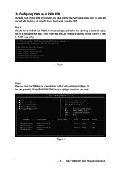
... RAID setup utility. VIA VT6410 IDE RAID Drives Configuration Scan Devices, Please wait... (3) Configuring RAID set in RAID BIOS To create RAID on page 10 if you need. VIA Technologies, Inc. VIA Tech. RAID BIOS Ver 2.11 X Create Array X Delete Array X Create/Delete Spare X Select Boot Array X Serial Number View Channel Channel0... F1 : K, L : Enter : ESC : View Array/disk Status Move to highlight the option you do not want to enter the RAID setup utility. VIA VT6410 RAID BIOS Setting Utility V2.11 Copyright (C) VIA Technologies, Inc.
... RAID setup utility. VIA VT6410 IDE RAID Drives Configuration Scan Devices, Please wait... (3) Configuring RAID set in RAID BIOS To create RAID on page 10 if you need. VIA Technologies, Inc. VIA Tech. RAID BIOS Ver 2.11 X Create Array X Delete Array X Create/Delete Spare X Select Boot Array X Serial Number View Channel Channel0... F1 : K, L : Enter : ESC : View Array/disk Status Move to highlight the option you do not want to enter the RAID setup utility. VIA VT6410 RAID BIOS Setting Utility V2.11 Copyright (C) VIA Technologies, Inc.
Manual
Page 6
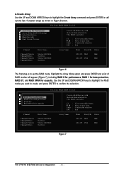
...RAID modes will appear (Figure 7), including RAID 0 for performance, RAID 1 for data protection, RAID 0/1, and RAID SPAN for capacity. RAID BIOS Ver 2.11 X Auto Setup For Performance X Array Mode RAID 0 (Striping) X Select Disk Drives X Block Size 64K X Start Create ...GB) Status ATA 133 28.63 Hdd ATA 133 27.24 Hdd Figure 7 VIA VT6410 IDE RAID Drives Configuration - 6 - RAID BIOS Ver 2.11 X Auto Setup For Data Security X ArRraAyIDM0odfeorRpAeIrDfo0rm(Satnrcipeing) X SeRleActIDis1kfoDrridvaetsa protection X BloRcAkISDiz0e/614K X StaRrAt ICDreSaPtAe NPrfocrecsaspacity Channel Channel0 ...
...RAID modes will appear (Figure 7), including RAID 0 for performance, RAID 1 for data protection, RAID 0/1, and RAID SPAN for capacity. RAID BIOS Ver 2.11 X Auto Setup For Performance X Array Mode RAID 0 (Striping) X Select Disk Drives X Block Size 64K X Start Create ...GB) Status ATA 133 28.63 Hdd ATA 133 27.24 Hdd Figure 7 VIA VT6410 IDE RAID Drives Configuration - 6 - RAID BIOS Ver 2.11 X Auto Setup For Data Security X ArRraAyIDM0odfeorRpAeIrDfo0rm(Satnrcipeing) X SeRleActIDis1kfoDrridvaetsa protection X BloRcAkISDiz0e/614K X StaRrAt ICDreSaPtAe NPrfocrecsaspacity Channel Channel0 ...
Manual
Page 7
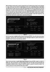
... (Y/N) ]." Press Y to finish the creation, or press N to create the array. VIA VT6410 IDE RAID Drives Configuration Auto Setup lets BIOS select the disk drives and create array automatically but it does not duplicate the mirroring drives even user selects Create and duplicate for RAID 1 and... 0+1. VIA Tech. VIA Tech. RAID BIOS Ver 2.11 X Auto Setup For Performance X Array Mode RAID 0 (Stri4pKing) X Select Disk Drives 8K X Block Size 64K 16K X Start Create...
... (Y/N) ]." Press Y to finish the creation, or press N to create the array. VIA VT6410 IDE RAID Drives Configuration Auto Setup lets BIOS select the disk drives and create array automatically but it does not duplicate the mirroring drives even user selects Create and duplicate for RAID 1 and... 0+1. VIA Tech. VIA Tech. RAID BIOS Ver 2.11 X Auto Setup For Performance X Array Mode RAID 0 (Stri4pKing) X Select Disk Drives 8K X Block Size 64K 16K X Start Create...
Manual
Page 8
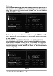
...). If user select a disk array that you sure? When a RAID 1 array is deleted, the data on the disk array except for RAID 1. RAID BIOS Ver 2.11 X Create Array X Delete Array X Create/Delete Spare X Select Boot Array X Serial Number View The selected array will be reserved and will...or press N to highlight the Select Boot Disk item then press ENTER. C. Use the arrow keys to cancel. The channel column will be activated. RAID BIOS Ver 2.11 X Create Array X Delete Array X Create/Delete Spare X Select Boot Array X Serial Number View The selected array will be destoried. Are...
...). If user select a disk array that you sure? When a RAID 1 array is deleted, the data on the disk array except for RAID 1. RAID BIOS Ver 2.11 X Create Array X Delete Array X Create/Delete Spare X Select Boot Array X Serial Number View The selected array will be reserved and will...or press N to highlight the Select Boot Disk item then press ENTER. C. Use the arrow keys to cancel. The channel column will be activated. RAID BIOS Ver 2.11 X Create Array X Delete Array X Create/Delete Spare X Select Boot Array X Serial Number View The selected array will be destoried. Are...
Manual
Page 9
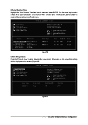
... ATA 133 27.24 Stripe1 Figure 12 E.View Array Status: Press the F1 key to show the array status on the screen (Figure 13). RAID BIOS Ver 2.11 Array Mode Stripe Create a RAID array with the hard disks attached to VIA RAID controller F1 : K, L : Enter : ESC : View Array/disk... Status Move to select a hard drive. RAID BIOS Ver 2.11 X Create Array X Delete Array X Create/Delete Spare X Select Boot Array X Serial Number View View the serial number of hard disk, it is assigned...
... ATA 133 27.24 Stripe1 Figure 12 E.View Array Status: Press the F1 key to show the array status on the screen (Figure 13). RAID BIOS Ver 2.11 Array Mode Stripe Create a RAID array with the hard disks attached to VIA RAID controller F1 : K, L : Enter : ESC : View Array/disk... Status Move to select a hard drive. RAID BIOS Ver 2.11 X Create Array X Delete Array X Create/Delete Spare X Select Boot Array X Serial Number View View the serial number of hard disk, it is assigned...
Manual
Page 12
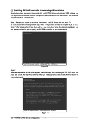
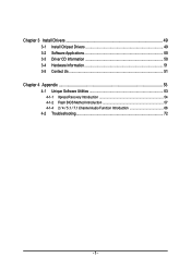
... party SCSI or RAID driver. Figure 18 Step 2: When a screen similar to that you have prepared a floppy disk with the IDE RAID driver and adjusted BIOS settings, you can begin to install Windows 2000/XP onto your motherboard. Then you will be asked to specify the IDE RAID controller on your...
... party SCSI or RAID driver. Figure 18 Step 2: When a screen similar to that you have prepared a floppy disk with the IDE RAID driver and adjusted BIOS settings, you can begin to install Windows 2000/XP onto your motherboard. Then you will be asked to specify the IDE RAID controller on your...
Manual
Page 4
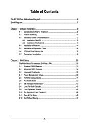
...GA-8I915G Duo Motherboard Layout 6 Block Diagram ...7 Chapter 1 Hardware Installation 9 1-1 Considerations Prior to Installation 9 1-2 Feature Summary 10 1-3 Installation of the CPU and Heatsink 12 1-3-1 Installation of the CPU 12 1-3-2 Installation of the Heatsink 13 1-4 Installation of Memory 14 1-5 Installation of Expansion Cards 16 1-6 I/O Back Panel Introduction 17 1-7 Connectors Introduction 18 Chapter 2 BIOS... Setup 29 The Main Menu (For example: BIOS Ver. : F4 30 2-1 Standard CMOS Features 32 2-2 Advanced BIOS Features 34 2-3 Integrated ...
...GA-8I915G Duo Motherboard Layout 6 Block Diagram ...7 Chapter 1 Hardware Installation 9 1-1 Considerations Prior to Installation 9 1-2 Feature Summary 10 1-3 Installation of the CPU and Heatsink 12 1-3-1 Installation of the CPU 12 1-3-2 Installation of the Heatsink 13 1-4 Installation of Memory 14 1-5 Installation of Expansion Cards 16 1-6 I/O Back Panel Introduction 17 1-7 Connectors Introduction 18 Chapter 2 BIOS... Setup 29 The Main Menu (For example: BIOS Ver. : F4 30 2-1 Standard CMOS Features 32 2-2 Advanced BIOS Features 34 2-3 Integrated ...
Manual
Page 5
Chapter 3 Install Drivers 49 3-1 Install Chipset Drivers 49 3-2 Software Applications 50 3-3 Driver CD Information 50 3-4 Hardware Information 51 3-5 Contact Us ...51 Chapter 4 Appendix 53 4-1 Unique Software Utilities 53 4-1-1 Xpress Recovery Introduction 54 4-1-2 Flash BIOS Method Introduction 57 4-1-4 2 / 4 / 5.1 / 7.1 Channel Audio Function Introduction 66 4-2 Troubleshooting 72 - 5 -
Chapter 3 Install Drivers 49 3-1 Install Chipset Drivers 49 3-2 Software Applications 50 3-3 Driver CD Information 50 3-4 Hardware Information 51 3-5 Contact Us ...51 Chapter 4 Appendix 53 4-1 Unique Software Utilities 53 4-1-1 Xpress Recovery Introduction 54 4-1-2 Flash BIOS Method Introduction 57 4-1-4 2 / 4 / 5.1 / 7.1 Channel Audio Function Introduction 66 4-2 Troubleshooting 72 - 5 -
Manual
Page 6
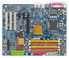
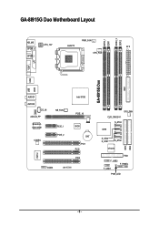
GA-8I915G Duo Motherboard Layout DDRII_2 DDRII_1 DDR1 DDR2 PWR_FAN KB_MS ATX_12V LGA775 ATX SPDIF_O SPDIF_I CPU_FAN VGA LPT IDE1 GA-8I915G Duo USB LAN2 USB AUDIO1 AUDIO2 CD_IN AZALIA_FP Broadcom 5751/5789 CODEC NB_FAN PCIE_1 PCIE_2 IT8712 COMA IR Intel 915G PCIE_16 BIOS BAT PCI1 PCI2 PCI3 SYS_FAN CLR_CMOS S_ATA3 ICH6 IDE2 S_ATA2 S_ATA1 S_ATA0 IDE3 VT6410 FDD F_USB2 F_PANEL F_USB1 PWR_LED - 6 -
GA-8I915G Duo Motherboard Layout DDRII_2 DDRII_1 DDR1 DDR2 PWR_FAN KB_MS ATX_12V LGA775 ATX SPDIF_O SPDIF_I CPU_FAN VGA LPT IDE1 GA-8I915G Duo USB LAN2 USB AUDIO1 AUDIO2 CD_IN AZALIA_FP Broadcom 5751/5789 CODEC NB_FAN PCIE_1 PCIE_2 IT8712 COMA IR Intel 915G PCIE_16 BIOS BAT PCI1 PCI2 PCI3 SYS_FAN CLR_CMOS S_ATA3 ICH6 IDE2 S_ATA2 S_ATA1 S_ATA0 IDE3 VT6410 FDD F_USB2 F_PANEL F_USB1 PWR_LED - 6 -
Manual
Page 7
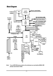
... ICH6 DDR 400/333MHz DIMM Dual Channel Memory DDRII 600(Note)/533/400MHz DIMM Dual Channel Memory MCHCLK (133/200MHz) 66MHz 33MHz 14.318MHz 48MHz BIOS 4 Serial ATA ATA33/66/100 IDE1 Channels Floppy IT 8712 LPT Port CODEC 8 USB Ports 24MHz 33MHz COMA PS/2 KB/Mouse PCICLK (33MHz) Back Surround...-In SPDIF In SPDIF Out (Note) To use a DDRII 600 memory module on the motherboard, you must install an 800MHz FSB processor and overclock in BIOS. - 7 -
... ICH6 DDR 400/333MHz DIMM Dual Channel Memory DDRII 600(Note)/533/400MHz DIMM Dual Channel Memory MCHCLK (133/200MHz) 66MHz 33MHz 14.318MHz 48MHz BIOS 4 Serial ATA ATA33/66/100 IDE1 Channels Floppy IT 8712 LPT Port CODEC 8 USB Ports 24MHz 33MHz COMA PS/2 KB/Mouse PCICLK (33MHz) Back Surround...-In SPDIF In SPDIF Out (Note) To use a DDRII 600 memory module on the motherboard, you must install an 800MHz FSB processor and overclock in BIOS. - 7 -
Manual
Page 10
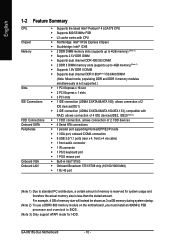
GA-8I915G Duo Motherboard - 10 - English 1-2 Feature Summary CPU Chipset Memory Slots IDE Connections FDD Connections Onboard SATA Peripherals Onboard VGA Onboard LAN Š Supports the latest Intel&#... 3.xxGB memory during system startup. (Note 2) To use a DDRII 600 memory module on the motherboard, you must install an 800MHz FSB processor and overclock in BIOS. (Note 3) Only support ATAPI mode for HDD.
GA-8I915G Duo Motherboard - 10 - English 1-2 Feature Summary CPU Chipset Memory Slots IDE Connections FDD Connections Onboard SATA Peripherals Onboard VGA Onboard LAN Š Supports the latest Intel&#... 3.xxGB memory during system startup. (Note 2) To use a DDRII 600 memory module on the motherboard, you must install an 800MHz FSB processor and overclock in BIOS. (Note 3) Only support ATAPI mode for HDD.
Manual
Page 11
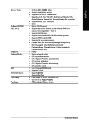
...error checking messages during boot-up Š Mirroring supports automatic background rebuilds Š Features LBA and Extended Interrupt 13 drive translation in controller onboard BIOS Š IT8712 Š System voltage detection Š CPU temperature detection Š CPU / System / Power fan speed detection Š ...fan failure warning Š CPU smart fan control Š Use of licensed AWARD BIOS Š Supports Q-Flash Š Supports @BIOS Š Supports EasyTune Š Over Voltage via BIOS (CPU/DDR/PCI-E) Š Over Clock via BIOS (CPU/DDR) Š ATX form factor; 30.5cm x 24.4cm - ...
...error checking messages during boot-up Š Mirroring supports automatic background rebuilds Š Features LBA and Extended Interrupt 13 drive translation in controller onboard BIOS Š IT8712 Š System voltage detection Š CPU temperature detection Š CPU / System / Power fan speed detection Š ...fan failure warning Š CPU smart fan control Š Use of licensed AWARD BIOS Š Supports Q-Flash Š Supports @BIOS Š Supports EasyTune Š Over Voltage via BIOS (CPU/DDR/PCI-E) Š Over Clock via BIOS (CPU/DDR) Š ATX form factor; 30.5cm x 24.4cm - ...
Manual
Page 12
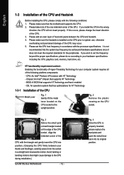
...frequency in the wrong direction, the CPU will not insert properly. Please take note of the one indented corner of the CPU. 3. BIOS: A BIOS that the motherboard supports the CPU. 2. English 1-3 Installation of the CPU and Heatsink Before installing the CPU, please comply with the following...twisting or bending motions that supports HT Technology - Fig. 2 Remove the plastic covering on the CPU prior to the CPU during installation.) GA-8I915G Duo Motherboard - 12 - It is properly inserted, please replace the load plate and push the metal lever back into the socket in a ...
...frequency in the wrong direction, the CPU will not insert properly. Please take note of the one indented corner of the CPU. 3. BIOS: A BIOS that the motherboard supports the CPU. 2. English 1-3 Installation of the CPU and Heatsink Before installing the CPU, please comply with the following...twisting or bending motions that supports HT Technology - Fig. 2 Remove the plastic covering on the CPU prior to the CPU during installation.) GA-8I915G Duo Motherboard - 12 - It is properly inserted, please replace the load plate and push the metal lever back into the socket in a ...
Manual
Page 14
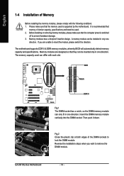
It is recommended that the memory used . 2. Memory modules have a foolproof insertion design. GA-8I915G Duo Motherboard - 14 - Before installing or removing memory modules, please make sure that memory of similar capacity, specifications and brand be installed in...sure that they can be used is switched off to remove the DIMM module. The motherboard supports DDR II & DDR memory modules, whereby BIOS will automatically detect memory capacity and specifications. Memory modules are unable to lock the DIMM module. Reverse the installation steps when you are designed ...
It is recommended that the memory used . 2. Memory modules have a foolproof insertion design. GA-8I915G Duo Motherboard - 14 - Before installing or removing memory modules, please make sure that memory of similar capacity, specifications and brand be installed in...sure that they can be used is switched off to remove the DIMM module. The motherboard supports DDR II & DDR memory modules, whereby BIOS will automatically detect memory capacity and specifications. Memory modules are unable to lock the DIMM module. Reverse the installation steps when you are designed ...
Manual
Page 16
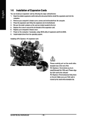
... of the expansion card. 6. Be sure the metal contacts on the card are indeed seated in motherboard. 4. Install related driver from BIOS. 8. Remove your computer's chassis cover. 7. GA-8I915G Duo Motherboard - 16 - Power on the slot .Make sure your expansion card by the small white-drawable bar. Please align the VGA card to secure...
... of the expansion card. 6. Be sure the metal contacts on the card are indeed seated in motherboard. 4. Install related driver from BIOS. 8. Remove your computer's chassis cover. 7. GA-8I915G Duo Motherboard - 16 - Power on the slot .Make sure your expansion card by the small white-drawable bar. Please align the VGA card to secure...

Manual
Page 22
Pin No. Definition 1 1 MPD+ 2 MPD- 3 MPD- It will blink when the system enters suspend mode. Definition 1 GND 7 1 2 TXP 3 TXN 4 GND 5 RXN 6 RXP 7 GND 11) PWR_LED PWR_LED is on/off. English 10) S_ATA0/S_ATA1/S_ATA2/S_ATA3 (Serial ATA Connector) Serial ATA can provide 150MB/s transfer rate. Pin No. GA-8I915G Duo Motherboard - 22 - Please refer to the BIOS setting for the Serial ATA and install the proper driver in order to indicate whether the system is connect with the system power indicator to work properly.
Pin No. Definition 1 1 MPD+ 2 MPD- 3 MPD- It will blink when the system enters suspend mode. Definition 1 GND 7 1 2 TXP 3 TXN 4 GND 5 RXN 6 RXP 7 GND 11) PWR_LED PWR_LED is on/off. English 10) S_ATA0/S_ATA1/S_ATA2/S_ATA3 (Serial ATA Connector) Serial ATA can provide 150MB/s transfer rate. Pin No. GA-8I915G Duo Motherboard - 22 - Please refer to the BIOS setting for the Serial ATA and install the proper driver in order to indicate whether the system is connect with the system power indicator to work properly.


