
Owner's Manual
Page 4
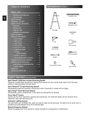
.... The light turns on when door is activated and automatically turns off 4.5 minutes later. Manual Emergency Release Allows the garage door to be opened or closed manually... stops and reverses a closing door within 30 seconds. TABLE OF CONTENTS SECTION PAGE PRE-INSTALLATION CHECK LIST 2-3 4 TOOLS REQUIRED 4 SAFETY FEATURES 4 OPERATIONAL FEATURES 5 PARTS LISTS AND ILLUSTRATIONS 5-8 POWER ... Step ladder Adjustable wrench Pencil Drill 5/ 32" Drill Bit Ratchet Wire strippers Phillips screwdriver 7/16" and 9/16" Sockets Tape measure SAFETY FEATURES (varies by model) Safe-T-Beam...
.... The light turns on when door is activated and automatically turns off 4.5 minutes later. Manual Emergency Release Allows the garage door to be opened or closed manually... stops and reverses a closing door within 30 seconds. TABLE OF CONTENTS SECTION PAGE PRE-INSTALLATION CHECK LIST 2-3 4 TOOLS REQUIRED 4 SAFETY FEATURES 4 OPERATIONAL FEATURES 5 PARTS LISTS AND ILLUSTRATIONS 5-8 POWER ... Step ladder Adjustable wrench Pencil Drill 5/ 32" Drill Bit Ratchet Wire strippers Phillips screwdriver 7/16" and 9/16" Sockets Tape measure SAFETY FEATURES (varies by model) Safe-T-Beam...
Owner's Manual
Page 5
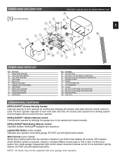
.... Independent light control allows convenient manual control of door operator by allowing the garage door to find in dark. INTELLICODE® Multi-Button Remote Control Operates multiple Intellicode® equipped door operators. An access code copied from a working system...GENIECOMPANY.COM 41 F R 5 G P 48 A 42 K L 45 39 M H 4 J N POWER HEAD PARTS LIST Item Part Name 1 Power Head Assembly A Cover (By Series/Model) B Front Plate Assembly C Light Socket D Motor Parts E Receiver Assembly F Capacitor (By Series/Model) G Opto Wheel H Opto-Luctor Assembly J Sequencer Assembly K Circuit ...
.... Independent light control allows convenient manual control of door operator by allowing the garage door to find in dark. INTELLICODE® Multi-Button Remote Control Operates multiple Intellicode® equipped door operators. An access code copied from a working system...GENIECOMPANY.COM 41 F R 5 G P 48 A 42 K L 45 39 M H 4 J N POWER HEAD PARTS LIST Item Part Name 1 Power Head Assembly A Cover (By Series/Model) B Front Plate Assembly C Light Socket D Motor Parts E Receiver Assembly F Capacitor (By Series/Model) G Opto Wheel H Opto-Luctor Assembly J Sequencer Assembly K Circuit ...
Owner's Manual
Page 9
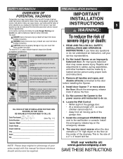
...Locate the Wall Control: • Within sight of the garage door. • At a minimum height of 5', so small children cannot reach it. • Away from 1. Install the emergency release tag on an improperly balanced door. This is moving parts of to follow , the words Danger, Warning, and Caution... or injury can result from failure To reduce the risk of the garage door. 7. NOTE: Please keep original or photocopy of your sales receipt with this section and those that follow instructions. Since moving parts. The word NOTE is used to follow instructions. Do Not allow ...
...Locate the Wall Control: • Within sight of the garage door. • At a minimum height of 5', so small children cannot reach it. • Away from 1. Install the emergency release tag on an improperly balanced door. This is moving parts of to follow , the words Danger, Warning, and Caution... or injury can result from failure To reduce the risk of the garage door. 7. NOTE: Please keep original or photocopy of your sales receipt with this section and those that follow instructions. Since moving parts. The word NOTE is used to follow instructions. Do Not allow ...

Owner's Manual
Page 16
... highest point of travel. • While raising garage door manually, watch top edge of door to see where it onto the rail. (A stool, chair, table or any object that can be used to "highest point of door Fig. 2-4 This is called "highest point of travel . With door held partly open (at centerline on centerline. Fig. 2-3. •...
... highest point of travel. • While raising garage door manually, watch top edge of door to see where it onto the rail. (A stool, chair, table or any object that can be used to "highest point of door Fig. 2-4 This is called "highest point of travel . With door held partly open (at centerline on centerline. Fig. 2-3. •...
Owner's Manual
Page 17
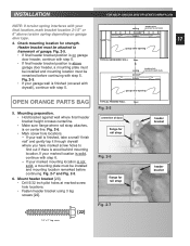
... 5. Fig. 2-5. garage door opening OPEN ORANGE PARTS BAG TYPICAL FINISHED WALL floor Fig. 2-5 5. header • If your garage wall is wood behind mounting location. Fig. 2-7 and Fig. 2-5. 6. Fig. 2-5. garage door opening • If final header bracket position is on garage door header, continue with your...screws [22]. If your final location, mark bracket location 2-1/2" or ceiling wooden plate fastened to wall studs 6" above garage door header, a mounting plate must be installed and mounting location must be CL ceiling wooden plate fastened to wall studs remarked ...
... 5. Fig. 2-5. garage door opening OPEN ORANGE PARTS BAG TYPICAL FINISHED WALL floor Fig. 2-5 5. header • If your garage wall is wood behind mounting location. Fig. 2-7 and Fig. 2-5. 6. Fig. 2-5. garage door opening • If final header bracket position is on garage door header, continue with your...screws [22]. If your final location, mark bracket location 2-1/2" or ceiling wooden plate fastened to wall studs 6" above garage door header, a mounting plate must be installed and mounting location must be CL ceiling wooden plate fastened to wall studs remarked ...
Owner's Manual
Page 22
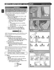
... brackets can cut wires. [30] Insulated staple Fig. 3-1 mark center of garage receives most direct sunlight Fig. 3-4, and place Red LED here whenever possible Fig. 3-4. • For multiple doors. - If not: a. OPEN RED PARTS BAG 3. Staples which side of bracket Fig. 3-2 SUN Fig. 3-3 tongue RED... LED GREEN LED GREEN LED RED RED LED LED GREEN LED ONE DOOR GARAGE TWO DOOR GARAGE GREEN LED RED RED LED LED GREEN GREEN...
... brackets can cut wires. [30] Insulated staple Fig. 3-1 mark center of garage receives most direct sunlight Fig. 3-4, and place Red LED here whenever possible Fig. 3-4. • For multiple doors. - If not: a. OPEN RED PARTS BAG 3. Staples which side of bracket Fig. 3-2 SUN Fig. 3-3 tongue RED... LED GREEN LED GREEN LED RED RED LED LED GREEN LED ONE DOOR GARAGE TWO DOOR GARAGE GREEN LED RED RED LED LED GREEN GREEN...
Owner's Manual
Page 25
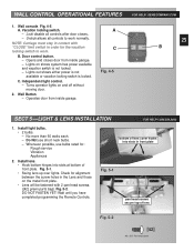
...OPERATIONAL FEATURES 1. NOTE: Carriage must stay in contact with 2 pan head screws. ([42] green parts bag). B. Door control button. - GENIECOMPANY.COM 25 B SECT 5 -LIGHT & LENS INSTALLATION FOR HELP-1.800.354.... Install lens. • Hook bottom hinges into slots in the Lens and those on and off without moving door. 2. Turns operator lights on the metal front plate. • Lens will be fastened with "CLOSE" limit... controls to work normally. Opens and closes door from inside garage. - Operates door from inside garage. Install light bulbs. • 2 bulbs. -
...OPERATIONAL FEATURES 1. NOTE: Carriage must stay in contact with 2 pan head screws. ([42] green parts bag). B. Door control button. - GENIECOMPANY.COM 25 B SECT 5 -LIGHT & LENS INSTALLATION FOR HELP-1.800.354.... Install lens. • Hook bottom hinges into slots in the Lens and those on and off without moving door. 2. Turns operator lights on the metal front plate. • Lens will be fastened with "CLOSE" limit... controls to work normally. Opens and closes door from inside garage. - Operates door from inside garage. Install light bulbs. • 2 bulbs. -
Owner's Manual
Page 27
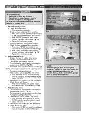
... slightly (about 1/16 turn ). • Repeat until lever is between door and carriage. - Be sure and set force adjustments at minimum required to the obstruction, garage door or garage door operator. Set limit switch position. • Check door fully closed . - SECT 7-SETTINGS (FORCE & LIMITS) FOR HELP-1.800...head-find adjusting screw marked "CLOSE." Fig. 7-1. - If not, increase opening force. • Engage Carriage by moving parts. Fig. 7-2. • Turn screw gently counterclockwise until lever is fully open . If not, move "CLOSE" limit switch toward carriage until...
... slightly (about 1/16 turn ). • Repeat until lever is between door and carriage. - Be sure and set force adjustments at minimum required to the obstruction, garage door or garage door operator. Set limit switch position. • Check door fully closed . - SECT 7-SETTINGS (FORCE & LIMITS) FOR HELP-1.800...head-find adjusting screw marked "CLOSE." Fig. 7-1. - If not, increase opening force. • Engage Carriage by moving parts. Fig. 7-2. • Turn screw gently counterclockwise until lever is fully open . If not, move "CLOSE" limit switch toward carriage until...


