
Owner's Manual
Page 1
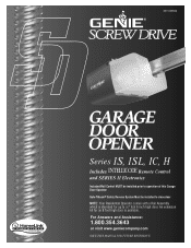
An extension kit for up to a 7 foot 6 inch high door. For Answers and Assistance: 1.800.354.3643 or visit www.geniecompany.com SAVE THIS MANUAL FOR FUTURE REFERENCE 3511035556 ¤® Series IS, ISL, IC, H Includes Remote Control and SERIES II Electronics Included Wall Control MUST be installed prior to operation of this Garage Door Operator Safe-T-Beam® Safety Reverse System Must be installed to close door NOTE: Your Residential Operator comes with a Rail Assembly which is standard for an 8 foot high door is available.
An extension kit for up to a 7 foot 6 inch high door. For Answers and Assistance: 1.800.354.3643 or visit www.geniecompany.com SAVE THIS MANUAL FOR FUTURE REFERENCE 3511035556 ¤® Series IS, ISL, IC, H Includes Remote Control and SERIES II Electronics Included Wall Control MUST be installed prior to operation of this Garage Door Operator Safe-T-Beam® Safety Reverse System Must be installed to close door NOTE: Your Residential Operator comes with a Rail Assembly which is standard for an 8 foot high door is available.
Owner's Manual
Page 2
... installing your new unit will be addressed. 2 They are planning to "do -it-yourself " installation. DO NOT USE A PORTABLE GENERATOR! Whether you are replacing an existing garage door operator or installing an operator in the exact position needed with your garage for installation on your garage does not have it adjusted by calling 1.800.355.3515. It may not be mounted. Ensure that you are as gate operators, garage door openers, entry door locks, security...
... installing your new unit will be addressed. 2 They are planning to "do -it-yourself " installation. DO NOT USE A PORTABLE GENERATOR! Whether you are replacing an existing garage door operator or installing an operator in the exact position needed with your garage for installation on your garage does not have it adjusted by calling 1.800.355.3515. It may not be mounted. Ensure that you are as gate operators, garage door openers, entry door locks, security...
Owner's Manual
Page 4
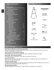
...-INSTALLATION WARNING 9 1 MAIN ASSEMBLY 10-14 2 INSTALLATION 15-21 3 SAFE-T-BEAM 22-23 4 WALL CONTROL 24-25 5 LIGHT & LIGHT LENS 25 6 CONNECTING POWER 26 7 SETTINGS 27-28 CONTACT REVERSE 28 8 BATTERY & VISOR CLIP 28 9 PROGRAMMING REMOTE CONTROLS 29 TRANSMITTER COMPLIANCE STATEMENT 30 IMPORTANT SAFETY INSTRUCTIONS 30 10 MAINTENANCE & TROUBLESHOOTING 31-32 11 WIRING DIAGRAM A WARRANTY B ACCESSORIES ORDER FORM C RECOMMENDED TOOLS Carpenter's level Step ladder Adjustable wrench Pencil Drill 5/ 32" Drill Bit Ratchet Wire strippers Phillips screwdriver 7/16...
...-INSTALLATION WARNING 9 1 MAIN ASSEMBLY 10-14 2 INSTALLATION 15-21 3 SAFE-T-BEAM 22-23 4 WALL CONTROL 24-25 5 LIGHT & LIGHT LENS 25 6 CONNECTING POWER 26 7 SETTINGS 27-28 CONTACT REVERSE 28 8 BATTERY & VISOR CLIP 28 9 PROGRAMMING REMOTE CONTROLS 29 TRANSMITTER COMPLIANCE STATEMENT 30 IMPORTANT SAFETY INSTRUCTIONS 30 10 MAINTENANCE & TROUBLESHOOTING 31-32 11 WIRING DIAGRAM A WARRANTY B ACCESSORIES ORDER FORM C RECOMMENDED TOOLS Carpenter's level Step ladder Adjustable wrench Pencil Drill 5/ 32" Drill Bit Ratchet Wire strippers Phillips screwdriver 7/16...
Owner's Manual
Page 5
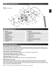
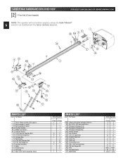
... used. Lighted Wall Button (some models) Works like a lighted wall button but includes a Vacation Lock Switch that disables all controls. Makes console easy to find in dark. NOTE: All items may not be opened and closed remotely. POWER HEAD EXPLODED VIEW [1] Power Head Assembly 49 E N D B C5 FOR HELP-1.800.354.3643 OR GENIECOMPANY.COM 41 F R 5 G P 48 A 42 K L 45 39 M H 4 J N POWER HEAD PARTS LIST Item Part Name 1 Power Head Assembly A Cover (By Series/Model) B Front Plate Assembly C Light Socket D Motor Parts E Receiver Assembly F Capacitor (By Series/Model...
... used. Lighted Wall Button (some models) Works like a lighted wall button but includes a Vacation Lock Switch that disables all controls. Makes console easy to find in dark. NOTE: All items may not be opened and closed remotely. POWER HEAD EXPLODED VIEW [1] Power Head Assembly 49 E N D B C5 FOR HELP-1.800.354.3643 OR GENIECOMPANY.COM 41 F R 5 G P 48 A 42 K L 45 39 M H 4 J N POWER HEAD PARTS LIST Item Part Name 1 Power Head Assembly A Cover (By Series/Model) B Front Plate Assembly C Light Socket D Motor Parts E Receiver Assembly F Capacitor (By Series/Model...
Owner's Manual
Page 6
... 13 Rail Strap 15A Open Limit Switch Assembly (Grey) Parts Required 1 Piece 3-Piece 1 1 1 1 1 1 1 2 2 2 2 1 1 4 8 5 13 1 1 2 2 1 1 1 1 PARTS LIST Item Part Name 15B Close Limit Switch Assembly (Brown) 16 No. 8-32 x 3/8" Hex Head Screw 17 Emergency Release Cord 18 Emergency Release Knob 19 Emergency Release Tag 20 Header Bracket 21 Door Bracket 22 1/4" x 2" Lag Screw 23 Straight Door Arm 24 Clevis Pin 25 Cotter Pin 26 Curved Door Arm 27 3/8" x 7/8" Hex Head Bolt 28 3/8" Hex Flange Nut 29 Wire 30 Insulated Staple 31 Wall Button Parts Required...
... 13 Rail Strap 15A Open Limit Switch Assembly (Grey) Parts Required 1 Piece 3-Piece 1 1 1 1 1 1 1 2 2 2 2 1 1 4 8 5 13 1 1 2 2 1 1 1 1 PARTS LIST Item Part Name 15B Close Limit Switch Assembly (Brown) 16 No. 8-32 x 3/8" Hex Head Screw 17 Emergency Release Cord 18 Emergency Release Knob 19 Emergency Release Tag 20 Header Bracket 21 Door Bracket 22 1/4" x 2" Lag Screw 23 Straight Door Arm 24 Clevis Pin 25 Cotter Pin 26 Curved Door Arm 27 3/8" x 7/8" Hex Head Bolt 28 3/8" Hex Flange Nut 29 Wire 30 Insulated Staple 31 Wall Button Parts Required...
Owner's Manual
Page 7
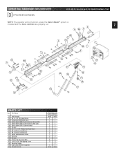
... VIEW [3] 3-Piece Rail & Screw Assembly FOR HELP-1.800.354.3643 OR GENIECOMPANY.COM NOTE: The operator will not function unless the Safe-T-Beam® system is installed and the force controls are properly set. 7 6 16 ...PARTS LIST Item Part Name 33 Wall Console 34 #6 x 1-1/4" Pan Head Screw 35 Entrapment WARNING Label 36 Safe-T-Beam (STB) System Sensor (Green LED) 37 Safe-T-Beam (STB) System Source (Red LED) 38 Safe-T-Beam (STB) System Bracket 39 Coupler 40 No. 10 x 1 1/4" Phillips Hex Head Screw 41 #8 x 3/8" Hex Head Screw 42 #8 x 3/8" Pan Head Screw 43 Safety & Maintenance Guide 44 Wire...
... VIEW [3] 3-Piece Rail & Screw Assembly FOR HELP-1.800.354.3643 OR GENIECOMPANY.COM NOTE: The operator will not function unless the Safe-T-Beam® system is installed and the force controls are properly set. 7 6 16 ...PARTS LIST Item Part Name 33 Wall Console 34 #6 x 1-1/4" Pan Head Screw 35 Entrapment WARNING Label 36 Safe-T-Beam (STB) System Sensor (Green LED) 37 Safe-T-Beam (STB) System Source (Red LED) 38 Safe-T-Beam (STB) System Bracket 39 Coupler 40 No. 10 x 1 1/4" Phillips Hex Head Screw 41 #8 x 3/8" Hex Head Screw 42 #8 x 3/8" Pan Head Screw 43 Safety & Maintenance Guide 44 Wire...
Owner's Manual
Page 9
... of opening while door is the size of springs IMPORTANT INSTALLATION under tension, and electric motors can cause injuries, your sales receipt with this manual. Install the entrapment WARNING label next to follow instruction. When replacing cover, make sure wires are not pinched or near moving parts of 5', so small children cannot reach it. • Away from all locks connected to the door before removing operator cover. Install the emergency release tag...
... of opening while door is the size of springs IMPORTANT INSTALLATION under tension, and electric motors can cause injuries, your sales receipt with this manual. Install the entrapment WARNING label next to follow instruction. When replacing cover, make sure wires are not pinched or near moving parts of 5', so small children cannot reach it. • Away from all locks connected to the door before removing operator cover. Install the emergency release tag...

Owner's Manual
Page 10
...]. • Peel protective paper from glue side of rail sections. DO NOT install Bumber. Fig. 1-4. • Turn screw until operator is facing up to 10 and including 7 feet 6 inches high. Set power head so that front panel (with 2 bolts [4] and 2 nuts [5], hand tight only. Keep rail sections level until it engages with shaft. (It will drop down over end of...
...]. • Peel protective paper from glue side of rail sections. DO NOT install Bumber. Fig. 1-4. • Turn screw until operator is facing up to 10 and including 7 feet 6 inches high. Set power head so that front panel (with 2 bolts [4] and 2 nuts [5], hand tight only. Keep rail sections level until it engages with shaft. (It will drop down over end of...

Owner's Manual
Page 14
... x 3/8" Hex head screw [44] Wire clip FOR HELP-1.800.354.3643 OR GENIECOMPANY.COM release knob Fig. 1-17 cord tag Fig. 1-18 B Fig. 1-19 "close" switch set aside for attaching light cover are included in emergency release lever (on side away from power head. (This means limit switches hang off opposite sides of rail. Use wire clip [44] to switch. Place "OPEN" limit switch over top of emergency release tag [19] through...
... x 3/8" Hex head screw [44] Wire clip FOR HELP-1.800.354.3643 OR GENIECOMPANY.COM release knob Fig. 1-17 cord tag Fig. 1-18 B Fig. 1-19 "close" switch set aside for attaching light cover are included in emergency release lever (on side away from power head. (This means limit switches hang off opposite sides of rail. Use wire clip [44] to switch. Place "OPEN" limit switch over top of emergency release tag [19] through...

Owner's Manual
Page 16
...; While raising garage door manually, watch top edge of door Fig. 2-4 This is called "highest point of door. 3. NOTE: Following step depends on centerline. Finding highest point of travel . Fig. 2-3. Final header bracket mounting location. • For SECTIONAL DOORS- centerline of door Fig. 2-3 centerline of door to see where it onto the rail. (A stool, chair, table or any object that can safely support door will also...
...; While raising garage door manually, watch top edge of door Fig. 2-4 This is called "highest point of door. 3. NOTE: Following step depends on centerline. Finding highest point of travel . Fig. 2-3. Final header bracket mounting location. • For SECTIONAL DOORS- centerline of door Fig. 2-3 centerline of door to see where it onto the rail. (A stool, chair, table or any object that can safely support door will also...
Owner's Manual
Page 22
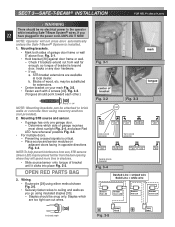
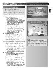
...local dealer. Wiring. • Route wire [29] using insulated staples [30]. - may be placed further from wall far enough, so tongue of bracket Fig. 3-2 SUN Fig. 3-3 tongue RED LED GREEN LED GREEN LED RED RED LED LED GREEN LED ONE DOOR GARAGE TWO DOOR GARAGE GREEN LED RED RED LED LED GREEN GREEN LED LED RED LED THREE DOOR GARAGE Fig. 3-4 Dashed Line = striped wire Solid Line = white wire Source Red LED Sensor Green LED Source Red LED Sensor Green LED A Power Head B Power Head Fig. 3-5 OPEN RED PARTS BAG 3. SECT 3-SAFE-T-BEAM ® INSTALLATION FOR HELP-1.800...
...local dealer. Wiring. • Route wire [29] using insulated staples [30]. - may be placed further from wall far enough, so tongue of bracket Fig. 3-2 SUN Fig. 3-3 tongue RED LED GREEN LED GREEN LED RED RED LED LED GREEN LED ONE DOOR GARAGE TWO DOOR GARAGE GREEN LED RED RED LED LED GREEN GREEN LED LED RED LED THREE DOOR GARAGE Fig. 3-4 Dashed Line = striped wire Solid Line = white wire Source Red LED Sensor Green LED Source Red LED Sensor Green LED A Power Head B Power Head Fig. 3-5 OPEN RED PARTS BAG 3. SECT 3-SAFE-T-BEAM ® INSTALLATION FOR HELP-1.800...

Owner's Manual
Page 24
... it. • Route wire from moving parts. - Split wires at power head and wall control • Connect wires to malfunction. Fig. 4-1. 3. Use pan head screws [34]. 5. Drive staples just tight enough to terminal # 1 - White wire to hold wire. 1. White wire to 1-1/2" Fig. 4-2 button Fig. 4-3 console Fig. 4-4 [34] #6 x 1-1/4" Pan head screw Mount wall control. Fig. 4-1 1/2" 1-1/4" to terminal "W" - NOTE: Use only staples included 2. Mount entrapment warning label. Striped wire to wall control. - Fig. 4-4. • Remove protective backing. •...
... it. • Route wire from moving parts. - Split wires at power head and wall control • Connect wires to malfunction. Fig. 4-1. 3. Use pan head screws [34]. 5. Drive staples just tight enough to terminal # 1 - White wire to hold wire. 1. White wire to 1-1/2" Fig. 4-2 button Fig. 4-3 console Fig. 4-4 [34] #6 x 1-1/4" Pan head screw Mount wall control. Fig. 4-1 1/2" 1-1/4" to terminal "W" - NOTE: Use only staples included 2. Mount entrapment warning label. Striped wire to wall control. - Fig. 4-4. • Remove protective backing. •...
Owner's Manual
Page 25
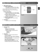
...! WALL CONTROL OPERATIONAL FEATURES 1. Install light bulbs. • 2 bulbs. - Door control button. - Opens and closes door from inside garage. - Wait until you have completed programming the Remote Controls. Wall console. NOTE: Carriage must stay in contact with 2 pan head screws. ([42] green parts bag). B. Turns operator lights on the metal front plate. • Lens will be fastened with "CLOSE" limit switch in order for : Rough service Vibration Appliances 2. Wall Button - Operates door from inside garage. No more than 60 watts each. - Whenever possible, use...
...! WALL CONTROL OPERATIONAL FEATURES 1. Install light bulbs. • 2 bulbs. - Door control button. - Opens and closes door from inside garage. - Wait until you have completed programming the Remote Controls. Wall console. NOTE: Carriage must stay in contact with 2 pan head screws. ([42] green parts bag). B. Turns operator lights on the metal front plate. • Lens will be fastened with "CLOSE" limit switch in order for : Rough service Vibration Appliances 2. Wall Button - Operates door from inside garage. No more than 60 watts each. - Whenever possible, use...

Owner's Manual
Page 26
CONNECT POWER WITH PERMANENT WIRING Instructions for electrician. 2. NOTE: Use only U.L. the brackets are not in proper alignment, the red LED (Source) will blink continuously. DO NOT alter the plug in door operator. • See warning above. • Plug door operator into alignment. Reconnect power to green wire (ground). CONNECT POWER WITH PLUG 9. To correct the problem - SECT 6-CONNECTING POWER WITH GROUNDED PLUG: WARNING To reduce the risk of black and white wire inside power head. Remove power from cover and...
CONNECT POWER WITH PERMANENT WIRING Instructions for electrician. 2. NOTE: Use only U.L. the brackets are not in proper alignment, the red LED (Source) will blink continuously. DO NOT alter the plug in door operator. • See warning above. • Plug door operator into alignment. Reconnect power to green wire (ground). CONNECT POWER WITH PLUG 9. To correct the problem - SECT 6-CONNECTING POWER WITH GROUNDED PLUG: WARNING To reduce the risk of black and white wire inside power head. Remove power from cover and...
Owner's Manual
Page 27
...carriage is between door and carriage. - Fig. 7-2. • Turn screw gently counterclockwise until it stops. • Run operator using wall control. • Observe door runs to the obstruction, garage door or garage door operator. If not, move "OPEN" limit switch toward carriage until lever is fully lifted. lever (actuator arm) fully lifted CARRIAGE SLIDE 27 SWITCH 1. Tighten limit switch set force adjustments at minimum required to "OPEN" limit switch. - Adjust closing force. • On front panel of power head to prevent being hit by pulling Emergency Release...
...carriage is between door and carriage. - Fig. 7-2. • Turn screw gently counterclockwise until it stops. • Run operator using wall control. • Observe door runs to the obstruction, garage door or garage door operator. If not, move "OPEN" limit switch toward carriage until lever is fully lifted. lever (actuator arm) fully lifted CARRIAGE SLIDE 27 SWITCH 1. Tighten limit switch set force adjustments at minimum required to "OPEN" limit switch. - Adjust closing force. • On front panel of power head to prevent being hit by pulling Emergency Release...
Owner's Manual
Page 28
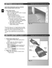
... Limit switch adjustments must be completed before running contact reverse test. 28 1. Test contact reverse. • Open door using wall control. - Fig. 7-3. • Close door using wall control. • Lay 2" x 4" board* on floor in on back of remote control. - c. until contact reverse works properly. SECT 8-BATTERY & VISOR CLIP FOR HELP-1.800.354.3643 OR GENIECOMPANY.COM 1. NOTE: Use only A23, 12 Volt battery. 2. Door should stop and reverse within 2 seconds of garage door opening. If door does not reverse properly: a. Decrease closing force...
... Limit switch adjustments must be completed before running contact reverse test. 28 1. Test contact reverse. • Open door using wall control. - Fig. 7-3. • Close door using wall control. • Lay 2" x 4" board* on floor in on back of remote control. - c. until contact reverse works properly. SECT 8-BATTERY & VISOR CLIP FOR HELP-1.800.354.3643 OR GENIECOMPANY.COM 1. NOTE: Use only A23, 12 Volt battery. 2. Door should stop and reverse within 2 seconds of garage door opening. If door does not reverse properly: a. Decrease closing force...
Owner's Manual
Page 29
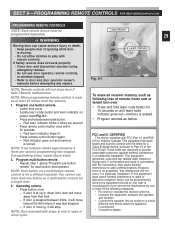
... 9-PROGRAMMING REMOTE CONTROLS FOR HELP-GENIECOMPANY.COM PROGRAMMING REMOTE CONTROLS NOTE: Each remote device must be at end of open or close door if Safe-T-Beam® malfunctions. If Safety reverse does not work properly: • Close door and disconnect operator using emergency release. • Do not use more than one button on , the user is encouraged to try to correct the interference by one button remote. • Lower lens cover. • Locate learn code button and learn indicator blinks 2 times per second, programming has stopped. Program...
... 9-PROGRAMMING REMOTE CONTROLS FOR HELP-GENIECOMPANY.COM PROGRAMMING REMOTE CONTROLS NOTE: Each remote device must be at end of open or close door if Safe-T-Beam® malfunctions. If Safety reverse does not work properly: • Close door and disconnect operator using emergency release. • Do not use more than one button on , the user is encouraged to try to correct the interference by one button remote. • Lower lens cover. • Locate learn code button and learn indicator blinks 2 times per second, programming has stopped. Program...
Owner's Manual
Page 30
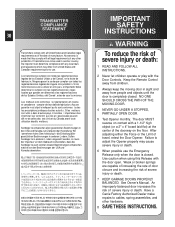
... of severe injury or death. 7 KEEP GARAGE DOORS PROPERLY BALANCED. Sendeger te entsprechen allen gesetzlichen Bestimmungen in anderen L ndern. Keep the Remote Control away from United States and Canadian requirements prior to use the Emergency Release only when the door is made that they comply with any other hardware. 8 SAVE THESE INSTRUCTIONS. If transmitters are capable of increasing the rate of...
... of severe injury or death. 7 KEEP GARAGE DOORS PROPERLY BALANCED. Sendeger te entsprechen allen gesetzlichen Bestimmungen in anderen L ndern. Keep the Remote Control away from United States and Canadian requirements prior to use the Emergency Release only when the door is made that they comply with any other hardware. 8 SAVE THESE INSTRUCTIONS. If transmitters are capable of increasing the rate of...
Owner's Manual
Page 31
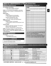
... contact with board. NOTE: If door fails to rail assembly. - CAUTION Use only GENIE GLU3 lubricant, because other lubricants may damage operator. HOLD WALL CONTROL BUTTON DOWN UNTIL DOOR IS CLOSED. (REMOTE CONTROL & WIRELESS KEYPAD WILL NOT WORK WITHOUT STB) CUSTOMER SERVICE: 1.800.354.3643 or www.geniecompany.com MONTH 31 J J JJJ JJJJJ J JJJJJ JJJJ Balance door. • Close door. • Release carriage from rail assembly. - If operator still fails, replace operator or HAVE THE OPERATOR SERVICED BY A PROFESSIONAL. Drive Screw • Lubricate drive screw. - One...
... contact with board. NOTE: If door fails to rail assembly. - CAUTION Use only GENIE GLU3 lubricant, because other lubricants may damage operator. HOLD WALL CONTROL BUTTON DOWN UNTIL DOOR IS CLOSED. (REMOTE CONTROL & WIRELESS KEYPAD WILL NOT WORK WITHOUT STB) CUSTOMER SERVICE: 1.800.354.3643 or www.geniecompany.com MONTH 31 J J JJJ JJJJJ J JJJJJ JJJJ Balance door. • Close door. • Release carriage from rail assembly. - If operator still fails, replace operator or HAVE THE OPERATOR SERVICED BY A PROFESSIONAL. Drive Screw • Lubricate drive screw. - One...
Owner's Manual
Page 32
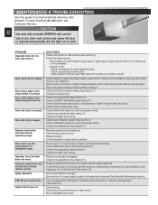
...-compatible wall control. MAINTENANCE & TROUBLESHOOTING Use this guide to maintain safe operation (See section 3). PROBLEM Operator does not run closed . If one remote control works and another does not, check battery, remote control type (Series II ) and frequency of buttons. If not, check fuse or circuit breaker. • If power is OK. Motor protector may be open . Check force adjustment (See Section 7). Check CLOSE limit switch for light beam obstruction or misalignment of any other wall control can short wires. Door will only run from receiver...
...-compatible wall control. MAINTENANCE & TROUBLESHOOTING Use this guide to maintain safe operation (See section 3). PROBLEM Operator does not run closed . If one remote control works and another does not, check battery, remote control type (Series II ) and frequency of buttons. If not, check fuse or circuit breaker. • If power is OK. Motor protector may be open . Check force adjustment (See Section 7). Check CLOSE limit switch for light beam obstruction or misalignment of any other wall control can short wires. Door will only run from receiver...


