
Owner's Manual
Page 4
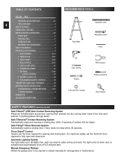
... Manual Emergency Release Allows the garage door to set the minimum force required to 60 Watts max. Safe-T-Stop® Timed Reversed System Automatically opens a closing door, if door does not close door. Force Guard® Control Used to be opened or closed manually for safer ... Carpenter's level Step ladder Adjustable wrench Pencil Drill 5/ 32" Drill Bit Ratchet Wire strippers Phillips screwdriver 7/16" and 9/16" Sockets Tape measure SAFETY FEATURES (varies by model) Safe-T-Beam® (STB) Non-Contact Reversing System Places an invisible beam across door opening and closing...
... Manual Emergency Release Allows the garage door to set the minimum force required to 60 Watts max. Safe-T-Stop® Timed Reversed System Automatically opens a closing door, if door does not close door. Force Guard® Control Used to be opened or closed manually for safer ... Carpenter's level Step ladder Adjustable wrench Pencil Drill 5/ 32" Drill Bit Ratchet Wire strippers Phillips screwdriver 7/16" and 9/16" Sockets Tape measure SAFETY FEATURES (varies by model) Safe-T-Beam® (STB) Non-Contact Reversing System Places an invisible beam across door opening and closing...
Owner's Manual
Page 5
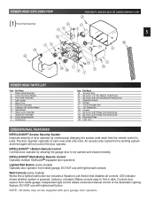
... each time the remote control is powered, locked or unlocked. Controls door opener from inside garage. POWER HEAD EXPLODED VIEW [1] Power Head Assembly 49 E N D B C5 FOR HELP-1.800.354.3643 OR GENIECOMPANY.COM 41 F R 5 G P 48 A 42 K L 45 39 M H 4 J N POWER HEAD PARTS LIST Item Part Name 1 Power Head Assembly A Cover (By Series/Model) B Front Plate Assembly...
... each time the remote control is powered, locked or unlocked. Controls door opener from inside garage. POWER HEAD EXPLODED VIEW [1] Power Head Assembly 49 E N D B C5 FOR HELP-1.800.354.3643 OR GENIECOMPANY.COM 41 F R 5 G P 48 A 42 K L 45 39 M H 4 J N POWER HEAD PARTS LIST Item Part Name 1 Power Head Assembly A Cover (By Series/Model) B Front Plate Assembly...
Owner's Manual
Page 9
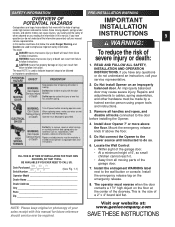
...ELECTRICAL SHOCK Turn off power before installing the Opener. 4. Install door Opener 7' or more above the floor. 5. SAFETY INFORMATION PRE-INSTALLATION WARNING OVERVIEW OF POTENTIAL HAZARDS Garage doors are large, heavy objects that move with the help of opening while door is moving. Since moving objects, springs ...next to follow , the words Danger, Warning, and Caution are used to indicate important steps to which door spring parts are not pinched or near moving parts of others depend on the floor at : www.geniecompany.com SAVE THESE INSTRUCTIONS CAUTION means that follow ...
...ELECTRICAL SHOCK Turn off power before installing the Opener. 4. Install door Opener 7' or more above the floor. 5. SAFETY INFORMATION PRE-INSTALLATION WARNING OVERVIEW OF POTENTIAL HAZARDS Garage doors are large, heavy objects that move with the help of opening while door is moving. Since moving objects, springs ...next to follow , the words Danger, Warning, and Caution are used to indicate important steps to which door spring parts are not pinched or near moving parts of others depend on the floor at : www.geniecompany.com SAVE THESE INSTRUCTIONS CAUTION means that follow ...

Owner's Manual
Page 16
... 16 highest point. With door held partly open (at centerline on type of travel." Measure from here to floor ONE-PIECE DOORS Highest point of door to see where it onto the rail. (A stool, chair, table or any object that can safely support door will also work.) - Fig...Following step depends on wall above door. add 6 inches to floor Fig. 2-2 +2-1/2" +6" Highest point of door Fig. 2-4 add 2-1/2 inches to the floor. • Remove support and gently lower door. • Mark "highest point of travel . • While raising garage door manually, watch top edge of ...
... 16 highest point. With door held partly open (at centerline on type of travel." Measure from here to floor ONE-PIECE DOORS Highest point of door to see where it onto the rail. (A stool, chair, table or any object that can safely support door will also work.) - Fig...Following step depends on wall above door. add 6 inches to floor Fig. 2-2 +2-1/2" +6" Highest point of door Fig. 2-4 add 2-1/2 inches to the floor. • Remove support and gently lower door. • Mark "highest point of travel . • While raising garage door manually, watch top edge of ...
Owner's Manual
Page 17
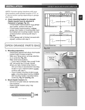
...bracket position is not solid, a mounting plate must be attached to wall studs remarked before continuing. centerline of garage. garage door opening OPEN ORANGE PARTS BAG TYPICAL FINISHED WALL floor Fig. 2-5 5. Mounting preparation. • Hold bracket against wall where final header...Check mounting location for rail strap 1/4" x 2" Lag screw Fig. 2-7 [22] header bracket header bracket garage door opening • If final header bracket position is on garage header door type. Mount header bracket [20]. • Drill 5/32 inch pilot holes at marked screw hole locations....
...bracket position is not solid, a mounting plate must be attached to wall studs remarked before continuing. centerline of garage. garage door opening OPEN ORANGE PARTS BAG TYPICAL FINISHED WALL floor Fig. 2-5 5. Mounting preparation. • Hold bracket against wall where final header...Check mounting location for rail strap 1/4" x 2" Lag screw Fig. 2-7 [22] header bracket header bracket garage door opening • If final header bracket position is on garage header door type. Mount header bracket [20]. • Drill 5/32 inch pilot holes at marked screw hole locations....
Owner's Manual
Page 22
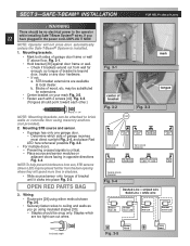
... prevent interference from sun, STB sensors (Green LED) may be substituted for extensions. • Center bracket on adjacent doors facing in opposite directions Fig. 3-4. OPEN RED PARTS BAG 3. Staples should be snug only. Blocks of garage door frame or wall 5" above floor. may be placed further from wall far enough, so tongue of bracket until...
... prevent interference from sun, STB sensors (Green LED) may be substituted for extensions. • Center bracket on adjacent doors facing in opposite directions Fig. 3-4. OPEN RED PARTS BAG 3. Staples should be snug only. Blocks of garage door frame or wall 5" above floor. may be placed further from wall far enough, so tongue of bracket until...
Owner's Manual
Page 25
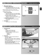
WALL CONTROL OPERATIONAL FEATURES 1. NOTE: Carriage must stay in contact with 2 pan head screws. ([42] green parts bag). Install light bulbs. • 2 bulbs. - A. Turns operator lights on shows system has power available and vacation switch is locked... into slots at bottom of lens Fig. 5-2 [42] #8 x 3/8" Pan head screw Vacation locking switch. - Opens and closes door from inside garage. - C. Wall Button - B. Operates door from inside garage. Check for alignment between the screw holes in front plate Fig. 5-1 pan head screws secure top of front plate....
WALL CONTROL OPERATIONAL FEATURES 1. NOTE: Carriage must stay in contact with 2 pan head screws. ([42] green parts bag). Install light bulbs. • 2 bulbs. - A. Turns operator lights on shows system has power available and vacation switch is locked... into slots at bottom of lens Fig. 5-2 [42] #8 x 3/8" Pan head screw Vacation locking switch. - Opens and closes door from inside garage. - C. Wall Button - B. Operates door from inside garage. Check for alignment between the screw holes in front plate Fig. 5-1 pan head screws secure top of front plate....
Owner's Manual
Page 27
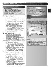
... obstruction, garage door or garage door operator. If not, increase closing force by pulling Emergency Release Lever toward carriage until door runs to achieve fully closed. 3. lever (actuator arm) fully lifted CARRIAGE SLIDE 27 SWITCH 1. Adjust opening force by moving parts. Set limit switch position. • Check door fully closed . - Fig. 7-1. - Fig. 7-1 CLOSE OPEN Fig. 7-2 NOTE: When the garage door is...
... obstruction, garage door or garage door operator. If not, increase closing force by pulling Emergency Release Lever toward carriage until door runs to achieve fully closed. 3. lever (actuator arm) fully lifted CARRIAGE SLIDE 27 SWITCH 1. Adjust opening force by moving parts. Set limit switch position. • Check door fully closed . - Fig. 7-1. - Fig. 7-1 CLOSE OPEN Fig. 7-2 NOTE: When the garage door is...


