

Owner's Manual
Page 1
... meets or exceeds all Federal, State and UL 325 Safety Requirements. Need Help? SAVEFTUHTIUSRMEARNEUFEARLEFNOCRE Please call us: 1-800-35-GENIE (354-3643) www.geniecompany.com Please have Model information ready when calling. 3531835447 TABLE OF CONTENTS Safety Information 2 Important ...Installation Instructions 2 Safety Features 2 Pre-installation Checklist 3 Garage Door Opener Assembly 9 Record Data (for 8' Doors Included Wall Control MUST be Properly Set to Operation of this Garage Door Operator...
... meets or exceeds all Federal, State and UL 325 Safety Requirements. Need Help? SAVEFTUHTIUSRMEARNEUFEARLEFNOCRE Please call us: 1-800-35-GENIE (354-3643) www.geniecompany.com Please have Model information ready when calling. 3531835447 TABLE OF CONTENTS Safety Information 2 Important ...Installation Instructions 2 Safety Features 2 Pre-installation Checklist 3 Garage Door Opener Assembly 9 Record Data (for 8' Doors Included Wall Control MUST be Properly Set to Operation of this Garage Door Operator...

Owner's Manual
Page 2
... the floor. Safe-T-Reverse® Contact Reversing System Automatically stops and reverses a closing door. Safe-T-Stop® Timed Reversed System Automatically opens a closing door, if door does not close door. Install the emergency release tag on you have garage door related questions or do... not understand an instruction, call 1-800-35-GENIE or visit www.geniecompany.com The light turns on an improperly balanced door. POTENTIAL HAZARD EFFECT PREVENTION MOVING DOOR WARNING: Can ...
... the floor. Safe-T-Reverse® Contact Reversing System Automatically stops and reverses a closing door. Safe-T-Stop® Timed Reversed System Automatically opens a closing door, if door does not close door. Install the emergency release tag on you have garage door related questions or do... not understand an instruction, call 1-800-35-GENIE or visit www.geniecompany.com The light turns on an improperly balanced door. POTENTIAL HAZARD EFFECT PREVENTION MOVING DOOR WARNING: Can ...
Owner's Manual
Page 3
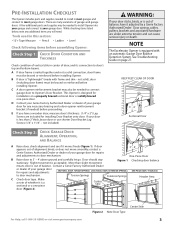
... door mechanism. Center Stile Figure 2 Note Door Type For Help, call 1-800-35-GENIE or visit www.geniecompany.com 3 NOTE The Excelerator Opener is a sectional or a one -piece door. C A door opener reinforcement bracket may be braced or reinforced before assembling Opener: Check Step 1: CHECK DOOR CONDITION AND THICKNESS Check condition of vertical stile in center...
... door mechanism. Center Stile Figure 2 Note Door Type For Help, call 1-800-35-GENIE or visit www.geniecompany.com 3 NOTE The Excelerator Opener is a sectional or a one -piece door. C A door opener reinforcement bracket may be braced or reinforced before assembling Opener: Check Step 1: CHECK DOOR CONDITION AND THICKNESS Check condition of vertical stile in center...
Owner's Manual
Page 4
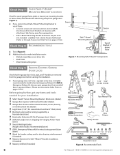
...reaches its highest point. • Measure distance ("H") from top edge of doors: - Mark this point on center line. Bottom of the garage door opening. Mark a point on center line. C Check wall for 8' door Figure 3 Rail Extension Kit SECTIONAL DOOR ONE-PIECE DOOR Figure 4 Find Highest Point...Header Bracket will be installed here. - B If your door height is long enough to connect points. Draw a center line to open the garage door. Bottom of Travel 4 For Help, call 1-800-35-GENIE or visit www.geniecompany.com Rail Extension for a stud or a solid header at 1-800-35...
...reaches its highest point. • Measure distance ("H") from top edge of doors: - Mark this point on center line. Bottom of the garage door opening. Mark a point on center line. C Check wall for 8' door Figure 3 Rail Extension Kit SECTIONAL DOOR ONE-PIECE DOOR Figure 4 Find Highest Point...Header Bracket will be installed here. - B If your door height is long enough to connect points. Draw a center line to open the garage door. Bottom of Travel 4 For Help, call 1-800-35-GENIE or visit www.geniecompany.com Rail Extension for a stud or a solid header at 1-800-35...
Owner's Manual
Page 5
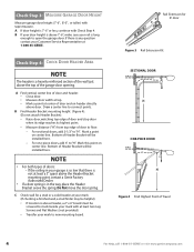
... widely. Contact a licensed electrician for your installation. For Help, call 1-800-35-GENIE or visit www.geniecompany.com 5 Not all Genie Factory Authorized Dealers are included to attach the Opener to most garage ceilings. Additional mounting straps or angle iron may be needed for installation...included) to install appropriate wiring in place of Power Cord. Check Step 5: CHECK POWER HEAD MOUNTING AREA Check ceiling or space above where Opener Power Head will be mounted (Figure 5): A Measure from garage door center line mark toward rear of garage: • Approximately 10' back...
... widely. Contact a licensed electrician for your installation. For Help, call 1-800-35-GENIE or visit www.geniecompany.com 5 Not all Genie Factory Authorized Dealers are included to attach the Opener to most garage ceilings. Additional mounting straps or angle iron may be needed for installation...included) to install appropriate wiring in place of Power Cord. Check Step 5: CHECK POWER HEAD MOUNTING AREA Check ceiling or space above where Opener Power Head will be mounted (Figure 5): A Measure from garage door center line mark toward rear of garage: • Approximately 10' back...
Owner's Manual
Page 6
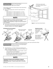
A If you open garage door from outside if there is highly recommended to install a Genie Emergency Release Kit (GER-2). available from garage door. • Safe-T-Beam® Mounting Bracket Extensions may be used (not included - A If your ...dealer) ❐ Lag Screws (11/4") for a wood door less than 2" thick (store) ❐ Electrical outlet and/or wiring (supplied by a licensed electrician) ❐ Excelerator Extension Kit (for 8' garage doors) (store) ❐ Sufficient angle iron or strapping for hanging Power Head (store) ❐ Two 60 Watt light bulbs (Rough service...
A If you open garage door from outside if there is highly recommended to install a Genie Emergency Release Kit (GER-2). available from garage door. • Safe-T-Beam® Mounting Bracket Extensions may be used (not included - A If your ...dealer) ❐ Lag Screws (11/4") for a wood door less than 2" thick (store) ❐ Electrical outlet and/or wiring (supplied by a licensed electrician) ❐ Excelerator Extension Kit (for 8' garage doors) (store) ❐ Sufficient angle iron or strapping for hanging Power Head (store) ❐ Two 60 Watt light bulbs (Rough service...

Owner's Manual
Page 7
...24 x 3/8" Hex Head No. 8-32 x 1" Phillips Screw No. 8-32 x 3/8" Slotted Hex Head Screw Power Cord For Help, call 1-800-35-GENIE or visit www.geniecompany.com 7 These items will be illustrated throughout the manual as required. Parts List Item 1 2 3 4 4A 4B 4C 8 9 10...Carriage Assembly (main carton) 1 1 Collar (blue bag) 3 Retaining Clip (blue bag) 3 Rail Strap (blue bag) 1 1 1/4"-20 Hex Head Bolt (blue bag) 2 2 Open Limit Switch Assembly (White)(green bag) 1 1 Close Limit Switch Assembly (Brown) (green bag) 1 1 No. 8-32 x 1" Hex Head Screw (green bag) 2 2 Emergency ...
...24 x 3/8" Hex Head No. 8-32 x 1" Phillips Screw No. 8-32 x 3/8" Slotted Hex Head Screw Power Cord For Help, call 1-800-35-GENIE or visit www.geniecompany.com 7 These items will be illustrated throughout the manual as required. Parts List Item 1 2 3 4 4A 4B 4C 8 9 10...Carriage Assembly (main carton) 1 1 Collar (blue bag) 3 Retaining Clip (blue bag) 3 Rail Strap (blue bag) 1 1 1/4"-20 Hex Head Bolt (blue bag) 2 2 Open Limit Switch Assembly (White)(green bag) 1 1 Close Limit Switch Assembly (Brown) (green bag) 1 1 No. 8-32 x 1" Hex Head Screw (green bag) 2 2 Emergency ...
Owner's Manual
Page 8
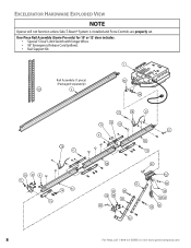
EXCELERATOR HARDWARE EXPLODED VIEW NOTE Opener will not function unless Safe-T-Beam® System is installed and Force Controls are properly set. One-Piece Rail Assembly (Genie Pro only) for 10' or 12' door includes: • Special "Close" Limit Switch with longer Wires. • 96" Emergency Release Cord (yellow). • Rail Support ... 99 45A 1100 46B 3311 30 28 556 3322 3366 3344 333 32 112 3333 2225 2222 23 2244 3355 8 For Help, call 1-800-35-GENIE or visit www.geniecompany.com
EXCELERATOR HARDWARE EXPLODED VIEW NOTE Opener will not function unless Safe-T-Beam® System is installed and Force Controls are properly set. One-Piece Rail Assembly (Genie Pro only) for 10' or 12' door includes: • Special "Close" Limit Switch with longer Wires. • 96" Emergency Release Cord (yellow). • Rail Support ... 99 45A 1100 46B 3311 30 28 556 3322 3366 3344 333 32 112 3333 2225 2222 23 2244 3355 8 For Help, call 1-800-35-GENIE or visit www.geniecompany.com
Owner's Manual
Page 9
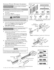
...) Hex Serrated Flange Nuts (Figure 10). E If you have a 1-piece rail unit, skip Assembly Step 2. See page 8.) C Attach End Rail Section to Opener Power Head. C Install Coupler on collar 11B. Finger-tighten until later. Engage Hooks Retaining Clips 14 Middle Rail Section 4B Arrows point toward Power Head... Assembly Step C1H: CONNECT RAIL TO POWER HEAD OPEN BLUE PARTS BAG A Turn Power Head upside down and place on Retaining Clip 10 Figure 11 Attach Middle Rail Section For Help, call 1-800-35-GENIE or visit www.geniecompany.com 9 Finger-tighten until later. (Middle Rail ...
...) Hex Serrated Flange Nuts (Figure 10). E If you have a 1-piece rail unit, skip Assembly Step 2. See page 8.) C Attach End Rail Section to Opener Power Head. C Install Coupler on collar 11B. Finger-tighten until later. Engage Hooks Retaining Clips 14 Middle Rail Section 4B Arrows point toward Power Head... Assembly Step C1H: CONNECT RAIL TO POWER HEAD OPEN BLUE PARTS BAG A Turn Power Head upside down and place on Retaining Clip 10 Figure 11 Attach Middle Rail Section For Help, call 1-800-35-GENIE or visit www.geniecompany.com 9 Finger-tighten until later. (Middle Rail ...

Owner's Manual
Page 10
.... End Rail Section 4C 8 Figure 13 Attach Rail Strap White Wire 21 Assembly Step C6H: INSTALL AND CONNECT LIMIT SWITCHES OPEN GREEN PARTS BAG A Turn Opener right side up and support Power Head to End Rail Section with arrow pointing away from Power Head (Figure 14). B Uncoil...Assembly 22 Wire Clips 53 19Brown Wire 24 Emergency Release Cord 25 C Place Switches on Assembled Rail 10 For Help, call 1-800-35-GENIE or visit www.geniecompany.com Assembly Step C3H: INSTALL MAGNETIC CARRIAGE ASSEMBLY ONTO RAILS A Place Magnetic Carriage Assembly Lever in "release" position. ...
.... End Rail Section 4C 8 Figure 13 Attach Rail Strap White Wire 21 Assembly Step C6H: INSTALL AND CONNECT LIMIT SWITCHES OPEN GREEN PARTS BAG A Turn Opener right side up and support Power Head to End Rail Section with arrow pointing away from Power Head (Figure 14). B Uncoil...Assembly 22 Wire Clips 53 19Brown Wire 24 Emergency Release Cord 25 C Place Switches on Assembled Rail 10 For Help, call 1-800-35-GENIE or visit www.geniecompany.com Assembly Step C3H: INSTALL MAGNETIC CARRIAGE ASSEMBLY ONTO RAILS A Place Magnetic Carriage Assembly Lever in "release" position. ...

Owner's Manual
Page 11
...TAG A Tie overhand knot at this manual for future reference should service ever be done later. H Turn Opener upside down, and connect Limit Switch Wires to call 1-800-35-GENIE or visit www.geniecompany.com 11 F Lay Wires in Magnetic Carriage Assembly Release Lever (Figure 16). D... Attach Emergency Release Tag to Magnetic Carriage Assembly Release Lever. 25 Emergency Release Tag Assembly Step C8H: RECORD OPENER MODEL AND SERIAL NUMBER Please...
...TAG A Tie overhand knot at this manual for future reference should service ever be done later. H Turn Opener upside down, and connect Limit Switch Wires to call 1-800-35-GENIE or visit www.geniecompany.com 11 F Lay Wires in Magnetic Carriage Assembly Release Lever (Figure 16). D... Attach Emergency Release Tag to Magnetic Carriage Assembly Release Lever. 25 Emergency Release Tag Assembly Step C8H: RECORD OPENER MODEL AND SERIAL NUMBER Please...
Owner's Manual
Page 12
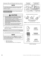
... 5/16-18 x 3/4" Hex Serrated Flange Nuts 28 Door Bracket 56 1/4"-20 x 3/4" Self-Drilling Screws Hardware (orange bag) 12 For Help, call 1-800-35-GENIE or visit www.geniecompany.com However, it is critical that the point where the Rail attaches to the garage framing. Installation SteCpH1: INSTALL HEADER BRACKET... Bracket. Do Not move the door spring. NOTE Mounting variations are shown in the way, place the Header Bracket above door. GARAGE DOOR OPENER INSTALLATION NOTE For lightweight garage doors, make sure you have sufficient support. • If a door spring is in Figure 18.
... 5/16-18 x 3/4" Hex Serrated Flange Nuts 28 Door Bracket 56 1/4"-20 x 3/4" Self-Drilling Screws Hardware (orange bag) 12 For Help, call 1-800-35-GENIE or visit www.geniecompany.com However, it is critical that the point where the Rail attaches to the garage framing. Installation SteCpH1: INSTALL HEADER BRACKET... Bracket. Do Not move the door spring. NOTE Mounting variations are shown in the way, place the Header Bracket above door. GARAGE DOOR OPENER INSTALLATION NOTE For lightweight garage doors, make sure you have sufficient support. • If a door spring is in Figure 18.

Owner's Manual
Page 13
...vs. See page 3. Check door condition and thickness. B Attach (5/16"-18) Flange Nut to Header Bracket For Help, call 1-800-35-GENIE or visit www.geniecompany.com 13 For sectional doors: A Place Door Bracket on top of your garage door. Installation SteCpH3: ATTACH RAIL TO... Power Head, place threaded end of masonite, lightweight wood, fiberglass, metal, or other lightweight materials must be properly braced before mounting door Opener. Installation SteCpH2: INSTALL GARAGE DOOR BRACKET CAUTION Doors made of Rail Strap Bolt through Header Bracket hole (Figure 20). the thickness of door...
...vs. See page 3. Check door condition and thickness. B Attach (5/16"-18) Flange Nut to Header Bracket For Help, call 1-800-35-GENIE or visit www.geniecompany.com 13 For sectional doors: A Place Door Bracket on top of your garage door. Installation SteCpH3: ATTACH RAIL TO... Power Head, place threaded end of masonite, lightweight wood, fiberglass, metal, or other lightweight materials must be properly braced before mounting door Opener. Installation SteCpH2: INSTALL GARAGE DOOR BRACKET CAUTION Doors made of Rail Strap Bolt through Header Bracket hole (Figure 20). the thickness of door...

Owner's Manual
Page 14
... 1"-11/2" between Rail and door at highest point of travel by raising the door to check. Read all fasteners now. Check for mounting Opener Power Head to garage ceiling. See Check Power Head Mounting Area on page 5. Extra material may vary. Do Not over-tighten. H Figure... 21 Checking Power Head position OPEN BEAM CEILING EXAMPLES Mounting Straps 30 55 11 Support board added for open beam and finished ceilings 14 For Help, call 1-800-35-GENIE or visit www.geniecompany.com Adjust as needed . C Install Mounting Straps and/...
... 1"-11/2" between Rail and door at highest point of travel by raising the door to check. Read all fasteners now. Check for mounting Opener Power Head to garage ceiling. See Check Power Head Mounting Area on page 5. Extra material may vary. Do Not over-tighten. H Figure... 21 Checking Power Head position OPEN BEAM CEILING EXAMPLES Mounting Straps 30 55 11 Support board added for open beam and finished ceilings 14 For Help, call 1-800-35-GENIE or visit www.geniecompany.com Adjust as needed . C Install Mounting Straps and/...

Owner's Manual
Page 15
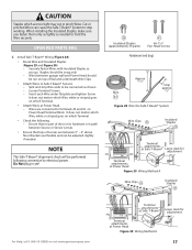
...Arms (SECTIONAL) As long as possible 35 32 Curved 36 34 Door Arm 31 Straight Door Arm 33 For Help, call 1-800-35-GENIE or visit www.geniecompany.com Figure 24 Assemble Arms (ONE-PIECE) 15 D Adjust height of children. WARNING Do Not skip Step D ...one-piece doors: A Attach Straight Arm to Magnetic Carriage Assembly. Securely tighten fasteners. Failure to 6' above ! Installation SteCpH5: ASSEMBLE AND CONNECT DOOR ARMS OPEN YELLOW PARTS BAG For sectional doors: A Attach Curved Door Arm to Magnetic Carriage Assembly. B Attach Straight Door Arm to Door Bracket with 2 (3/8" x...
...Arms (SECTIONAL) As long as possible 35 32 Curved 36 34 Door Arm 31 Straight Door Arm 33 For Help, call 1-800-35-GENIE or visit www.geniecompany.com Figure 24 Assemble Arms (ONE-PIECE) 15 D Adjust height of children. WARNING Do Not skip Step D ...one-piece doors: A Attach Straight Arm to Magnetic Carriage Assembly. Securely tighten fasteners. Failure to 6' above ! Installation SteCpH5: ASSEMBLE AND CONNECT DOOR ARMS OPEN YELLOW PARTS BAG For sectional doors: A Attach Curved Door Arm to Magnetic Carriage Assembly. B Attach Straight Door Arm to Door Bracket with 2 (3/8" x...

Owner's Manual
Page 16
... 6" above floor Figure 27 Final Check Safe-T-Beams® 16 For Help, call 1-800-35-GENIE or visit www.geniecompany.com may be placed further away from the door opening, where it now. Place Source and Sensor modules on this side whenever possible. • For ...). Installation SteCpH6: INSTALL SAFE-T-BEAM® SYSTEM ELECTRICAL WARNING Ensure there is critical. - NOTE The Opener will spend more time in opposite directions. Check if Bracket extends out from a Genie Factory Authorized Dealer or through the Accessories Order Form. - If not, Safe-TBeam® Mounting Bracket...
... 6" above floor Figure 27 Final Check Safe-T-Beams® 16 For Help, call 1-800-35-GENIE or visit www.geniecompany.com may be placed further away from the door opening, where it now. Place Source and Sensor modules on this side whenever possible. • For ...). Installation SteCpH6: INSTALL SAFE-T-BEAM® SYSTEM ELECTRICAL WARNING Ensure there is critical. - NOTE The Opener will spend more time in opposite directions. Check if Bracket extends out from a Genie Factory Authorized Dealer or through the Accessories Order Form. - If not, Safe-TBeam® Mounting Bracket...
Owner's Manual
Page 17
... will be run on Power Head Terminal Block. Do Not plug in path between 5" - 6" above floor. Brackets are too tight may cut or pinch Wires. OPEN RED PARTS BAG C Install Safe-T-Beam® Wiring (Figure 28): • Route Wire and Insulated Staples (Figure 29 and Figure 30). - Split and strip Wire...® Leave slack for adjustment Terminal attachments at Power Head Figure 29 Wiring Method A Wire Clips 53 Insulated Staples 38 For Help, call 1-800-35-GENIE or visit www.geniecompany.com 654321 STB Terminal attachments at Safe-T-Beam® Terminal attachments at Power Head. -
... will be run on Power Head Terminal Block. Do Not plug in path between 5" - 6" above floor. Brackets are too tight may cut or pinch Wires. OPEN RED PARTS BAG C Install Safe-T-Beam® Wiring (Figure 28): • Route Wire and Insulated Staples (Figure 29 and Figure 30). - Split and strip Wire...® Leave slack for adjustment Terminal attachments at Power Head Figure 29 Wiring Method A Wire Clips 53 Insulated Staples 38 For Help, call 1-800-35-GENIE or visit www.geniecompany.com 654321 STB Terminal attachments at Safe-T-Beam® Terminal attachments at Power Head. -

Owner's Manual
Page 18
...White Wire to Terminal 2 Striped Wire to Terminal 1 Terminal Attachment at location found above floor (to the Opener before installing Wall Console Wires. Installation SteCpH7: WALL CONSOLE INSTALLATION WARNING Verify there is no power to prevent...garage door). • Away from inside garage. • Independent Light Control allows convenient manual control of Opener Lighting System. Makes Console easy to find in as far as needed to wall near Wall Console. ...8226; At least 5' above with Entrapment Warning Label 18 For Help, call 1-800-35-GENIE or visit www.geniecompany.com
...White Wire to Terminal 2 Striped Wire to Terminal 1 Terminal Attachment at location found above floor (to the Opener before installing Wall Console Wires. Installation SteCpH7: WALL CONSOLE INSTALLATION WARNING Verify there is no power to prevent...garage door). • Away from inside garage. • Independent Light Control allows convenient manual control of Opener Lighting System. Makes Console easy to find in as far as needed to wall near Wall Console. ...8226; At least 5' above with Entrapment Warning Label 18 For Help, call 1-800-35-GENIE or visit www.geniecompany.com
Owner's Manual
Page 19
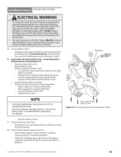
... here NOTE • Use only Underwriters Laboratories, Inc. (U.L.) recognized wire nuts. • The Circuit Boards are not installing permanent wiring, go to Opener Black Wire. - Remove Knock-Out Plug, Strain Relief, and Power Two Cord. (Cut Ground Wire on line side of Plug, Strain Relief, and...is glowing continuously (OK) or blinking (problem). • If Red LED is installed before energizing the Opener. White supply line to page 26.) For Help, call 1-800-35-GENIE or visit www.geniecompany.com 19 Four screws hold Motor Cover Figure 33 Connecting power with permanent wiring ...
... here NOTE • Use only Underwriters Laboratories, Inc. (U.L.) recognized wire nuts. • The Circuit Boards are not installing permanent wiring, go to Opener Black Wire. - Remove Knock-Out Plug, Strain Relief, and Power Two Cord. (Cut Ground Wire on line side of Plug, Strain Relief, and...is glowing continuously (OK) or blinking (problem). • If Red LED is installed before energizing the Opener. White supply line to page 26.) For Help, call 1-800-35-GENIE or visit www.geniecompany.com 19 Four screws hold Motor Cover Figure 33 Connecting power with permanent wiring ...
Owner's Manual
Page 20
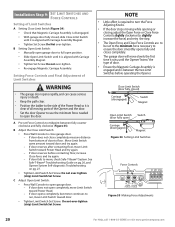
...Tighten Limit Switch Set Screw. If door does not open ) Carriage (disengaged) Magnet Figure 34 Setting Limit Switches Force Controls HI LO HI LO OPEN CLOSE FORCE FORCE Figure 35 Making Force Adjustments 20 For Help, call 1-800-35-GENIE or visit www.geniecompany.com Close Limit Switch (door... fully closed , slide Close Limit Switch until it is between fully counter clockwise and fully clockwise (Figure 35). B Setting Open Limit Switch: • Manually open garage door to close completely, measure...
...Tighten Limit Switch Set Screw. If door does not open ) Carriage (disengaged) Magnet Figure 34 Setting Limit Switches Force Controls HI LO HI LO OPEN CLOSE FORCE FORCE Figure 35 Making Force Adjustments 20 For Help, call 1-800-35-GENIE or visit www.geniecompany.com Close Limit Switch (door... fully closed , slide Close Limit Switch until it is between fully counter clockwise and fully clockwise (Figure 35). B Setting Open Limit Switch: • Manually open garage door to close completely, measure...


