

Owner's Manual
Page 1
Will not operate twice as fast on a one-piece door. Please call us: 1-800-35-GENIE (354-3643) www.geniecompany.com Please have Model information ready when calling. Extension Kit is available for Service 11 Garage Door Opener Installation 12 Accessories 22 Maintenance 25 Troubleshooting 26 Wiring Diagram 29 Warranty information 30 COMPLETE WITH INTELLICODE...
Will not operate twice as fast on a one-piece door. Please call us: 1-800-35-GENIE (354-3643) www.geniecompany.com Please have Model information ready when calling. Extension Kit is available for Service 11 Garage Door Opener Installation 12 Accessories 22 Maintenance 25 Troubleshooting 26 Wiring Diagram 29 Warranty information 30 COMPLETE WITH INTELLICODE...
Owner's Manual
Page 2
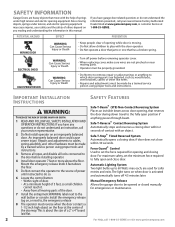
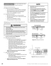
... Injury or Death • Keep people clear of opening and closing door within 30 seconds. Mount the emergency release knob 6 feet above the floor. each, are used for emergencies or maintenance. 2 For Help, call 1-800-35-GENIE or visit www.geniecompany.com An improperly balanced door could cause severe injury. Automatic Lighting System Two...
... Injury or Death • Keep people clear of opening and closing door within 30 seconds. Mount the emergency release knob 6 feet above the floor. each, are used for emergencies or maintenance. 2 For Help, call 1-800-35-GENIE or visit www.geniecompany.com An improperly balanced door could cause severe injury. Automatic Lighting System Two...
Owner's Manual
Page 3
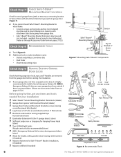
... skin - D Contact your door is acceptable. NOTE The Excelerator Opener is "lightweight" (made with an automatic Garage Door Balance Detection System. Slight movement is less than slight movement Figure 1 Checking door balance means door is a sectional or a one -piece door. C A door opener reinforcement bracket may be needed ) before installing Opener. E If you will need. If your Genie Factory Authorized Dealer or...
... skin - D Contact your door is acceptable. NOTE The Excelerator Opener is "lightweight" (made with an automatic Garage Door Balance Detection System. Slight movement is less than slight movement Figure 1 Checking door balance means door is a sectional or a one -piece door. C A door opener reinforcement bracket may be needed ) before installing Opener. E If you will need. If your Genie Factory Authorized Dealer or...
Owner's Manual
Page 4
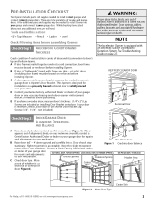
... on header directly above the top of Travel 4 For Help, call 1-800-35-GENIE or visit www.geniecompany.com A Find vertical center line of door and header: • Close door. • Measure door width at top. • Mark a point at least two Lag Screws and Flat Washers (... door height is long enough to "H". B If your rail is 7'-6" or less, continue with tape measure. If the ceiling in the way, place the Header Bracket avove the spring. C Check wall for 8' door Figure 3 Rail Extension Kit SECTIONAL DOOR ONE-PIECE DOOR Figure 4 Find Highest Point of the garage door opening....
... on header directly above the top of Travel 4 For Help, call 1-800-35-GENIE or visit www.geniecompany.com A Find vertical center line of door and header: • Close door. • Measure door width at top. • Mark a point at least two Lag Screws and Flat Washers (... door height is long enough to "H". B If your rail is 7'-6" or less, continue with tape measure. If the ceiling in the way, place the Header Bracket avove the spring. C Check wall for 8' door Figure 3 Rail Extension Kit SECTIONAL DOOR ONE-PIECE DOOR Figure 4 Find Highest Point of the garage door opening....
Owner's Manual
Page 5
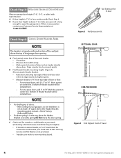
...wiring must be mounted (Figure 5): A Measure from garage door center line mark toward rear of Power Head. 10' for 7-1/2' doors 11' for 8' doors Door Center Line Figure 5 Check Power Head location OPEN BEAM CEILING EX AMPLES Mounting Straps 30 55 11 Support...door. Check Step 5: CHECK POWER HEAD MOUNTING AREA Check ceiling or space above where Opener Power Head will be installed by a Licensed Electrician. Contact a licensed electrician for open beam and finished ceilings Check Step 6: CHECK CEILING FOR GROUNDED POWER SOURCE A Check that there is a Licensed Electrician. Not all Genie...
...wiring must be mounted (Figure 5): A Measure from garage door center line mark toward rear of Power Head. 10' for 7-1/2' doors 11' for 8' doors Door Center Line Figure 5 Check Power Head location OPEN BEAM CEILING EX AMPLES Mounting Straps 30 55 11 Support...door. Check Step 5: CHECK POWER HEAD MOUNTING AREA Check ceiling or space above where Opener Power Head will be installed by a Licensed Electrician. Contact a licensed electrician for open beam and finished ceilings Check Step 6: CHECK CEILING FOR GROUNDED POWER SOURCE A Check that there is a Licensed Electrician. Not all Genie...
Owner's Manual
Page 6
... Mounting Bracket Extensions (dealer) ❐ Garage door opener reinforcement bracket (dealer) ❐ Garage door frame reinforcement brackets, screws, bracing or reinforcement kits (dealer) ❐ Lag Screws (11/4") for a wood door less than 2" thick (store) ❐ Electrical outlet and/or wiring (supplied by a licensed electrician) ❐ Excelerator Extension Kit (for 8' garage doors) (store) ❐ Sufficient angle iron...
... Mounting Bracket Extensions (dealer) ❐ Garage door opener reinforcement bracket (dealer) ❐ Garage door frame reinforcement brackets, screws, bracing or reinforcement kits (dealer) ❐ Lag Screws (11/4") for a wood door less than 2" thick (store) ❐ Electrical outlet and/or wiring (supplied by a licensed electrician) ❐ Excelerator Extension Kit (for 8' garage doors) (store) ❐ Sufficient angle iron...
Owner's Manual
Page 9
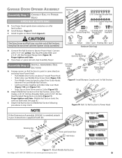
... Slip on Retaining Clip 10 Figure 11 Attach Middle Rail Section For Help, call 1-800-35-GENIE or visit www.geniecompany.com 9 C Install Coupler on a flat level surface. Keep Rail Sections level until the Opener is needed, attach it per instructions supplied with 2 (1/4"-20) (yellow) Hex Head Shoulder Bolts... 8 2 Figure 10 Bolt 1st Rail Section to Power Head NOTE If the Extension Assembly (GSXL8) is fully assembled. GARAGE DOOR OPENER ASSEMBLY Assembly Step C1H: CONNECT RAIL TO POWER HEAD OPEN BLUE PARTS BAG A Turn Power Head upside down and place on Motor Shaft (Figure 9).
... Slip on Retaining Clip 10 Figure 11 Attach Middle Rail Section For Help, call 1-800-35-GENIE or visit www.geniecompany.com 9 C Install Coupler on a flat level surface. Keep Rail Sections level until the Opener is needed, attach it per instructions supplied with 2 (1/4"-20) (yellow) Hex Head Shoulder Bolts... 8 2 Figure 10 Bolt 1st Rail Section to Power Head NOTE If the Extension Assembly (GSXL8) is fully assembled. GARAGE DOOR OPENER ASSEMBLY Assembly Step C1H: CONNECT RAIL TO POWER HEAD OPEN BLUE PARTS BAG A Turn Power Head upside down and place on Motor Shaft (Figure 9).

Owner's Manual
Page 10
... now. D Place Close Limit Switch (Brown Wire) 15" from Power Head. Close Limit Switch (Brown wire) 19 DOOR Open Limit Switch (White wire) 18 DOOR 15" Arrows point DOOR toward door Wire Clip 53 15" #8-32 x 1" Hex Head Screws 21 Figure 14 Install Limit Switches on End Rail Section with... from Power Head (Figure 14). Insert (#8-32 x 1") Hex Head Screw into slot on Assembled Rail 10 For Help, call 1-800-35-GENIE or visit www.geniecompany.com B Tighten snugly but Do Not over -tighten. Close Limit Switch Assembly Emergency Release Knob Emergency Release Tag Hardware ...
... now. D Place Close Limit Switch (Brown Wire) 15" from Power Head. Close Limit Switch (Brown wire) 19 DOOR Open Limit Switch (White wire) 18 DOOR 15" Arrows point DOOR toward door Wire Clip 53 15" #8-32 x 1" Hex Head Screws 21 Figure 14 Install Limit Switches on End Rail Section with... from Power Head (Figure 14). Insert (#8-32 x 1") Hex Head Screw into slot on Assembled Rail 10 For Help, call 1-800-35-GENIE or visit www.geniecompany.com B Tighten snugly but Do Not over -tighten. Close Limit Switch Assembly Emergency Release Knob Emergency Release Tag Hardware ...
Owner's Manual
Page 12
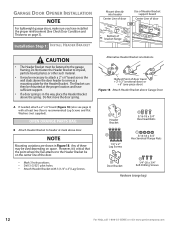
...18 x 3/4" Hex Head Bolts 11 5/16-18 x 3/4" Hex Serrated Flange Nuts 28 Door Bracket 56 1/4"-20 x 3/4" Self-Drilling Screws Hardware (orange bag) 12 For Help, call 1-800-35-GENIE or visit www.geniecompany.com Any of bracket flange CAUTION • The Header Bracket must ...the way, place the Header Bracket above the spring. GARAGE DOOR OPENER INSTALLATION NOTE For lightweight garage doors, make sure you have sufficient support. • If a door spring is in Figure 18. Alternative Header Bracket orientations Highest Point of the door. • Mark 3 hole positions. • Drill ...
...18 x 3/4" Hex Head Bolts 11 5/16-18 x 3/4" Hex Serrated Flange Nuts 28 Door Bracket 56 1/4"-20 x 3/4" Self-Drilling Screws Hardware (orange bag) 12 For Help, call 1-800-35-GENIE or visit www.geniecompany.com Any of bracket flange CAUTION • The Header Bracket must ...the way, place the Header Bracket above the spring. GARAGE DOOR OPENER INSTALLATION NOTE For lightweight garage doors, make sure you have sufficient support. • If a door spring is in Figure 18. Alternative Header Bracket orientations Highest Point of the door. • Mark 3 hole positions. • Drill ...

Owner's Manual
Page 13
... For Help, call 1-800-35-GENIE or visit www.geniecompany.com 13 For doors thinner than top roller, and mark holes (Figure 19). Finger-tighten until later. 28 30 56 or 30 28 SECTIONAL DOORS Center Line of door ONE-PIECE DOORS Center Line of door. For sectional doors: A Place Door Bracket on door center line, no OR lower...
... For Help, call 1-800-35-GENIE or visit www.geniecompany.com 13 For doors thinner than top roller, and mark holes (Figure 19). Finger-tighten until later. 28 30 56 or 30 28 SECTIONAL DOORS Center Line of door ONE-PIECE DOORS Center Line of door. For sectional doors: A Place Door Bracket on door center line, no OR lower...

Owner's Manual
Page 16
...Figure 26). - Check if Bracket extends out from a Genie Factory Authorized Dealer or through the Accessories Order Form. - NOTE To help prevent interference from the sun, the Safe-T-Beam® Sensor (Green LED) may be placed further away from the door opening, where it clicks into place Top of 6" Bracket 6"... above floor Figure 25 Install Safe-T-Beams® SUN RED LED GREEN LED GREEN LED RED RED LED LED GREEN LED ONE DOOR GARAGE TWO DOOR GARAGE GREEN LED RED RED LED LED ...
...Figure 26). - Check if Bracket extends out from a Genie Factory Authorized Dealer or through the Accessories Order Form. - NOTE To help prevent interference from the sun, the Safe-T-Beam® Sensor (Green LED) may be placed further away from the door opening, where it clicks into place Top of 6" Bracket 6"... above floor Figure 25 Install Safe-T-Beams® SUN RED LED GREEN LED GREEN LED RED RED LED LED GREEN LED ONE DOOR GARAGE TWO DOOR GARAGE GREEN LED RED RED LED LED ...

Owner's Manual
Page 18
... cause the Wall Console to Terminal #2. • On back of Opener Lighting System. CAUTION • Use of garage door. • At least 5' above with Entrapment Warning Label 18 For Help, call 1-800-35-GENIE or visit www.geniecompany.com F Remove protective backing from any wall ...consoles other than one lighted Wall Control per Opener will prevent the light from inside ...
... cause the Wall Console to Terminal #2. • On back of Opener Lighting System. CAUTION • Use of garage door. • At least 5' above with Entrapment Warning Label 18 For Help, call 1-800-35-GENIE or visit www.geniecompany.com F Remove protective backing from any wall ...consoles other than one lighted Wall Control per Opener will prevent the light from inside ...
Owner's Manual
Page 19
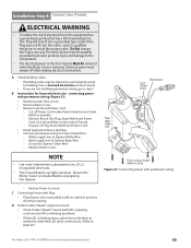
... not fit into a grounding type outlet. Dispose of electrical shock, this equipment has a grounding type Plug that has a third (grounding) Pin. The door Opener must remain off Power Cord inside Power Head as near Strain Relief as needed to make Red LED glow continuously. (Refer to page 26.) For... Help, call 1-800-35-GENIE or visit www.geniecompany.com 19 Installation SteCpH8: CONNECTING POWER ELECTRICAL WARNING • To reduce the risk of Plug, Strain Relief, and Power Cord...
... not fit into a grounding type outlet. Dispose of electrical shock, this equipment has a grounding type Plug that has a third (grounding) Pin. The door Opener must remain off Power Cord inside Power Head as near Strain Relief as needed to make Red LED glow continuously. (Refer to page 26.) For... Help, call 1-800-35-GENIE or visit www.geniecompany.com 19 Installation SteCpH8: CONNECTING POWER ELECTRICAL WARNING • To reduce the risk of Plug, Strain Relief, and Power Cord...
Owner's Manual
Page 20
...; If the door stops moving parts of the Opener and the door. • Set the door Opener to use the minimum force needed to open ) Carriage (disengaged) Magnet Figure 34 Setting Limit Switches Force Controls HI LO HI LO OPEN CLOSE FORCE FORCE Figure 35 Making Force Adjustments 20 For Help, call 1-800-35-GENIE or visit www...
...; If the door stops moving parts of the Opener and the door. • Set the door Opener to use the minimum force needed to open ) Carriage (disengaged) Magnet Figure 34 Setting Limit Switches Force Controls HI LO HI LO OPEN CLOSE FORCE FORCE Figure 35 Making Force Adjustments 20 For Help, call 1-800-35-GENIE or visit www...
Owner's Manual
Page 21
...checking the contact reverse function (Figure 36). If your Excelerator® is blocked, door will prevent the Timer/Cycle Counter from resetting. F Adjust Close Force to minimum needed to Close Limit Switch. - NOTE The door must be completed before the Carriage activates the Close Limit...4" board laid flat Figure 36 Checking Contact Reverse For Help, call 1-800-35-GENIE or visit www.geniecompany.com 21 D Test Door Opener: • Run door up and down a few times using Wall Console. D Check that door runs to Close Limit Switch. B Lay a 2" x 4" board flat in ...
...checking the contact reverse function (Figure 36). If your Excelerator® is blocked, door will prevent the Timer/Cycle Counter from resetting. F Adjust Close Force to minimum needed to Close Limit Switch. - NOTE The door must be completed before the Carriage activates the Close Limit...4" board laid flat Figure 36 Checking Contact Reverse For Help, call 1-800-35-GENIE or visit www.geniecompany.com 21 D Test Door Opener: • Run door up and down a few times using Wall Console. D Check that door runs to Close Limit Switch. B Lay a 2" x 4" board flat in ...
Owner's Manual
Page 22
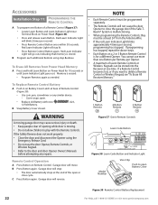
... 51 3 Button Remote 49 Figure 37 Genie Remote Controls Learn Code Button STATUS LEARN LEARN INDICATOR LIGHT Figure 38 Learn Code Button and Indicator Light Model Number Visor Clip Push to the door and door Opener Owner's Manuals before attempting any similar device. - Garage door will move. Garage door will go out, indicating that memory is...
... 51 3 Button Remote 49 Figure 37 Genie Remote Controls Learn Code Button STATUS LEARN LEARN INDICATOR LIGHT Figure 38 Learn Code Button and Indicator Light Model Number Visor Clip Push to the door and door Opener Owner's Manuals before attempting any similar device. - Garage door will move. Garage door will go out, indicating that memory is...
Owner's Manual
Page 23
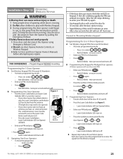
... Emergency Release. Press (in order) . - Red LED blinks - C Programming Door Openers: • Decide which door will blink. • Enter your PIN and try again. • Any keypad button will turn off . Learn Code Indicator LED (on next page) For Help, call 1-800-35-GENIE or visit www.geniecompany.com 23 Learn Code Indicator LED...
... Emergency Release. Press (in order) . - Red LED blinks - C Programming Door Openers: • Decide which door will blink. • Enter your PIN and try again. • Any keypad button will turn off . Learn Code Indicator LED (on next page) For Help, call 1-800-35-GENIE or visit www.geniecompany.com 23 Learn Code Indicator LED...
Owner's Manual
Page 24
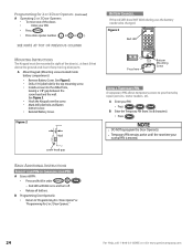
...etc. A Mount Keypad.(Mounting screws located inside battery compartment.) • Remove Battery Cover. A Enter your PIN. • Press . • Press door opener number ( or or ). Figure 2 1" 8 Wall screw head gap BATTERY CHANGES. Red LED will blink once and turn off. • Release all ... INSTRUCTIONS The Keypad must be changed. See Figure 3. • Drill a 1/16"pilot hole for 2 or 3 Door Openers." 24 For Help, call 1-800-35-GENIE or visit www.geniecompany.com BASIC ADDITIONAL INSTRUCTIONS FORGOT YOUR PIN OR CHANGING YOUR PIN. A Erase old PIN : •...
...etc. A Mount Keypad.(Mounting screws located inside battery compartment.) • Remove Battery Cover. A Enter your PIN. • Press . • Press door opener number ( or or ). Figure 2 1" 8 Wall screw head gap BATTERY CHANGES. Red LED will blink once and turn off. • Release all ... INSTRUCTIONS The Keypad must be changed. See Figure 3. • Drill a 1/16"pilot hole for 2 or 3 Door Openers." 24 For Help, call 1-800-35-GENIE or visit www.geniecompany.com BASIC ADDITIONAL INSTRUCTIONS FORGOT YOUR PIN OR CHANGING YOUR PIN. A Erase old PIN : •...
Owner's Manual
Page 26
... of increasing the rate of door closure and increasing the risk of severe injury or death. 7 KEEP GARAGE DOORS PROPERLY BALANCED. Have a Genie Factory Authorized Dealer make repairs to cables, spring assemblies, and other wall console can cause the Opener to operate unexpectedly and the ...light to adjust the Opener properly may cause severe injury or death. 6...
... of increasing the rate of door closure and increasing the risk of severe injury or death. 7 KEEP GARAGE DOORS PROPERLY BALANCED. Have a Genie Factory Authorized Dealer make repairs to cables, spring assemblies, and other wall console can cause the Opener to operate unexpectedly and the ...light to adjust the Opener properly may cause severe injury or death. 6...
Owner's Manual
Page 28
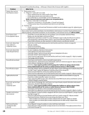
...Console or any shorting Staples and shorted Wires. • Was Remote Control lost or stolen? Check power source. Door Opener starts for service,or contact Customer Service at 1-800-35-GENIE. Adjust as needed . - Adjust as needed . • Check for shorted Wires. • Check garage... properly lubricated, and properly balanced as detailed in contact with the garage door hardware or springs,contact a Genie Factory Authorized De aler for service,or contact Customer Service at 1-800-35-GENIE. • Check Open Limit Switch for a short circuit and for proper wiring. • ...
...Console or any shorting Staples and shorted Wires. • Was Remote Control lost or stolen? Check power source. Door Opener starts for service,or contact Customer Service at 1-800-35-GENIE. Adjust as needed . - Adjust as needed . • Check for shorted Wires. • Check garage... properly lubricated, and properly balanced as detailed in contact with the garage door hardware or springs,contact a Genie Factory Authorized De aler for service,or contact Customer Service at 1-800-35-GENIE. • Check Open Limit Switch for a short circuit and for proper wiring. • ...


