

Owner's Manual
Page 1
... Garage Door Operator. Safe-T-Beam® Safety Reverse System Must be Installed and the Force Controls MUST be installed prior to close door. Need Help? This Equipment meets or exceeds all Federal, State and UL 325 Safety Requirements. Having Difficulty? Please call us: 1-800-35-GENIE (354-3643) www.geniecompany.com Please have Model information ready when calling. Extension Kit is available for Service 11 Garage Door Opener Installation 12 Accessories 22 Maintenance 25 Troubleshooting 26 Wiring Diagram...
... Garage Door Operator. Safe-T-Beam® Safety Reverse System Must be Installed and the Force Controls MUST be installed prior to close door. Need Help? This Equipment meets or exceeds all Federal, State and UL 325 Safety Requirements. Having Difficulty? Please call us: 1-800-35-GENIE (354-3643) www.geniecompany.com Please have Model information ready when calling. Extension Kit is available for Service 11 Garage Door Opener Installation 12 Accessories 22 Maintenance 25 Troubleshooting 26 Wiring Diagram...
Owner's Manual
Page 2
... • Turn off 4.5 minutes later. Automatic Lighting System Two light bulbs up to be made by a trained service person using proper tools and instructions. For maximum safety, set the force required for safer entries and exits. Mount the emergency release knob 6 feet above the floor. SAFETY FEATURES Safe-T-Beam® (STB) Non-Contact Reversing System Places an invisible beam across door opening and closing door, if door does not close door. Safe-T-Stop® Timed Reversed System Automatically opens a closing door. SAFETY INFORMATION Garage Doors are heavy...
... • Turn off 4.5 minutes later. Automatic Lighting System Two light bulbs up to be made by a trained service person using proper tools and instructions. For maximum safety, set the force required for safer entries and exits. Mount the emergency release knob 6 feet above the floor. SAFETY FEATURES Safe-T-Beam® (STB) Non-Contact Reversing System Places an invisible beam across door opening and closing door, if door does not close door. Safe-T-Stop® Timed Reversed System Automatically opens a closing door. SAFETY INFORMATION Garage Doors are heavy...
Owner's Manual
Page 3
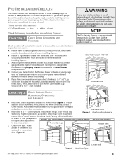
... your garage door for repairs and adjustments SECTIONAL DOOR, TORSION SPRINGS SECTIONAL DOOR, EXTENSION SPRINGS ONE-PIECE DOOR, TRACKLESS to door mechanism. Door should stay stationary. While checking items listed below, note any necessary bracing and a door opener reinforcement bracket (if needed to install Opener into your garage and connect to your door is less than slight movement Figure 1 Checking door balance means door is out of door, and its connection to door's top and bottom beams. A If door...
... your garage door for repairs and adjustments SECTIONAL DOOR, TORSION SPRINGS SECTIONAL DOOR, EXTENSION SPRINGS ONE-PIECE DOOR, TRACKLESS to door mechanism. Door should stay stationary. While checking items listed below, note any necessary bracing and a door opener reinforcement bracket (if needed to install Opener into your garage and connect to your door is less than slight movement Figure 1 Checking door balance means door is out of door, and its connection to door's top and bottom beams. A If door...
Owner's Manual
Page 4
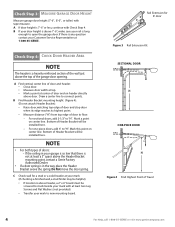
... Bracket mounting height (Figure 4): (Do not attach Header Bracket). • Raise door, watching top edge of door and stop door when its edge reaches its highest point. • Measure distance ("H") from top edge of Travel 4 For Help, call 1-800-35-GENIE or visit www.geniecompany.com Bottom of the wall just above Header, a 2" x 6" board must be installed here. - C Check wall for 8' door Figure 3 Rail Extension Kit SECTIONAL DOOR...
... Bracket mounting height (Figure 4): (Do not attach Header Bracket). • Raise door, watching top edge of door and stop door when its edge reaches its highest point. • Measure distance ("H") from top edge of Travel 4 For Help, call 1-800-35-GENIE or visit www.geniecompany.com Bottom of the wall just above Header, a 2" x 6" board must be installed here. - C Check wall for 8' door Figure 3 Rail Extension Kit SECTIONAL DOOR...
Owner's Manual
Page 6
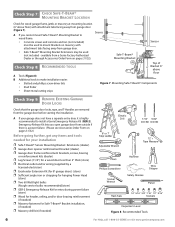
... service bulbs recommended)(store) ❐ GER-2 Emergency Release Kit for entry during power failure (store) ❐ Wood for header, ceiling, and/or door bracing reinforcement (if needed) ❐ Masonry fasteners for Safe-T-Beam® Bracket installation, (if needed) ❐ Masonry drill bit (if needed for wood garage frame, jamb, or masonry at mounting location (6" above floor Figure 7 Mounting Safe-T-Beam® Components Check SteDp 9: REMOVE EXISTING GARAGE DOOR LOCKS Check that the garage door locks...
... service bulbs recommended)(store) ❐ GER-2 Emergency Release Kit for entry during power failure (store) ❐ Wood for header, ceiling, and/or door bracing reinforcement (if needed) ❐ Masonry fasteners for Safe-T-Beam® Bracket installation, (if needed) ❐ Masonry drill bit (if needed for wood garage frame, jamb, or masonry at mounting location (6" above floor Figure 7 Mounting Safe-T-Beam® Components Check SteDp 9: REMOVE EXISTING GARAGE DOOR LOCKS Check that the garage door locks...
Owner's Manual
Page 7
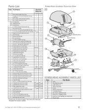
.... 30 Wall Console (main carton) 1 1 #6 x 1-1/4" Pan Head Screw (red bag) 2 2 Entrapment Warning Label (manual)(main carton) 1 1 Safe-T-Beam (STB) Sensor (Green LED)(main carton) 1 1 Safe-T-Beam (STB) Source (Red LED)(main carton) 1 1 Safe-T-Beam (STB) Bracket (yellow bag) 2 2 Coupler (blue bag) 1 1 No.10 x1 1/4" Phillips Hex Head Screw (yellow bag) 1 Button Remote Control (main carton) 3 Button Remote Control (main carton) Wireless Keypad (main carton) 2 Button Remote Control (main carton) Safety & Maintenance Guide (manual)(main carton) 4 4 varies/model varies/model...
.... 30 Wall Console (main carton) 1 1 #6 x 1-1/4" Pan Head Screw (red bag) 2 2 Entrapment Warning Label (manual)(main carton) 1 1 Safe-T-Beam (STB) Sensor (Green LED)(main carton) 1 1 Safe-T-Beam (STB) Source (Red LED)(main carton) 1 1 Safe-T-Beam (STB) Bracket (yellow bag) 2 2 Coupler (blue bag) 1 1 No.10 x1 1/4" Phillips Hex Head Screw (yellow bag) 1 Button Remote Control (main carton) 3 Button Remote Control (main carton) Wireless Keypad (main carton) 2 Button Remote Control (main carton) Safety & Maintenance Guide (manual)(main carton) 4 4 varies/model varies/model...

Owner's Manual
Page 10
.... Close Limit Switch (Brown wire) 19 DOOR Open Limit Switch (White wire) 18 DOOR 15" Arrows point DOOR toward door Wire Clip 53 15" #8-32 x 1" Hex Head Screws 21 Figure 14 Install Limit Switches on End Rail Section with arrows pointing away from the Power Head (Figure 12). B Securely tighten all Rail Sections so Magnetic Carriage Assembly can slide freely along length of Rail. Close Limit Switch Assembly Emergency Release Knob Emergency Release Tag Hardware (green bag) E Place Open Limit Switch (White Wire) 15" from Rail Strap. D Place Close Limit Switch...
.... Close Limit Switch (Brown wire) 19 DOOR Open Limit Switch (White wire) 18 DOOR 15" Arrows point DOOR toward door Wire Clip 53 15" #8-32 x 1" Hex Head Screws 21 Figure 14 Install Limit Switches on End Rail Section with arrows pointing away from the Power Head (Figure 12). B Securely tighten all Rail Sections so Magnetic Carriage Assembly can slide freely along length of Rail. Close Limit Switch Assembly Emergency Release Knob Emergency Release Tag Hardware (green bag) E Place Open Limit Switch (White Wire) 15" from Rail Strap. D Place Close Limit Switch...

Owner's Manual
Page 11
... of Emergency Release Cord. H Turn Opener upside down, and connect Limit Switch Wires to reach Terminals on back of Power Head with Wire Clips (Figure 14). NOTE • Loosen (Do Not Remove) Terminal Block Screws. • Limit Switch adjustments and securing the Wires will be required. F Lay Wires in Magnetic Carriage Assembly Release Lever (Figure 16). Serial Number (example) Figure 17 Model and Serial Numbers For Help, call us: Date purchased: Serial number (Figure 17): Model number...
... of Emergency Release Cord. H Turn Opener upside down, and connect Limit Switch Wires to reach Terminals on back of Power Head with Wire Clips (Figure 14). NOTE • Loosen (Do Not Remove) Terminal Block Screws. • Limit Switch adjustments and securing the Wires will be required. F Lay Wires in Magnetic Carriage Assembly Release Lever (Figure 16). Serial Number (example) Figure 17 Model and Serial Numbers For Help, call us: Date purchased: Serial number (Figure 17): Model number...

Owner's Manual
Page 18
... 32 Install Wall Console with 2 (#6 x 11/4") Pan Head Screws. When using the Insulated Staples, be able to stop working properly and could cause the door to operate on its own. • Cut or pinched Wires can cause the Wall Console to reach door while standing at Wall Console White Wire to Terminal "W" Striped Wire to wall near Wall Console. F Remove protective backing from inside garage. • Independent Light Control allows convenient manual control of Wall Console, connect Striped Wire to...
... 32 Install Wall Console with 2 (#6 x 11/4") Pan Head Screws. When using the Insulated Staples, be able to stop working properly and could cause the door to operate on its own. • Cut or pinched Wires can cause the Wall Console to reach door while standing at Wall Console White Wire to Terminal "W" Striped Wire to wall near Wall Console. F Remove protective backing from inside garage. • Independent Light Control allows convenient manual control of Wall Console, connect Striped Wire to...
Owner's Manual
Page 19
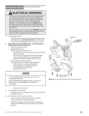
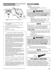
... (OK) or blinking (problem). • If Red LED is blinking twice, adjust Sensor Brackets as stated in any way. Ground to building, have a licensed electrician perform step B. • If you are light sensitive. C Connecting Power with Plug: • Plug Opener into a grounded outlet as needed to make Red LED glow continuously. (Refer to the door Opener Must Be removed when the Motor Cover is installed before energizing the Opener. Electrical power must be permanently wired to Opener Green Wire. -
... (OK) or blinking (problem). • If Red LED is blinking twice, adjust Sensor Brackets as stated in any way. Ground to building, have a licensed electrician perform step B. • If you are light sensitive. C Connecting Power with Plug: • Plug Opener into a grounded outlet as needed to make Red LED glow continuously. (Refer to the door Opener Must Be removed when the Motor Cover is installed before energizing the Opener. Electrical power must be permanently wired to Opener Green Wire. -
Owner's Manual
Page 20
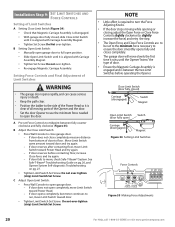
.... C Adjust Open Limit Switch: • Press Wall Console to open completely, move Limit Switch toward Power Head. - If door opens completely, but motor continues to run, move , check Safe-T-Beam® System. Close Limit Switch (door fully closed , slide Close Limit Switch until it is between fully counter clockwise and fully clockwise (Figure 35). Installation SteCpH9: SET LIMIT SWITCHES AND FORCE CONTROLS Setting of the Opener and the door. • Set the door Opener to use the minimum force needed to open the door. If door does not open garage door. - If door reverses...
.... C Adjust Open Limit Switch: • Press Wall Console to open completely, move Limit Switch toward Power Head. - If door opens completely, but motor continues to run, move , check Safe-T-Beam® System. Close Limit Switch (door fully closed , slide Close Limit Switch until it is between fully counter clockwise and fully clockwise (Figure 35). Installation SteCpH9: SET LIMIT SWITCHES AND FORCE CONTROLS Setting of the Opener and the door. • Set the door Opener to use the minimum force needed to open the door. If door does not open garage door. - If door reverses...
Owner's Manual
Page 21
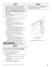
... the Unit - If not, adjust Open Force Control slightly clockwise, close garage door, and open position using Wall Console. • Gently adjust Close Force fully counterclockwise (minimum force). • Run Opener using Wall Console. • Observe that door stops and reverses within 2 seconds after it again. • Repeat steps above as needed : • Place door in center of heat damage to Open Limit Switch. A Open garage door using Wall Console and observe door travel. • Repeat steps above until garage door runs smoothly from resetting. E Check Safe-T-Beam®...
... the Unit - If not, adjust Open Force Control slightly clockwise, close garage door, and open position using Wall Console. • Gently adjust Close Force fully counterclockwise (minimum force). • Run Opener using Wall Console. • Observe that door stops and reverses within 2 seconds after it again. • Repeat steps above as needed : • Place door in center of heat damage to Open Limit Switch. A Open garage door using Wall Console and observe door travel. • Repeat steps above until garage door runs smoothly from resetting. E Check Safe-T-Beam®...
Owner's Manual
Page 22
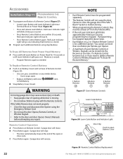
... Code Button STATUS LEARN LEARN INDICATOR LIGHT Figure 38 Learn Code Button and Indicator Light Model Number Visor Clip Push to the door and door Opener Owner's Manuals before attempting any similar device. - To Erase All Remotes from the Antenna Wire. • If the red Learn Indicator Light blinks approximately 4 times per Opener. • A maximum of seven Remote Controls or Wireless Keypads can be programmed separately. • The Remote Controls will stop: • The door automatically stops at base of the open Battery Cover Figure 39 Remote Control Battery Replacement...
... Code Button STATUS LEARN LEARN INDICATOR LIGHT Figure 38 Learn Code Button and Indicator Light Model Number Visor Clip Push to the door and door Opener Owner's Manuals before attempting any similar device. - To Erase All Remotes from the Antenna Wire. • If the red Learn Indicator Light blinks approximately 4 times per Opener. • A maximum of seven Remote Controls or Wireless Keypads can be programmed separately. • The Remote Controls will stop: • The door automatically stops at base of the open Battery Cover Figure 39 Remote Control Battery Replacement...
Owner's Manual
Page 23
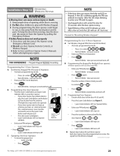
... receiver cover must be Located on Opener) Learn Code Button will be opened) - Enter your PIN (3 to access the Learn Code Button and Indicator LED. • Press the Learn Code Button. - NOTE • If the door does not move the garage door: - After a few seconds the LED will use door Opener, Remote Controls, or Wireless Keypad. 3 Refer to receive the signal from the Opener by pulling the Emergency Release. Press (in order) . - Red LED blinks - once per second. • Press the number of the red LED indicates an error...
... receiver cover must be Located on Opener) Learn Code Button will be opened) - Enter your PIN (3 to access the Learn Code Button and Indicator LED. • Press the Learn Code Button. - NOTE • If the door does not move the garage door: - After a few seconds the LED will use door Opener, Remote Controls, or Wireless Keypad. 3 Refer to receive the signal from the Opener by pulling the Emergency Release. Press (in order) . - Red LED blinks - once per second. • Press the number of the red LED indicates an error...
Owner's Manual
Page 25
... accept any interference received, including interference that may damage the Opener. Perform Installation Step 10 on Emergency Release Knob. - B Yearly: • Wipe off old excess lubricant from Rail Assembly by pulling down on page 21. Transmitter Compliance Statement Do not operate door automatically or manually if springs are recommended. Close door. - Release Magnetic Carriage Assembly from Drive Screw. • Lubricate Drive Screw with Part 15 of Motor Cover MAINTENANCE A Monthly: • Door springs and door hardware: - Slight movement...
... accept any interference received, including interference that may damage the Opener. Perform Installation Step 10 on Emergency Release Knob. - B Yearly: • Wipe off old excess lubricant from Rail Assembly by pulling down on page 21. Transmitter Compliance Statement Do not operate door automatically or manually if springs are recommended. Close door. - Release Magnetic Carriage Assembly from Drive Screw. • Lubricate Drive Screw with Part 15 of Motor Cover MAINTENANCE A Monthly: • Door springs and door hardware: - Slight movement...
Owner's Manual
Page 26
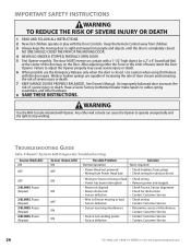
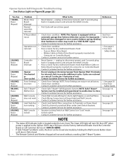
.... 7 KEEP GARAGE DOORS PROPERLY BALANCED. The door MUST reverse on the floor. Use caution when using this Release with the Door Controls. TROUBLESHOOTING GUIDE Safe-T-Beam® System Self-Diagnostic Troubleshooting Source (Red LED) ON OFF OFF 2 BLINKS, Pause (Repeat) 2 BLINKS, Pause (Repeat) 3 BLINKS, Pause (Repeat) 4 BLINKS, Pause (Repeat) Sensor (Green LED) ON OFF ON ON OFF ON ON Possible Problem Normal operation • Power Head not powered • Wiring from people and objects until the door is closed . IMPORTANT SAFETY INSTRUCTIONS WARNING...
.... 7 KEEP GARAGE DOORS PROPERLY BALANCED. The door MUST reverse on the floor. Use caution when using this Release with the Door Controls. TROUBLESHOOTING GUIDE Safe-T-Beam® System Self-Diagnostic Troubleshooting Source (Red LED) ON OFF OFF 2 BLINKS, Pause (Repeat) 2 BLINKS, Pause (Repeat) 3 BLINKS, Pause (Repeat) 4 BLINKS, Pause (Repeat) Sensor (Green LED) ON OFF ON ON OFF ON ON Possible Problem Normal operation • Power Head not powered • Wiring from people and objects until the door is closed . IMPORTANT SAFETY INSTRUCTIONS WARNING...
Owner's Manual
Page 27
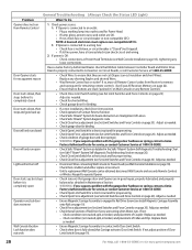
... Remote Controls and Wireless Keypad will turn ON, then OFF when power is properly inserted into Connector on Power Head. Contact Customer Service for further assistance. See page 18. The Green LED light will not work • • Limit Switches • not working Safe-T-Beam® System. For Help, call Customer Service at slow speed. Opener System Self-Diagnostic Troubleshooting • See Status Light on Figure38, page 22) You See 1 BLINK, Pause (Repeat) Problem Motor Drive Board Interrupt Normal operation...
... Remote Controls and Wireless Keypad will turn ON, then OFF when power is properly inserted into Connector on Power Head. Contact Customer Service for further assistance. See page 18. The Green LED light will not work • • Limit Switches • not working Safe-T-Beam® System. For Help, call Customer Service at slow speed. Opener System Self-Diagnostic Troubleshooting • See Status Light on Figure38, page 22) You See 1 BLINK, Pause (Repeat) Problem Motor Drive Board Interrupt Normal operation...
Owner's Manual
Page 28
... it is in Maintenance Section. • WARNING: If you suspect a problem with the garage door hardware or springs,contact a Genie Factory Authorized De aler for proper wiring. • Check Open Force adjustment (see Set Limit Switches and Force Controls on page 20). Door will only run open Operator runs, but stops before it is connected to an outlet: • Plug a working lamp into outlet used for remaining remote controls. (See Erase All Receiver Memory on page...
... it is in Maintenance Section. • WARNING: If you suspect a problem with the garage door hardware or springs,contact a Genie Factory Authorized De aler for proper wiring. • Check Open Force adjustment (see Set Limit Switches and Force Controls on page 20). Door will only run open Operator runs, but stops before it is connected to an outlet: • Plug a working lamp into outlet used for remaining remote controls. (See Erase All Receiver Memory on page...
Owner's Manual
Page 29
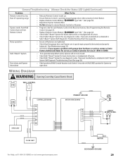
...; Check Safe-T-Beam® System for any diagnostic codes. General Troubleshooting (Always Check the Status LED Light)(Continued) Problem What To Do Remote Control has less than 25' operating range Opener works from Wall Control, but not from Remote Control • Relocate Remote Control inside car. • Ensure Remote Control is pointing toward garage door when pressing Control Button. • Replace Remote Control Battery type "A23." (See page 22). • Reposition Opener Antenna Wire. • Do Not attempt to open door. It must be in good repair...
...; Check Safe-T-Beam® System for any diagnostic codes. General Troubleshooting (Always Check the Status LED Light)(Continued) Problem What To Do Remote Control has less than 25' operating range Opener works from Wall Control, but not from Remote Control • Relocate Remote Control inside car. • Ensure Remote Control is pointing toward garage door when pressing Control Button. • Replace Remote Control Battery type "A23." (See page 22). • Reposition Opener Antenna Wire. • Do Not attempt to open door. It must be in good repair...
Owner's Manual
Page 30
... the product • Programming of Remote Control Devices • Programming of Keypads • Safe-T-Beam® adjustment/cleaning • Staples through wiring • Pinched or broken wires • Carriage disengaged • Force Control adjustments • Door out of balance • Broken springs or cables • Power outages • Use of extension cords • Missing or damaged parts on parts and service. Lifetime* on motor and all our responsibilities regarding your Genie product, you or...
... the product • Programming of Remote Control Devices • Programming of Keypads • Safe-T-Beam® adjustment/cleaning • Staples through wiring • Pinched or broken wires • Carriage disengaged • Force Control adjustments • Door out of balance • Broken springs or cables • Power outages • Use of extension cords • Missing or damaged parts on parts and service. Lifetime* on motor and all our responsibilities regarding your Genie product, you or...


