
Owner's Manual
Page 7
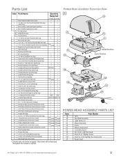
...No. 10-24 x 3/8" Hex Head No. 8-32 x 1" Phillips Screw No. 8-32 x 3/8" Slotted Hex Head Screw Power Cord For Help, call 1-800-35-GENIE or visit www.geniecompany.com 7 These items will be illustrated throughout the manual as required. Parts List Item 1 2 3 4 4A 4B 4C 8 9 10 11 ... (blue bag) 4 5/16"-18 x 11/16" Hex Head Shoulder Bolt (blue bag) 8 5/16"-18 Hex Serrated Flange Nut (blue & orange bags) varies/model 12 Magnetic Carriage Assembly (main carton) 1 1 Collar (blue bag) 3 Retaining Clip (blue bag) 3 Rail Strap (blue bag) 1 1 1/4"-20 Hex Head Bolt (blue bag) 2 2 ...
...No. 10-24 x 3/8" Hex Head No. 8-32 x 1" Phillips Screw No. 8-32 x 3/8" Slotted Hex Head Screw Power Cord For Help, call 1-800-35-GENIE or visit www.geniecompany.com 7 These items will be illustrated throughout the manual as required. Parts List Item 1 2 3 4 4A 4B 4C 8 9 10 11 ... (blue bag) 4 5/16"-18 x 11/16" Hex Head Shoulder Bolt (blue bag) 8 5/16"-18 Hex Serrated Flange Nut (blue & orange bags) varies/model 12 Magnetic Carriage Assembly (main carton) 1 1 Collar (blue bag) 3 Retaining Clip (blue bag) 3 Rail Strap (blue bag) 1 1 1/4"-20 Hex Head Bolt (blue bag) 2 2 ...

Owner's Manual
Page 10
...Power Head (Figure 14). Assembly Step C3H: INSTALL MAGNETIC CARRIAGE ASSEMBLY ONTO RAILS A Place Magnetic Carriage Assembly Lever in "release" position. B Slide Magnetic Carriage Assembly into slot on Assembled Rail 10 For Help, call 1-800-35-GENIE or visit www.geniecompany.com B Securely tighten all Rail Sections... so Magnetic Carriage Assembly can slide freely along length of Rail. D Place Close Limit Switch (Brown Wire) 15" from Power Head. Insert (#8-...
...Power Head (Figure 14). Assembly Step C3H: INSTALL MAGNETIC CARRIAGE ASSEMBLY ONTO RAILS A Place Magnetic Carriage Assembly Lever in "release" position. B Slide Magnetic Carriage Assembly into slot on Assembled Rail 10 For Help, call 1-800-35-GENIE or visit www.geniecompany.com B Securely tighten all Rail Sections... so Magnetic Carriage Assembly can slide freely along length of Rail. D Place Close Limit Switch (Brown Wire) 15" from Power Head. Insert (#8-...

Owner's Manual
Page 11
... end of Emergency Release Cord. C Tie overhand knot at one end of Emergency Release Cord. D Attach Emergency Release Tag to Magnetic Carriage Assembly Release Lever. 25 Emergency Release Tag Assembly Step C8H: RECORD OPENER MODEL AND SERIAL NUMBER Please note the following information so it...done later. Antenna Terminal Block White Limit Brown Limit Switch wires Switch wires Figure 15 Connect Limit Switch Wires to call 1-800-35-GENIE or visit www.geniecompany.com 11 Serial Number (example) Figure 17 Model and Serial Numbers For Help, call us: Date purchased: ...
... end of Emergency Release Cord. C Tie overhand knot at one end of Emergency Release Cord. D Attach Emergency Release Tag to Magnetic Carriage Assembly Release Lever. 25 Emergency Release Tag Assembly Step C8H: RECORD OPENER MODEL AND SERIAL NUMBER Please note the following information so it...done later. Antenna Terminal Block White Limit Brown Limit Switch wires Switch wires Figure 15 Connect Limit Switch Wires to call 1-800-35-GENIE or visit www.geniecompany.com 11 Serial Number (example) Figure 17 Model and Serial Numbers For Help, call us: Date purchased: ...

Owner's Manual
Page 15
...Cotter Pin (Figure 23). WARNING Do Not skip Step D above floor: • Pull Cord through Magnetic Carriage Assembly Lever until Knob is 6' from floor. • Tie a new overhand knot in Cord at Magnetic Carriage Assembly Lever. D Adjust height of Emergency Release Cord Knob to 6' above floor: • Pull Cord...Assemble Arms (SECTIONAL) As long as possible 35 32 Curved 36 34 Door Arm 31 Straight Door Arm 33 For Help, call 1-800-35-GENIE or visit www.geniecompany.com Figure 24 Assemble Arms (ONE-PIECE) 15 C Attach both Arms together with Clevis Pin and Cotter Pin (Figure 24...
...Cotter Pin (Figure 23). WARNING Do Not skip Step D above floor: • Pull Cord through Magnetic Carriage Assembly Lever until Knob is 6' from floor. • Tie a new overhand knot in Cord at Magnetic Carriage Assembly Lever. D Adjust height of Emergency Release Cord Knob to 6' above floor: • Pull Cord...Assemble Arms (SECTIONAL) As long as possible 35 32 Curved 36 34 Door Arm 31 Straight Door Arm 33 For Help, call 1-800-35-GENIE or visit www.geniecompany.com Figure 24 Assemble Arms (ONE-PIECE) 15 C Attach both Arms together with Clevis Pin and Cotter Pin (Figure 24...
Owner's Manual
Page 20
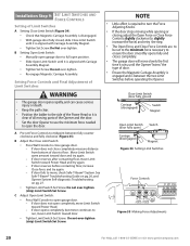
... B Adjust the Close Limit Switch: • Press Wall Console to full open position. • Slide Open Limit Switch until it is aligned with Carriage Assembly Magnet. • Tighten Set Screw. If door reverses before operating the Opener. C Adjust Open Limit Switch: • Press Wall Console to open...Magnet Open Limit Switch Switch (door fully open) Carriage (disengaged) Magnet Figure 34 Setting Limit Switches Force Controls HI LO HI LO OPEN CLOSE FORCE FORCE Figure 35 Making Force Adjustments 20 For Help, call 1-800-35-GENIE or visit www.geniecompany.com Move Limit Switch same ...
... B Adjust the Close Limit Switch: • Press Wall Console to full open position. • Slide Open Limit Switch until it is aligned with Carriage Assembly Magnet. • Tighten Set Screw. If door reverses before operating the Opener. C Adjust Open Limit Switch: • Press Wall Console to open...Magnet Open Limit Switch Switch (door fully open) Carriage (disengaged) Magnet Figure 34 Setting Limit Switches Force Controls HI LO HI LO OPEN CLOSE FORCE FORCE Figure 35 Making Force Adjustments 20 For Help, call 1-800-35-GENIE or visit www.geniecompany.com Move Limit Switch same ...
Owner's Manual
Page 21
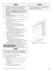
...the Close Limit Switch. 2" x 4" board laid flat Figure 36 Checking Contact Reverse For Help, call 1-800-35-GENIE or visit www.geniecompany.com 21 If your Excelerator® is blocked, door will prevent the Timer/Cycle Counter from Open Limit Switch to Close Limit Switch. simply ...Force Adjustments must contact the 2" x 4" board before checking the contact reverse function (Figure 36). NOTE The door must be completed before the Carriage activates the Close Limit Switch. A Open garage door using Wall Console. • Observe that door stops and reverses within 2 seconds after it ...
...the Close Limit Switch. 2" x 4" board laid flat Figure 36 Checking Contact Reverse For Help, call 1-800-35-GENIE or visit www.geniecompany.com 21 If your Excelerator® is blocked, door will prevent the Timer/Cycle Counter from Open Limit Switch to Close Limit Switch. simply ...Force Adjustments must contact the 2" x 4" board before checking the contact reverse function (Figure 36). NOTE The door must be completed before the Carriage activates the Close Limit Switch. A Open garage door using Wall Console. • Observe that door stops and reverses within 2 seconds after it ...
Owner's Manual
Page 25
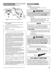
...Transmitter Compliance Statement Do not operate door automatically or manually if springs are recommended. Contact a Genie Factory Authorized Dealer for service or call Customer Service at 1-800-35-GENIE. - Release Magnetic Carriage Assembly from Drive Screw. • Lubricate Drive Screw with Part 15 of Motor Cover MAINTENANCE...Dealer for service or call 1-800-35-GENIE or visit www.geniecompany.com 25 Installation Step 13: INSTALL LIGHT BULBS AND LENS Snap Lens Hinges into slots on back of the FCC Rules. Reattach Magnetic Carriage Assembly to the following two conditions: (1) ...
...Transmitter Compliance Statement Do not operate door automatically or manually if springs are recommended. Contact a Genie Factory Authorized Dealer for service or call Customer Service at 1-800-35-GENIE. - Release Magnetic Carriage Assembly from Drive Screw. • Lubricate Drive Screw with Part 15 of Motor Cover MAINTENANCE...Dealer for service or call 1-800-35-GENIE or visit www.geniecompany.com 25 Installation Step 13: INSTALL LIGHT BULBS AND LENS Snap Lens Hinges into slots on back of the FCC Rules. Reattach Magnetic Carriage Assembly to the following two conditions: (1) ...
Owner's Manual
Page 28
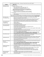
...Limit Switch for a short circuit and for remaining remote controls. (See Erase All Receiver Memory on page 20). A. Have a Genie Factory Authorized Dealer check that Carriage activates Close Limit Switch. Adjust as needed . • Check garage door for binding. • Check Open Limit Switch for... tightening any loose connections. Adjust as needed . • Ensure Magnetic Carriage Assembly is connected to Power Head (see Set Limit Switches and Force Controls on Circuit Boards, or call 1-800-35-GENIE or visit www.geniecompany.com Check condition (not cracked, split, or ...
...Limit Switch for a short circuit and for remaining remote controls. (See Erase All Receiver Memory on page 20). A. Have a Genie Factory Authorized Dealer check that Carriage activates Close Limit Switch. Adjust as needed . • Check garage door for binding. • Check Open Limit Switch for... tightening any loose connections. Adjust as needed . • Ensure Magnetic Carriage Assembly is connected to Power Head (see Set Limit Switches and Force Controls on Circuit Boards, or call 1-800-35-GENIE or visit www.geniecompany.com Check condition (not cracked, split, or ...
Owner's Manual
Page 30
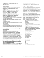
...• Programming of Keypads • Safe-T-Beam® adjustment/cleaning • Staples through wiring • Pinched or broken wires • Carriage disengaged • Force Control adjustments • Door out of balance • Broken springs or cables • Power outages • Use ... ISD990 Series - ISD995-2WKM Series - CMD9900 Series - Lifetime* on motor, all parts. If we send replacement parts for your Genie product. This warranty is non-transferable. There are considered replacement parts) • Installation • Commercial use new or reconditioned parts....
...• Programming of Keypads • Safe-T-Beam® adjustment/cleaning • Staples through wiring • Pinched or broken wires • Carriage disengaged • Force Control adjustments • Door out of balance • Broken springs or cables • Power outages • Use ... ISD990 Series - ISD995-2WKM Series - CMD9900 Series - Lifetime* on motor, all parts. If we send replacement parts for your Genie product. This warranty is non-transferable. There are considered replacement parts) • Installation • Commercial use new or reconditioned parts....


