
Owner's Manual
Page 3
... ADJUSTMENT 20-22 KEYED EMERGENCY RELEASE 21 CONTACT REVERSE TEST 22 7 PROGRAMMING REMOTE CONTROLS 23 8 BATTERY/VISOR CLIP INSTALLATION 24 9 LIGHT BULB AND LENS INSTALLATION 24 SAFETY INSTRUCTIONS 25 MAINTENANCE & TROUBLESHOOTING 10 ROUTINE MONTHLY MAINTENANCE 25 WIRING DIAGRAM 26 TROUBLESHOOTING GUIDE - Follow ...Safe-T-Reverse® Contact Reversing System. Automatically opens a closing door if a problem is detected. Red or green LED indicator lights on the power head provide a self diagnostic code if an operational problem exists. (Refer to each time the remote control is...
... ADJUSTMENT 20-22 KEYED EMERGENCY RELEASE 21 CONTACT REVERSE TEST 22 7 PROGRAMMING REMOTE CONTROLS 23 8 BATTERY/VISOR CLIP INSTALLATION 24 9 LIGHT BULB AND LENS INSTALLATION 24 SAFETY INSTRUCTIONS 25 MAINTENANCE & TROUBLESHOOTING 10 ROUTINE MONTHLY MAINTENANCE 25 WIRING DIAGRAM 26 TROUBLESHOOTING GUIDE - Follow ...Safe-T-Reverse® Contact Reversing System. Automatically opens a closing door if a problem is detected. Red or green LED indicator lights on the power head provide a self diagnostic code if an operational problem exists. (Refer to each time the remote control is...
Owner's Manual
Page 4
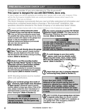
...damage to Section 2.) NOTE: Mounting brackets must be in the illustrations on page 5.) 1 Check your ceiling where the power head of aluminum, light-weight steel, fiberglass or glass panels? In many cases you will be mounted. Use this will be replacing an existing door opener with your... door. (See emergency release kit installation notes on page 21.) 4 PN# 3642036534, 02/26/2010 REV. 1 They are as follows: The Genie Company recommends that they can cause serious injury or death. Insure that your door is properly balanced and moving freely. (Refer to property - If ...
...damage to Section 2.) NOTE: Mounting brackets must be in the illustrations on page 5.) 1 Check your ceiling where the power head of aluminum, light-weight steel, fiberglass or glass panels? In many cases you will be mounted. Use this will be replacing an existing door opener with your... door. (See emergency release kit installation notes on page 21.) 4 PN# 3642036534, 02/26/2010 REV. 1 They are as follows: The Genie Company recommends that they can cause serious injury or death. Insure that your door is properly balanced and moving freely. (Refer to property - If ...
Owner's Manual
Page 7
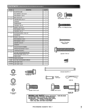
... BRACKET PHILLIPS HEX SCREW - #10-16 x 1- 1/4'' WIRE NUT (GREY) NO NUMBER REMOTE WITH BATTERY NO BAG Safe-T-Beam® SOURCE/SENSOR & WIRE SET NO NUMBER LIGHT COVER - IMPORTANT! - Please call toll free - 1.800.354.3643 DO NOT RETURN TO POINT OF PURCHASE. COLOR QUANTITY 2 8 8 3 1 1 1 2 5 5 2 3 1 3 1 2 1 1 1 2...5/16" x 3/4" Cotter pin Hex Bolt - 5/16"-18 x 3/4" Hex Bolt - 5/16"-18 x 1/2" MISSING ANY PARTS? WHITE NO NUMBER LIGHT COVER - Shown Full size (See Parts List below for full description.) BAG NO. Information needed when calling • Model number - (located on ...
... BRACKET PHILLIPS HEX SCREW - #10-16 x 1- 1/4'' WIRE NUT (GREY) NO NUMBER REMOTE WITH BATTERY NO BAG Safe-T-Beam® SOURCE/SENSOR & WIRE SET NO NUMBER LIGHT COVER - IMPORTANT! - Please call toll free - 1.800.354.3643 DO NOT RETURN TO POINT OF PURCHASE. COLOR QUANTITY 2 8 8 3 1 1 1 2 5 5 2 3 1 3 1 2 1 1 1 2...5/16" x 3/4" Cotter pin Hex Bolt - 5/16"-18 x 3/4" Hex Bolt - 5/16"-18 x 1/2" MISSING ANY PARTS? WHITE NO NUMBER LIGHT COVER - Shown Full size (See Parts List below for full description.) BAG NO. Information needed when calling • Model number - (located on ...
Owner's Manual
Page 14
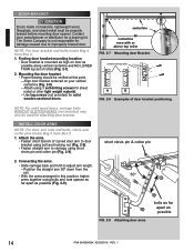
... doors, carriage bolts WITHOUT SLOTTED HEADS (not included) may also be used for sheet metal or other light weight material. - Contact door manufacturer or distributor for damage caused due to improperly braced door. The Genie Company is mounted as high on your vertical centerline (Fig. 2-8). - centerline of top roller A B FIG. 2-8 Examples of...
... doors, carriage bolts WITHOUT SLOTTED HEADS (not included) may also be used for sheet metal or other light weight material. - Contact door manufacturer or distributor for damage caused due to improperly braced door. The Genie Company is mounted as high on your vertical centerline (Fig. 2-8). - centerline of top roller A B FIG. 2-8 Examples of...
Owner's Manual
Page 15
... prevent small children from operating door. • It must be away from any other wall control can cause the door to operate unexpectedly and the light not to stop working. This is NO power to the + (plus ) terminal. - WARNING Use of wire routing when NOT pre-wired. Striped wire to the...
... prevent small children from operating door. • It must be away from any other wall control can cause the door to operate unexpectedly and the light not to stop working. This is NO power to the + (plus ) terminal. - WARNING Use of wire routing when NOT pre-wired. Striped wire to the...
Owner's Manual
Page 16
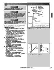
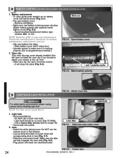
... of wire (Fig. 3-2 on wall near wall button. Route wall button wires through wire guide on the wire. Confirm wire lock by lightly tugging on power head. - FIG. 3-4 Mounting wall button. Insulated • If rear cover is located in the terminal hole. •...to wall with 2 screws (provided) (Fig. 3-4). • Remove protective backing from "Entrapment" warning label (Fig. 3-5). Insert wire into terminal holes and lightly press in locking clips.) The white wire into #1 terminal hole and striped wire into the #2 terminal hole. - 3.Securely fasten wires. • Securely ...
... of wire (Fig. 3-2 on wall near wall button. Route wall button wires through wire guide on the wire. Confirm wire lock by lightly tugging on power head. - FIG. 3-4 Mounting wall button. Insulated • If rear cover is located in the terminal hole. •...to wall with 2 screws (provided) (Fig. 3-4). • Remove protective backing from "Entrapment" warning label (Fig. 3-5). Insert wire into terminal holes and lightly press in locking clips.) The white wire into #1 terminal hole and striped wire into the #2 terminal hole. - 3.Securely fasten wires. • Securely ...
Owner's Manual
Page 18
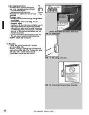
... Safe-T-Beam® wire to approximately one foot (1 ft) from ceiling to 'even' numbered terminal holes and striped wires into terminal holes and lightly press in the terminal hole. • Install rear cover. PB Infrared Sensor 65 432 1 - Use this time. (Power Head With Rear ... should remain in the orange locking clips above each terminal hole. (You can cut or pinch wires. NOTE: For rear cover locate Box 4. 5. Sensor Invisible Light Beam Sensor Protection Area FIG. 4-6 Wire routing. Insulated Staple Wall Red Source Wall Green Sensor Ceiling 6 5 4 3 2 1 or 6 5 4 3 2 1 Power ...
... Safe-T-Beam® wire to approximately one foot (1 ft) from ceiling to 'even' numbered terminal holes and striped wires into terminal holes and lightly press in the terminal hole. • Install rear cover. PB Infrared Sensor 65 432 1 - Use this time. (Power Head With Rear ... should remain in the orange locking clips above each terminal hole. (You can cut or pinch wires. NOTE: For rear cover locate Box 4. 5. Sensor Invisible Light Beam Sensor Protection Area FIG. 4-6 Wire routing. Insulated Staple Wall Red Source Wall Green Sensor Ceiling 6 5 4 3 2 1 or 6 5 4 3 2 1 Power ...
Owner's Manual
Page 19
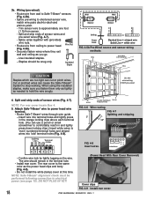
... to make adjustments. • The Red LED transmitter will be influenced if the Safe-T-Beam® is opening, its fully opened position. (Meanwhile, the opener light will only fit a grounded type outlet. hole and discard (Fig. 5-3). • Connect permanent wiring to its hardware is a misalignment. INFRARED PROTECTION FUNCTION 1. Motor Cover Screws... from the 7/8" dia. If building codes require door opener to its movement will have a qualified licensed electrician connect power with circuit breaker protection. NOTE: The Genie Company is closing movement.
... to make adjustments. • The Red LED transmitter will be influenced if the Safe-T-Beam® is opening, its fully opened position. (Meanwhile, the opener light will only fit a grounded type outlet. hole and discard (Fig. 5-3). • Connect permanent wiring to its hardware is a misalignment. INFRARED PROTECTION FUNCTION 1. Motor Cover Screws... from the 7/8" dia. If building codes require door opener to its movement will have a qualified licensed electrician connect power with circuit breaker protection. NOTE: The Genie Company is closing movement.
Owner's Manual
Page 20
... door slightly in the UP direction. 3. Once the door is fully closed when the bottom edge of the power head. LED Indicator Light Open Open Set Limit Travel Limit Button Up Force OPEN Control Adjustment To Garage Door SET LEARN MANUAL LIMIT FORCE SET Learn Code CODE... 3. Press and hold the "Close Travel Limit" button until the door is fully closed . 2. Door is in damage to Carriage. The LED indicator light will blink green once. OPEN TRAVEL LIMIT 1. SETTING & TESTING OPEN/CLOSE LIMITS The OPEN (UP) and CLOSE (DOWN) door positions are controlled by ...
... door slightly in the UP direction. 3. Once the door is fully closed when the bottom edge of the power head. LED Indicator Light Open Open Set Limit Travel Limit Button Up Force OPEN Control Adjustment To Garage Door SET LEARN MANUAL LIMIT FORCE SET Learn Code CODE... 3. Press and hold the "Close Travel Limit" button until the door is fully closed . 2. Door is in damage to Carriage. The LED indicator light will blink green once. OPEN TRAVEL LIMIT 1. SETTING & TESTING OPEN/CLOSE LIMITS The OPEN (UP) and CLOSE (DOWN) door positions are controlled by ...
Owner's Manual
Page 22
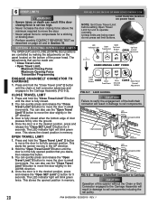
... Force Control Adjustment ROTATE COUNTER-CLOCKWISE FIG. 6-5 Force Control Adjustment. NOTE: The opener will not close " limit programmed. Repeat as necessary until the green indicator light blinks (about 5 seconds). 2. Adjustment. • If the door does not properly reverse. -
... Force Control Adjustment ROTATE COUNTER-CLOCKWISE FIG. 6-5 Force Control Adjustment. NOTE: The opener will not close " limit programmed. Repeat as necessary until the green indicator light blinks (about 5 seconds). 2. Adjustment. • If the door does not properly reverse. -
Owner's Manual
Page 23
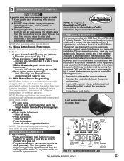
... to operate the same door, nor can learn code button (on a circuit different from the Opener by one or more of Industry Canada. LED Indicator Light Open Open Set Limit Travel Limit Button Up Force OPEN Control Adjustment To Garage Door SET LOST OR STOLEN REMOTE LEARN MANUAL LIMIT FORCE 1. FCC...
... to operate the same door, nor can learn code button (on a circuit different from the Opener by one or more of Industry Canada. LED Indicator Light Open Open Set Limit Travel Limit Button Up Force OPEN Control Adjustment To Garage Door SET LOST OR STOLEN REMOTE LEARN MANUAL LIMIT FORCE 1. FCC...
Owner's Manual
Page 24
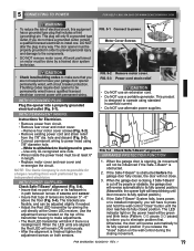
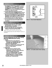
...Remove old battery. • Make sure new battery is needed.) 2. Follow the manufacturer's directions for longer life. • Screw bulb into socket. 2. Light bulb Lens tabs FIG. 9-1 Slide lens onto motor cover. Battery replacement. • To open battery cover. - NOTE: For lens cover locate Box 4....the car visor. • Slide visor clip into place (Fig. 8-3). WARNING For added safety and protection please unplug opener before installing light bulb. Light bulb. • Recommendations. - Do NOT use . • Slip new battery into electrical outlet. Use a heavy duty service bulb ...
...Remove old battery. • Make sure new battery is needed.) 2. Follow the manufacturer's directions for longer life. • Screw bulb into socket. 2. Light bulb Lens tabs FIG. 9-1 Slide lens onto motor cover. Battery replacement. • To open battery cover. - NOTE: For lens cover locate Box 4....the car visor. • Slide visor clip into place (Fig. 8-3). WARNING For added safety and protection please unplug opener before installing light bulb. Light bulb. • Recommendations. - Do NOT use . • Slip new battery into electrical outlet. Use a heavy duty service bulb ...


