

Owner's Manual
Page 1
...® Remote Control Safe-T-Beam® System must be installed to a 7 foot high door. For use only with a Rail Assembly which is standard for up to close door. Homelink® and Car2U® compatible For Answers and Assistance: 1.800.354.3643 or visit www.geniecompany.com SAVE THIS MANUAL FOR FUTURE REFERENCE Car2U® is a registered trademark of Lear Corporation. © The Genie Company...
...® Remote Control Safe-T-Beam® System must be installed to a 7 foot high door. For use only with a Rail Assembly which is standard for up to close door. Homelink® and Car2U® compatible For Answers and Assistance: 1.800.354.3643 or visit www.geniecompany.com SAVE THIS MANUAL FOR FUTURE REFERENCE Car2U® is a registered trademark of Lear Corporation. © The Genie Company...
Owner's Manual
Page 2
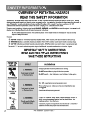
... Turn OFF power before removing operator cover. Since moving parts. Operator must be properly grounded. SAFETY INFORMATION OVERVIEW OF POTENTIAL HAZARDS READ THIS SAFETY INFORMATION Garage doors are large, heavy objects that has a broken spring. WARNING indicates a potentially hazardous situation which door spring parts are fastened, such as, wood blocks, steel brackets, cables or other like items. Installations, repairs and adjustments must be done by a trained door system technician using proper tools and instructions. ELECTRICAL...
... Turn OFF power before removing operator cover. Since moving parts. Operator must be properly grounded. SAFETY INFORMATION OVERVIEW OF POTENTIAL HAZARDS READ THIS SAFETY INFORMATION Garage doors are large, heavy objects that has a broken spring. WARNING indicates a potentially hazardous situation which door spring parts are fastened, such as, wood blocks, steel brackets, cables or other like items. Installations, repairs and adjustments must be done by a trained door system technician using proper tools and instructions. ELECTRICAL...
Owner's Manual
Page 3
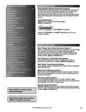
.... Use during a power failure or other emergency to close door. An access code copied from door opener. Manual Emergency Release. Turns ON when door is detected. Follow the Homelink® or Car2U® instructions in your car owner's manual. TABLE OF CONTENTS SECTION PAGE SAFETY INFORMATION 2 OPENER FEATURES 3 SAFETY FEATURES 3 PRE-INSTALLATION CHECK LIST 4-5 RECOMMENDED TOOLS 6 PARTS IDENTIFICATION 6-7 KEY ILLUSTRATIONS 8 SAFETY INSTALLATION INFORMATION 9 INSTALLATION 1 OPENER ASSEMBLY 9-11 2 INSTALLATION 12-14 3 WALL BUTTON INSTALLATION 15-16 4 SAFE-T-BEAM®...
.... Use during a power failure or other emergency to close door. An access code copied from door opener. Manual Emergency Release. Turns ON when door is detected. Follow the Homelink® or Car2U® instructions in your car owner's manual. TABLE OF CONTENTS SECTION PAGE SAFETY INFORMATION 2 OPENER FEATURES 3 SAFETY FEATURES 3 PRE-INSTALLATION CHECK LIST 4-5 RECOMMENDED TOOLS 6 PARTS IDENTIFICATION 6-7 KEY ILLUSTRATIONS 8 SAFETY INSTALLATION INFORMATION 9 INSTALLATION 1 OPENER ASSEMBLY 9-11 2 INSTALLATION 12-14 3 WALL BUTTON INSTALLATION 15-16 4 SAFE-T-BEAM®...
Owner's Manual
Page 4
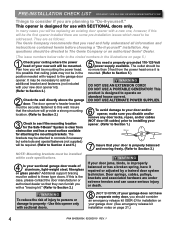
... installed within code specifications. 4 Is your new unit will be replacing an existing door opener with SECTIONAL doors only. This product is designed for installation on your garage door. (See emergency release kit installation notes on page 5.) 1 Check your ceiling where the power head of your sectional garage door made of injury to persons or damage to property - It is mounted. (Refer to Section 5.) WARNING DO NOT USE AN EXTENSION CORD! PRE-INSTALLATION...
... installed within code specifications. 4 Is your new unit will be replacing an existing door opener with SECTIONAL doors only. This product is designed for installation on your garage door. (See emergency release kit installation notes on page 5.) 1 Check your ceiling where the power head of your sectional garage door made of injury to persons or damage to property - It is mounted. (Refer to Section 5.) WARNING DO NOT USE AN EXTENSION CORD! PRE-INSTALLATION...
Owner's Manual
Page 6
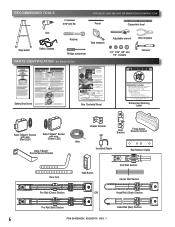
... Remote Control Safe-T-Beam® Source/Sensor Bracket Insulated Staple Rail Section Clamp Door Arm Wall Button End Rail Section Center Rail Section Pro Rail (Chain) Section OR Head Rail (Chain) Section Pro Rail (Belt) Section Head Rail (Belt) Section 6 PN# 3642036534, 02/26/2010 REV. 1 Arrange three small boxes for assembly steps. Remove rail sections not connected to reverse door, repair or replace opener. Arrange rails in sight. • If person is pinned, push control button or use emergency release. • Test door opener monthly: Refer Place to 11/ your' owner...
... Remote Control Safe-T-Beam® Source/Sensor Bracket Insulated Staple Rail Section Clamp Door Arm Wall Button End Rail Section Center Rail Section Pro Rail (Chain) Section OR Head Rail (Chain) Section Pro Rail (Belt) Section Head Rail (Belt) Section 6 PN# 3642036534, 02/26/2010 REV. 1 Arrange three small boxes for assembly steps. Remove rail sections not connected to reverse door, repair or replace opener. Arrange rails in sight. • If person is pinned, push control button or use emergency release. • Test door opener monthly: Refer Place to 11/ your' owner...
Owner's Manual
Page 7
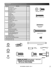
...''-18 LAG SCREW - 5/16'' x 2'' 4 SELF DRILLING SCREW - 1/4''-20 x 3/4'' DOOR BRACKET 5 HEX BOLT - 5/16''-18 x 3/4'' SELF LOCKING NUT - 5/16''-18 HEX FLANGE NUT - 5/16''-18 CLEVIS PIN - 5/16" x 3/4" COTTER PIN 6 WALL BUTTON BUTTON ASSEMBLY PAN HEAD PHILLIPS SCREW - #4-24 x 1'' 7 13 MM INSULATED STAPLE 8 Safe-T-Beam® SOURCE/SENSOR BRACKET PHILLIPS HEX SCREW - #10-16 x 1- 1/4'' WIRE NUT (GREY) NO NUMBER REMOTE WITH BATTERY NO BAG Safe-T-Beam® SOURCE/SENSOR & WIRE SET NO NUMBER LIGHT COVER - Information needed when calling • Model number - (located on...
...''-18 LAG SCREW - 5/16'' x 2'' 4 SELF DRILLING SCREW - 1/4''-20 x 3/4'' DOOR BRACKET 5 HEX BOLT - 5/16''-18 x 3/4'' SELF LOCKING NUT - 5/16''-18 HEX FLANGE NUT - 5/16''-18 CLEVIS PIN - 5/16" x 3/4" COTTER PIN 6 WALL BUTTON BUTTON ASSEMBLY PAN HEAD PHILLIPS SCREW - #4-24 x 1'' 7 13 MM INSULATED STAPLE 8 Safe-T-Beam® SOURCE/SENSOR BRACKET PHILLIPS HEX SCREW - #10-16 x 1- 1/4'' WIRE NUT (GREY) NO NUMBER REMOTE WITH BATTERY NO BAG Safe-T-Beam® SOURCE/SENSOR & WIRE SET NO NUMBER LIGHT COVER - Information needed when calling • Model number - (located on...

Owner's Manual
Page 9
...: Three (3) piece rail assemblies are for assembly. 1. For quick reference inside . 2. Remove box #4 and place it on the floor. 1 OPENER ASSEMBLY RAIL ASSEMBLY: Use a clean, flat surface. Install the Emergency Release Tag on the floor for later use . READ AND FOLLOW ALL SAFETY, INSTALLATION AND OPERATION INSTRUCTIONS. (If you have questions or do so. Remove all ropes and remove or make repairs or adjustments to cables, spring assemblies, and other hardware before installing opener. 4. FOR HELP...
...: Three (3) piece rail assemblies are for assembly. 1. For quick reference inside . 2. Remove box #4 and place it on the floor. 1 OPENER ASSEMBLY RAIL ASSEMBLY: Use a clean, flat surface. Install the Emergency Release Tag on the floor for later use . READ AND FOLLOW ALL SAFETY, INSTALLATION AND OPERATION INSTRUCTIONS. (If you have questions or do so. Remove all ropes and remove or make repairs or adjustments to cables, spring assemblies, and other hardware before installing opener. 4. FOR HELP...
Owner's Manual
Page 11
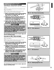
... motor shaft. Use (3) bolts, 5/16"-18 x 1/2" (Fig. 1-5). 2. Tighten belt until chain is located in the Belt Pulley Bracket (opposite rail end from the power head) (Fig. 1-6). 3. If you have not, remove all ropes and/or cables (NOT door lift cables) and disabled the door lock already. CAUTION You should have removed all ropes and/or cables and disable garage door lock NOW before continuing with Section 2 INSTALLATION. Power head assembly. Belt Pulley Bracket (at wall...
... motor shaft. Use (3) bolts, 5/16"-18 x 1/2" (Fig. 1-5). 2. Tighten belt until chain is located in the Belt Pulley Bracket (opposite rail end from the power head) (Fig. 1-6). 3. If you have not, remove all ropes and/or cables (NOT door lift cables) and disabled the door lock already. CAUTION You should have removed all ropes and/or cables and disable garage door lock NOW before continuing with Section 2 INSTALLATION. Power head assembly. Belt Pulley Bracket (at wall...
Owner's Manual
Page 13
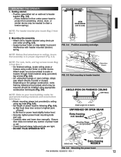
... header bracket pins locate Bag 2 from Box 1. • On finished ceilings, locate ceiling joists or trusses using appropriate construction techniques (Fig. 2-6). b) Be level or power head slightly below level. • Securely tighten power head mounting bolts and nuts. • Carefully raise and lower door manually. Mounting the assembly. • Attach rail to header bracket using lag bolts (Fig. 2-6). • Set height of travel. Depending on wall next to beams UNFINISHED OR OPEN BEAM...
... header bracket pins locate Bag 2 from Box 1. • On finished ceilings, locate ceiling joists or trusses using appropriate construction techniques (Fig. 2-6). b) Be level or power head slightly below level. • Securely tighten power head mounting bolts and nuts. • Carefully raise and lower door manually. Mounting the assembly. • Attach rail to header bracket using lag bolts (Fig. 2-6). • Set height of travel. Depending on wall next to beams UNFINISHED OR OPEN BEAM...
Owner's Manual
Page 15
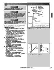
.... 3-2). • Fasten wire to control board screws on back of wall button button. - White wire to the - (minus) terminal. This is NO power to the + (plus ) terminal. - WARNING Use of wire routing when NOT pre-wired. Striped wire to the opener before installing wall button wires and wall button. NOTE: For Wall Button, wire and insulated staples locate Bags 6 and 7 from power head to wall button board screws on back of door. • It should be at Wall Button.) • Wall Button board screw connections are too...
.... 3-2). • Fasten wire to control board screws on back of wall button button. - White wire to the - (minus) terminal. This is NO power to the + (plus ) terminal. - WARNING Use of wire routing when NOT pre-wired. Striped wire to the opener before installing wall button wires and wall button. NOTE: For Wall Button, wire and insulated staples locate Bags 6 and 7 from power head to wall button board screws on back of door. • It should be at Wall Button.) • Wall Button board screw connections are too...
Owner's Manual
Page 17
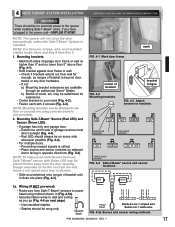
... opener while installing Safe-T-Beam® wires. Source Sensor • Route wire from Safe-T-Beam® sensors to wall and ceiling as you have plugged in (Fig. 4-5a). • Securely fasten wires to power head using concrete anchors (not provided). 2. PN# 3642036534, 02/26/2010 REV. 1 17 Mounting brackets. • Mark both sides of bracket until it will not close the door automatically unless the Safe-T-Beam® System is installed. Mounting Safe-T-Beam® Source (Red LED) and Sensor (Green LED...
... opener while installing Safe-T-Beam® wires. Source Sensor • Route wire from Safe-T-Beam® sensors to wall and ceiling as you have plugged in (Fig. 4-5a). • Securely fasten wires to power head using concrete anchors (not provided). 2. PN# 3642036534, 02/26/2010 REV. 1 17 Mounting brackets. • Mark both sides of bracket until it will not close the door automatically unless the Safe-T-Beam® System is installed. Mounting Safe-T-Beam® Source (Red LED) and Sensor (Green LED...
Owner's Manual
Page 19
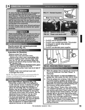
... use alternate power supplies. This product is designed to green. - WITH PERMANENT WIRING: Instructions for charges resulting from the 7/8" dia. When the LED units are flexible, and can be at the Green LED receiver. When the garage door is closing movement. Motor Cover Screws CAUTION • Check local building codes to install one. FIG. 5-2 Remove motor cover. FIG. 5-3 Power cord strain relief. If the Safe-T-Beam® System fails, loses power, or is installed improperly, you release...
... use alternate power supplies. This product is designed to green. - WITH PERMANENT WIRING: Instructions for charges resulting from the 7/8" dia. When the LED units are flexible, and can be at the Green LED receiver. When the garage door is closing movement. Motor Cover Screws CAUTION • Check local building codes to install one. FIG. 5-2 Remove motor cover. FIG. 5-3 Power cord strain relief. If the Safe-T-Beam® System fails, loses power, or is installed improperly, you release...
Owner's Manual
Page 20
... 10. LED Indicator Light Open Open Set Limit Travel Limit Button Up Force OPEN Control Adjustment To Garage Door SET LEARN MANUAL LIMIT FORCE SET Learn Code CODE Button Close Travel Limit Close CLOSE Down Force Set Limit Control Button Adjustment FIG. 6-1 Limit controls. 6 DOOR LIMITS WARNING • Severe injury or death can quickly press and release the "Close Travel Limit" button to move the door in small increments. The adjustments that you desire, then release this direction Latch Movement Carriage Assembly Chain Connector Move in memory. CLOSE TRAVEL LIMIT...
... 10. LED Indicator Light Open Open Set Limit Travel Limit Button Up Force OPEN Control Adjustment To Garage Door SET LEARN MANUAL LIMIT FORCE SET Learn Code CODE Button Close Travel Limit Close CLOSE Down Force Set Limit Control Button Adjustment FIG. 6-1 Limit controls. 6 DOOR LIMITS WARNING • Severe injury or death can quickly press and release the "Close Travel Limit" button to move the door in small increments. The adjustments that you desire, then release this direction Latch Movement Carriage Assembly Chain Connector Move in memory. CLOSE TRAVEL LIMIT...
Owner's Manual
Page 22
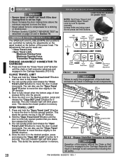
... FIG. 6-5 Force Control Adjustment. Repeat as necessary until the green indicator light blinks (about 5 seconds). 2. Set the DOWN force level at the minimum force required to open travel limit settings are erased. Once the desired level is installed. NOTE: The opener will not close " limit before testing. 1. Place a 2" x 4" board (laid flat) under center of door opening (Fig. 6-6). • Close door using wall button. - It should not have reached its "close the door automatically unless the Safe-T-Beam® System...
... FIG. 6-5 Force Control Adjustment. Repeat as necessary until the green indicator light blinks (about 5 seconds). 2. Set the DOWN force level at the minimum force required to open travel limit settings are erased. Once the desired level is installed. NOTE: The opener will not close " limit before testing. 1. Place a 2" x 4" board (laid flat) under center of door opening (Fig. 6-6). • Close door using wall button. - It should not have reached its "close the door automatically unless the Safe-T-Beam® System...
Owner's Manual
Page 23
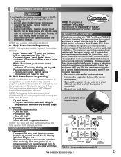
...with the limits for use with FCC Part 15 and RSS 210 of the FCC Rules. LEARN • Locate "Learn Code" button and indicator CODE LED on power head. Program each button. - These limits are designed to radio or television reception, which has not been reprogrammed. Operating. • Press remote button once. - FCC and IC CERTIFIED This device complies with 1 door. LED Indicator Light Open Open Set Limit Travel Limit Button Up Force OPEN Control Adjustment To Garage Door SET LOST OR STOLEN REMOTE LEARN MANUAL LIMIT FORCE 1. 7 PROGRAMMING REMOTE CONTROLS WARNING...
...with the limits for use with FCC Part 15 and RSS 210 of the FCC Rules. LEARN • Locate "Learn Code" button and indicator CODE LED on power head. Program each button. - These limits are designed to radio or television reception, which has not been reprogrammed. Operating. • Press remote button once. - FCC and IC CERTIFIED This device complies with 1 door. LED Indicator Light Open Open Set Limit Travel Limit Button Up Force OPEN Control Adjustment To Garage Door SET LOST OR STOLEN REMOTE LEARN MANUAL LIMIT FORCE 1. 7 PROGRAMMING REMOTE CONTROLS WARNING...
Owner's Manual
Page 24
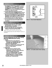
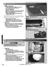
... push straight out on power head with symbols inside battery cover) (Fig. 8-2). - WARNING For added safety and protection please unplug opener before installing light bulb. Use a heavy duty service bulb for battery maintenance, replacement, and use a short neck bulb. - Make sure the tabs are fully engaged into lens slots (Fig. 9-2). • Plug power cord back into back of remote control. - Remove old battery. • Make sure new battery is needed.) 2. Light bulb Lens tabs FIG. 9-1 Slide lens onto motor cover. Battery replacement...
... push straight out on power head with symbols inside battery cover) (Fig. 8-2). - WARNING For added safety and protection please unplug opener before installing light bulb. Use a heavy duty service bulb for battery maintenance, replacement, and use a short neck bulb. - Make sure the tabs are fully engaged into lens slots (Fig. 9-2). • Plug power cord back into back of remote control. - Remove old battery. • Make sure new battery is needed.) 2. Light bulb Lens tabs FIG. 9-1 Slide lens onto motor cover. Battery replacement...

Owner's Manual
Page 25
... ALL INSTRUCTIONS. 2. Door balance. • With the door closed, pull emergency release knob (Carriage Lock) towards door to contact Genie® customer service at the center of garage door opening. • Close door by using remote. - If door moves quickly, CONTACT A TRAINED DOOR SYSTEM TECHNICIAN. • Close the door. • Pull emergency release knob towards the opener to repair or adjust door springs or any questions, please do not hesitate to engage carriage. - Never let children operate or play with opener. Any other wall control...
... ALL INSTRUCTIONS. 2. Door balance. • With the door closed, pull emergency release knob (Carriage Lock) towards door to contact Genie® customer service at the center of garage door opening. • Close door by using remote. - If door moves quickly, CONTACT A TRAINED DOOR SYSTEM TECHNICIAN. • Close the door. • Pull emergency release knob towards the opener to repair or adjust door springs or any questions, please do not hesitate to engage carriage. - Never let children operate or play with opener. Any other wall control...

Owner's Manual
Page 27
... Wall • Program remote control code into outlet used for reversed, broken, or cut insulation and short wires. Noisy operation. • Be sure all remote control codes from • Replace remote control battery (See section 8 ). Place carriage lever in good repair, properly lubricated and balanced (See Maintenance section 10). • Check "OPEN" limit setting (See section 6 ). • Check "OPEN FORCE" adjustment (See section 6 ). • WARNING: If you suspect a problem with the garage door hardware or springs, contact an authorized Genie...
... Wall • Program remote control code into outlet used for reversed, broken, or cut insulation and short wires. Noisy operation. • Be sure all remote control codes from • Replace remote control battery (See section 8 ). Place carriage lever in good repair, properly lubricated and balanced (See Maintenance section 10). • Check "OPEN" limit setting (See section 6 ). • Check "OPEN FORCE" adjustment (See section 6 ). • WARNING: If you suspect a problem with the garage door hardware or springs, contact an authorized Genie...

Owner's Manual
Page 28
... Safe-T-Beam® sensor • Limits set backwards • Push button wire short 5 BLINKS, Pause (Repeat) • Push button wires reversed in power head connector. (See section 3 ) • Adjust chain/belt tension (See section 1 ). - If the Thermal Protector does not reset. - Contact Genie® authorized dealer for obstruction • Clear limits and reprogram (See section 6 ) • Check push button and wiring. Check door spring - NOTE: The 5 BLINKS pattern will remain blinking until Thermal Protector cools and resets. Contact The Genie...
... Safe-T-Beam® sensor • Limits set backwards • Push button wire short 5 BLINKS, Pause (Repeat) • Push button wires reversed in power head connector. (See section 3 ) • Adjust chain/belt tension (See section 1 ). - If the Thermal Protector does not reset. - Contact Genie® authorized dealer for obstruction • Clear limits and reprogram (See section 6 ) • Check push button and wiring. Check door spring - NOTE: The 5 BLINKS pattern will remain blinking until Thermal Protector cools and resets. Contact The Genie...

Owner's Manual
Page 30
... thereof will be free from the date of purchase and identification as the original purchaser. PARTS - Upon determination by Seller to be made to speak with a trained representative. PURCHASER: INSTALLATION ADDRESS: DATE PURCHASED: OPENER MODEL: REMOTE CONTROL MODEL: DEALER NAME: DEALER ADDRESS: SERIAL NUMBER: P900-775 ModelS 1022/1024/1042 Limited Warranty GMI Holdings, Inc. To obtain warranty service, you . ALL EXPRESS...
... thereof will be free from the date of purchase and identification as the original purchaser. PARTS - Upon determination by Seller to be made to speak with a trained representative. PURCHASER: INSTALLATION ADDRESS: DATE PURCHASED: OPENER MODEL: REMOTE CONTROL MODEL: DEALER NAME: DEALER ADDRESS: SERIAL NUMBER: P900-775 ModelS 1022/1024/1042 Limited Warranty GMI Holdings, Inc. To obtain warranty service, you . ALL EXPRESS...


