User manual
Page 6
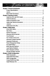
...Expansion Card 12 Install other Internal Connectors 13 Jumpers 17 Install driver and utility 18 Chapter 3 BIOS Setup Enter BIOS Setup 21 Main Menu 21 System Information 23 Advanced BIOS Features 25 Core Releaser 26 Fox Central Control Unit 27 Advanced Chipset Features 32 Integrated Peripherals ...36 Power Management Setup 40 PC Health Status 42 BIOS Security Features 43 Load Optimal Defaults 44 Save Changes and Exit 44 Discard Changes and Exit 44 Chapter 4 RAID Configuration RAID ...
...Expansion Card 12 Install other Internal Connectors 13 Jumpers 17 Install driver and utility 18 Chapter 3 BIOS Setup Enter BIOS Setup 21 Main Menu 21 System Information 23 Advanced BIOS Features 25 Core Releaser 26 Fox Central Control Unit 27 Advanced Chipset Features 32 Integrated Peripherals ...36 Power Management Setup 40 PC Health Status 42 BIOS Security Features 43 Load Optimal Defaults 44 Save Changes and Exit 44 Discard Changes and Exit 44 Chapter 4 RAID Configuration RAID ...
User manual
Page 17
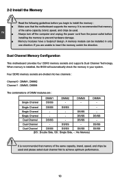
.... CAUTION 10 When memory is recommended that memory of the same capacity, brand, speed, and chips be installed in your system. It is installed, the BIOS will automatically check the memory in only one direction.
.... CAUTION 10 When memory is recommended that memory of the same capacity, brand, speed, and chips be installed in your system. It is installed, the BIOS will automatically check the memory in only one direction.
User manual
Page 19
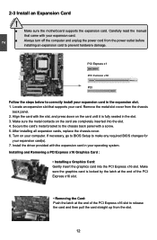
... the steps below to release the card and then pull the card straight up from the chassis back panel. 2. If necessary, go to BIOS Setup to make any required BIOS changes for your computer. 2 CAUTION 2-3 Install an Expansion Card ! ■ Make sure the motherboard supports the expansion card. Make sure the metal...
... the steps below to release the card and then pull the card straight up from the chassis back panel. 2. If necessary, go to BIOS Setup to make any required BIOS changes for your computer. 2 CAUTION 2-3 Install an Expansion Card ! ■ Make sure the motherboard supports the expansion card. Make sure the metal...
User manual
Page 23
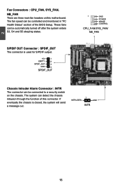
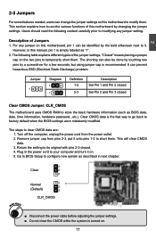
... 4 SPDIF_OUT 1 GND POWER SENSE CONTROL CPU_FAN/SYS_FAN/ NB_FAN Chassis Intruder Alarm Connector : INTR The connector can detect the chassis intrusion through the function of the BIOS Setup. S/PDIF OUT Connector : SPDIF_OUT The connector is closed, the system will send a message out. 1 INTRUDERJ GND INTR 16 These fans can be automatically turned...
... 4 SPDIF_OUT 1 GND POWER SENSE CONTROL CPU_FAN/SYS_FAN/ NB_FAN Chassis Intruder Alarm Connector : INTR The connector can detect the chassis intrusion through the function of the BIOS Setup. S/PDIF OUT Connector : SPDIF_OUT The connector is closed, the system will send a message out. 1 INTRUDERJ GND INTR 16 These fans can be automatically turned...
User manual
Page 24
... next to your computer and turn it . "Closed" means placing a jumper cap on . 5. Remove jumper cap from the power outlet. 2. Go to BIOS Setup to modifying any jumper on this motherboard, pin 1 can be done by touching two pins by a screwdriver for a few seconds, but using jumper cap...the power cord to it on the two pins to store the basic hardware information (such as BIOS data, date, time information, hardware password...etc.). The steps to factory default when the BIOS settings were mistakenly modified. Return the setting to its original with pins 2-3 closed Clear...
... next to your computer and turn it . "Closed" means placing a jumper cap on . 5. Remove jumper cap from the power outlet. 2. Go to BIOS Setup to modifying any jumper on this motherboard, pin 1 can be done by touching two pins by a screwdriver for a few seconds, but using jumper cap...the power cord to it on the two pins to store the basic hardware information (such as BIOS data, date, time information, hardware password...etc.). The steps to factory default when the BIOS settings were mistakenly modified. Return the setting to its original with pins 2-3 closed Clear...
User manual
Page 27
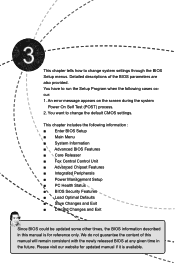
...This chapter includes the following cases occur: 1. We do not guarantee the content of the BIOS parameters are also provided. You have to change system settings through the BIOS Setup menus. Please visit our website for updated manual if it is for reference only. ... Test (POST) process. 2. You want to run the Setup Program when the following information : ■ Enter BIOS Setup ■ Main Menu ■ System Information ■ Advanced BIOS Features ■ Core Releaser ■ Fox Central Control Unit ■ Advanced Chipset Features ■ Integrated Peripherals &#...
...This chapter includes the following cases occur: 1. We do not guarantee the content of the BIOS parameters are also provided. You have to change system settings through the BIOS Setup menus. Please visit our website for updated manual if it is for reference only. ... Test (POST) process. 2. You want to run the Setup Program when the following information : ■ Enter BIOS Setup ■ Main Menu ■ System Information ■ Advanced BIOS Features ■ Core Releaser ■ Fox Central Control Unit ■ Advanced Chipset Features ■ Integrated Peripherals &#...
User manual
Page 28
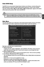
... Name, memory size plus system date, time and Floppy drive. They all can be viewed or set up through this menu. ► Advanced BIOS Features The advanced system features can be set up settings. ► Core Releaser (Enabled only if CPU supports) The Core Releaser function can be.... 21 When the message "Press to Setup Core Releaser, " appears at the bottom of setup functions together with two exit choices. Enter BIOS Setup The BIOS is the communication bridge between hardware and software, correctly setting up through this menu. Use the arrow keys to select a specific item and ...
... Name, memory size plus system date, time and Floppy drive. They all can be viewed or set up through this menu. ► Advanced BIOS Features The advanced system features can be set up settings. ► Core Releaser (Enabled only if CPU supports) The Core Releaser function can be.... 21 When the message "Press to Setup Core Releaser, " appears at the bottom of setup functions together with two exit choices. Enter BIOS Setup The BIOS is the communication bridge between hardware and software, correctly setting up through this menu. Use the arrow keys to select a specific item and ...
User manual
Page 29
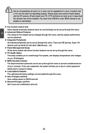
... a password, the system will ask you to read/change Fan speeds, and displays temperatures and voltages of your PC. You need clear CMOS or enter BIOS manual to set up through this menu to 4 cores. If PC still does not work at all used 2 or 3 cores can be set disable to... the system performance can be optimized. ► Integrated Peripherals All onboard peripherals can not be upgraded to prevent unauthorized use of your CPU/System. ► BIOS Security Features The Supervisor/User password can be enabled.
... a password, the system will ask you to read/change Fan speeds, and displays temperatures and voltages of your PC. You need clear CMOS or enter BIOS manual to set up through this menu to 4 cores. If PC still does not work at all used 2 or 3 cores can be set disable to... the system performance can be optimized. ► Integrated Peripherals All onboard peripherals can not be upgraded to prevent unauthorized use of your CPU/System. ► BIOS Security Features The Supervisor/User password can be enabled.
User manual
Page 30
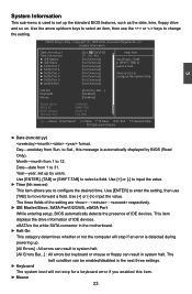
... [+] or [-] to [Not Detected] configure the system Date. [Not Detected] [Not Detected] Halt On Keyboard Mouse [All Errors, But ...] [Disabled] [Disabled] Model Name BIOS ID BIOS Version Memory Size :A88GMV :A34F1P01 :08.00.16 :1024MB Move Enter:Select +/-/:Value F10:Save ESC:Exit F1:General Help F9:Optimized Defaults 3 ► Date (mm:dd...
... [+] or [-] to [Not Detected] configure the system Date. [Not Detected] [Not Detected] Halt On Keyboard Mouse [All Errors, But ...] [Disabled] [Disabled] Model Name BIOS ID BIOS Version Memory Size :A88GMV :A34F1P01 :08.00.16 :1024MB Move Enter:Select +/-/:Value F10:Save ESC:Exit F1:General Help F9:Optimized Defaults 3 ► Date (mm:dd...

User manual
Page 31
3 The system boot will not stop for a mouse error if you enabled this item. ► Model Name Model name of this information and discuss with the field service people if a BIOS upgrade is depending on how many memory modules were installed in your system before powering on. ► MAC Address This item shows the onboard LAN MAC address. ► CPU Name It displays the current CPU name. 24 The size is needed. ► Memory Size This item displays the current memory size. User can check this product. ► BIOS ID / BIOS Version It displays the current BIOS ID/version.
3 The system boot will not stop for a mouse error if you enabled this item. ► Model Name Model name of this information and discuss with the field service people if a BIOS upgrade is depending on how many memory modules were installed in your system before powering on. ► MAC Address This item shows the onboard LAN MAC address. ► CPU Name It displays the current CPU name. 24 The size is needed. ► Memory Size This item displays the current memory size. User can check this product. ► BIOS ID / BIOS Version It displays the current BIOS ID/version.
User manual
Page 32
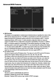
...This feature controls how long each PCI device to the disadvantage of other devices on a motherboard that the motherboard will have to set . Advanced BIOS Features MPS Revision PCI Latency Timer Quiet Boot Quick Boot Bootup Num-Lock [1.4] Help Item [64] [Enabled] Select MPS Revision [Enabled] [On... PCI device can hold the bus before they can get access to make use . Copyright (C) 1985-2006, American Megatrends, Inc. Advanced BIOS Features CMOS Setup Utility - Higher values will actually reduce performance as 1.1 only if you need to the bus, but when they do ...
...This feature controls how long each PCI device to the disadvantage of other devices on a motherboard that the motherboard will have to set . Advanced BIOS Features MPS Revision PCI Latency Timer Quiet Boot Quick Boot Bootup Num-Lock [1.4] Help Item [64] [Enabled] Select MPS Revision [Enabled] [On... PCI device can hold the bus before they can get access to make use . Copyright (C) 1985-2006, American Megatrends, Inc. Advanced BIOS Features CMOS Setup Utility - Higher values will actually reduce performance as 1.1 only if you need to the bus, but when they do ...
User manual
Page 33
Copyright (C) 1985-2006, American Megatrends, Inc. 3 ► Quick Boot While Enabled, this option allows BIOS to skip certain tests while booting, this will shorten the time needed to boot the system. ► Bootup Num-Lock This item defines if the ...
Copyright (C) 1985-2006, American Megatrends, Inc. 3 ► Quick Boot While Enabled, this option allows BIOS to skip certain tests while booting, this will shorten the time needed to boot the system. ► Bootup Num-Lock This item defines if the ...
User manual
Page 34
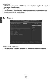
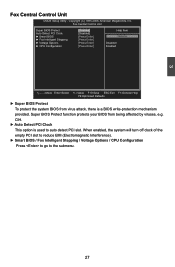
...Megatrends, Inc. CIH. ► Auto Detect PCI Clock This option is a BIOS write-protection mechanism provided. 3 Fox Central Control Unit CMOS Setup Utility - Super BIOS Protect function protects your BIOS from virus attack, there is used to the submenu. 27 When enabled, the... Stepping / Voltage Options / CPU Configuration Press to go to auto detect PCI slot. Fox Central Control Unit Super BIOS Protect Auto Detect PCI Clock ► Smart BIOS ► Fox Intelligent Stepping ► Voltage Options ► CPU Configuration [Disabled] Help Item [Disabled] [Press ...
...Megatrends, Inc. CIH. ► Auto Detect PCI Clock This option is a BIOS write-protection mechanism provided. 3 Fox Central Control Unit CMOS Setup Utility - Super BIOS Protect function protects your BIOS from virus attack, there is used to the submenu. 27 When enabled, the... Stepping / Voltage Options / CPU Configuration Press to go to auto detect PCI slot. Fox Central Control Unit Super BIOS Protect Auto Detect PCI Clock ► Smart BIOS ► Fox Intelligent Stepping ► Voltage Options ► CPU Configuration [Disabled] Help Item [Disabled] [Press ...
User manual
Page 35
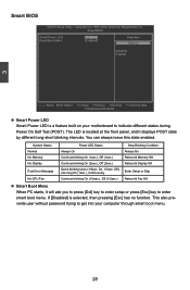
Smart BIOS Smart Power LED Smart Boot Menu [Enabled] [Enabled] Help Item Options Disabled Enabled Move Enter:Select +/-/:Value F10:Save ESC:Exit F1:General Help F9:... Enter Setup or Skip Reboot & Fan OK ► Smart Boot Menu When PC starts, it displays POST state by different long-short blinking intervals. 3 Smart BIOS CMOS Setup Utility - The LED is selected, then pressing [Esc] has no function. System Status Normal No Memory No Display Post Error Message No CPU...
Smart BIOS Smart Power LED Smart Boot Menu [Enabled] [Enabled] Help Item Options Disabled Enabled Move Enter:Select +/-/:Value F10:Save ESC:Exit F1:General Help F9:... Enter Setup or Skip Reboot & Fan OK ► Smart Boot Menu When PC starts, it displays POST state by different long-short blinking intervals. 3 Smart BIOS CMOS Setup Utility - The LED is selected, then pressing [Esc] has no function. System Status Normal No Memory No Display Post Error Message No CPU...
User manual
Page 39
... display the values configured at the settings of clock cycles that elapse from the time the request for the integrated graphics controller from within the BIOS. 32 The CAS Latency is the number of "DRAM Timing Mode". ► CAS Latency This item shows the CAS latency.
... display the values configured at the settings of clock cycles that elapse from the time the request for the integrated graphics controller from within the BIOS. 32 The CAS Latency is the number of "DRAM Timing Mode". ► CAS Latency This item shows the CAS latency.
User manual
Page 40
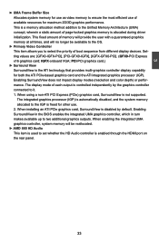
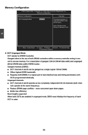
... provides multi-graphics controller display capability for both the ATI PCIe-based graphics card and the ATI integrated graphics processor (IGP). Enabling SurroundView in the BIOS enables the integrated UMA graphics controller, which in turn makes available up to two additional graphics outputs. When enabling the integrated UMA graphics controller, system...
... provides multi-graphics controller display capability for both the ATI PCIe-based graphics card and the ATI integrated graphics processor (IGP). Enabling SurroundView in the BIOS enables the integrated UMA graphics controller, which in turn makes available up to two additional graphics outputs. When enabling the integrated UMA graphics controller, system...
User manual
Page 41
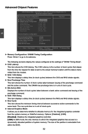
...; Offers highest DDR2 bandwidth. ■ Requires both DIMMs in a logical pair to have identical size and timing parameters, both DCTs are enabled in unganged mode, BIOS must initialize the frequency of each DCT in concert to the use of unganged DRAM mode 64-bit width Auto= Ganged mode Always=Unganged mode...
...; Offers highest DDR2 bandwidth. ■ Requires both DIMMs in a logical pair to have identical size and timing parameters, both DCTs are enabled in unganged mode, BIOS must initialize the frequency of each DCT in concert to the use of unganged DRAM mode 64-bit width Auto= Ganged mode Always=Unganged mode...
User manual
Page 42
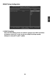
... Help F9:Optimized Defaults ► DRAM Timing Mode When both DCTs (DRAM controller) are : [Auto], [DCT 0], [DCT 1], [Both]. 35 Settings are enabled in unganged mode, BIOS must initialize the frequency of each DCT in order, you also can configure the timings manually. 3 DRAM Timing Configuration CMOS Setup Utility -
... Help F9:Optimized Defaults ► DRAM Timing Mode When both DCTs (DRAM controller) are : [Auto], [DCT 0], [DCT 1], [Both]. 35 Settings are enabled in unganged mode, BIOS must initialize the frequency of each DCT in order, you also can configure the timings manually. 3 DRAM Timing Configuration CMOS Setup Utility -
User manual
Page 45
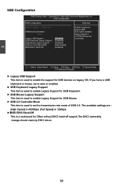
USB Keyboard Legacy Support [Enabled] USB Mouse Legacy Support [Enabled] USB 2.0 Controller Mode [High Speed] BIOS EHCI Hand-Off [Enabled] Move Enter:Select +/-/:Value F10:Save ESC:Exit F1:General Help F9:Optimized Defaults ► Legacy USB ... Devices Enabled : Auto option disables None legacy support if no USB devices are : [High Speed] in 480Mbps; [Full Speed] in 12Mbps. ►BIOS EHCI Hand-Off This is used to enable the support for USB devices on legacy OS. USB Configuration USB Configuration Help Item Module Version - 2.24...
USB Keyboard Legacy Support [Enabled] USB Mouse Legacy Support [Enabled] USB 2.0 Controller Mode [High Speed] BIOS EHCI Hand-Off [Enabled] Move Enter:Select +/-/:Value F10:Save ESC:Exit F1:General Help F9:Optimized Defaults ► Legacy USB ... Devices Enabled : Auto option disables None legacy support if no USB devices are : [High Speed] in 480Mbps; [Full Speed] in 12Mbps. ►BIOS EHCI Hand-Off This is used to enable the support for USB devices on legacy OS. USB Configuration USB Configuration Help Item Module Version - 2.24...
User manual
Page 46
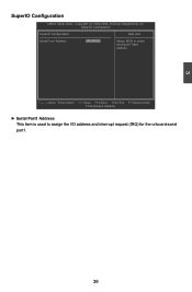
3 SuperIO Configuration CMOS Setup Utility - Move Enter:Select +/-/:Value F10:Save ESC:Exit F1:General Help F9:Optimized Defaults ► Serial Port1 Address This item is used to select serial port1 base address. Copyright (C) 1985-2006, American Megatrends, Inc. SuperIO Configuration SuperIO Configuration Help Item Serial Port1 Address [3F8/IRQ 4] Allows BIOS to assign the I/O address and interrupt request (IRQ) for the onboard serial port1. 39
3 SuperIO Configuration CMOS Setup Utility - Move Enter:Select +/-/:Value F10:Save ESC:Exit F1:General Help F9:Optimized Defaults ► Serial Port1 Address This item is used to select serial port1 base address. Copyright (C) 1985-2006, American Megatrends, Inc. SuperIO Configuration SuperIO Configuration Help Item Serial Port1 Address [3F8/IRQ 4] Allows BIOS to assign the I/O address and interrupt request (IRQ) for the onboard serial port1. 39


