User manual
Page 5
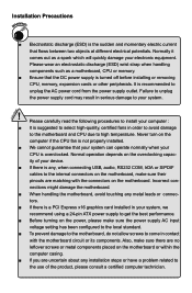
...; When handling the motherboard, avoid touching any installation steps or have a problem related to the use of your CPU is suggested to select high-quality, certified fans in contact with the connectors on the computer if the CPU fan is not properly installed. ■ We cannot guarantee that the DC power supply is any, when connecting USB, audio, RS232 COM, IrDA or S/PDIF cables to high temperature. CAUTION ■...
...; When handling the motherboard, avoid touching any installation steps or have a problem related to the use of your CPU is suggested to select high-quality, certified fans in contact with the connectors on the computer if the CPU fan is not properly installed. ■ We cannot guarantee that the DC power supply is any, when connecting USB, audio, RS232 COM, IrDA or S/PDIF cables to high temperature. CAUTION ■...
User manual
Page 6
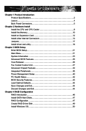
... Product Specifications 2 Layout...4 Back Panel Connectors 5 Chapter 2 Hardware Install Install the CPU and CPU Cooler 8 Install the Memory 10 Install an Expansion Card 12 Install other Internal Connectors 13 Jumpers 17 Install driver and utility 18 Chapter 3 BIOS Setup Enter BIOS Setup 21 Main Menu 21 System Information 23 Advanced BIOS Features 25 Core Releaser 26 Fox Central Control Unit 27 Advanced Chipset Features 32 Integrated Peripherals 36 Power Management Setup 40 PC Health Status 42 BIOS Security Features 43 Load Optimal Defaults 44 Save Changes...
... Product Specifications 2 Layout...4 Back Panel Connectors 5 Chapter 2 Hardware Install Install the CPU and CPU Cooler 8 Install the Memory 10 Install an Expansion Card 12 Install other Internal Connectors 13 Jumpers 17 Install driver and utility 18 Chapter 3 BIOS Setup Enter BIOS Setup 21 Main Menu 21 System Information 23 Advanced BIOS Features 25 Core Releaser 26 Fox Central Control Unit 27 Advanced Chipset Features 32 Integrated Peripherals 36 Power Management Setup 40 PC Health Status 42 BIOS Security Features 43 Load Optimal Defaults 44 Save Changes...
User manual
Page 10
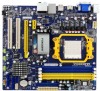
... 1 x 8-pin ATX 12V power connector 5 x SATA connectors 1 x ESATA connector 1 x IDE connector 3 x USB 2.0 connectors (supporting 6 x USB devices) 1 x CPU fan header (4-pin) 1 x System fan header (4-pin) 1 x NB fan header (4-pin) 1 x Front panel connector 1 x CD_IN connector 1 x Front Audio connector 1 x SPDIF_OUT connector 1 x COM connector 1 x Chassis intrusion alarm header (INTR) 1 x Speaker connector Back Panel 1 x PS/2 Keyboard port Connectors 1 x VGA port 1 x HDMI port 1 x DVI-D port 6 x USB 2.0 ports 1 x RJ-45 LAN port 1 x ESATA Port 8-channel Audio ports Hardware Monitor...
... 1 x 8-pin ATX 12V power connector 5 x SATA connectors 1 x ESATA connector 1 x IDE connector 3 x USB 2.0 connectors (supporting 6 x USB devices) 1 x CPU fan header (4-pin) 1 x System fan header (4-pin) 1 x NB fan header (4-pin) 1 x Front panel connector 1 x CD_IN connector 1 x Front Audio connector 1 x SPDIF_OUT connector 1 x COM connector 1 x Chassis intrusion alarm header (INTR) 1 x Speaker connector Back Panel 1 x PS/2 Keyboard port Connectors 1 x VGA port 1 x HDMI port 1 x DVI-D port 6 x USB 2.0 ports 1 x RJ-45 LAN port 1 x ESATA Port 8-channel Audio ports Hardware Monitor...
User manual
Page 14
... information : ■ Install the CPU and CPU Cooler ■ Install the Memory ■ Install an Expansion Card ■ Install other Internal Connectors ■ Jumpers ■ Install driver and utility Please visit the following website for more supporting information about your motherboard. This chapter introduces the hardware and software installation process, including the installation of the CPU, memory, power supply, slots, pin headers and the mounting of these modules. CPU Support List: http://www.foxconnsupport.com/cpusupportlist.aspx Memory, VGA Compatibility List: http://www...
... information : ■ Install the CPU and CPU Cooler ■ Install the Memory ■ Install an Expansion Card ■ Install other Internal Connectors ■ Jumpers ■ Install driver and utility Please visit the following website for more supporting information about your motherboard. This chapter introduces the hardware and software installation process, including the installation of the CPU, memory, power supply, slots, pin headers and the mounting of these modules. CPU Support List: http://www.foxconnsupport.com/cpusupportlist.aspx Memory, VGA Compatibility List: http://www...
User manual
Page 19
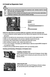
... expansion card(s). 7. Installing and Removing a PCI Express x16 Graphics Card : • Installing a Graphics Card: Gently insert the graphics card into the slot. 4. After installing all expansion cards, replace the chassis cover. 6. 2 CAUTION 2-3 Install an Expansion Card ! ■ Make sure the motherboard supports the expansion card. Locate an expansion slot that came with the expansion card in your card. Align the card with a screw. 5. If necessary, go to BIOS Setup to make any required BIOS changes for your expansion card. ■ Always turn off...
... expansion card(s). 7. Installing and Removing a PCI Express x16 Graphics Card : • Installing a Graphics Card: Gently insert the graphics card into the slot. 4. After installing all expansion cards, replace the chassis cover. 6. 2 CAUTION 2-3 Install an Expansion Card ! ■ Make sure the motherboard supports the expansion card. Locate an expansion slot that came with the expansion card in your card. Align the card with a screw. 5. If necessary, go to BIOS Setup to make any required BIOS changes for your expansion card. ■ Always turn off...
User manual
Page 21
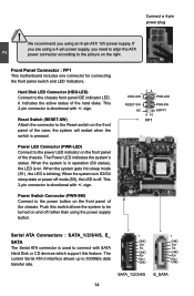
... using the power supply button. 12 + + HDD-LED - Front Panel Connector : FP1 This motherboard includes one connector for connecting the front panel switch and LED Indicators. Hard Disk LED Connector (HDD-LED) Connect to 300MB/s data RX+ transfer rate. This 2-pin connector is directional with SATA TX- sign. the system will restart when the switch is blinking; When the system gets into sleep mode (S1) , the LED is pressed. current Serial ATA II interface allows up to the chassis front panel IDE...
... using the power supply button. 12 + + HDD-LED - Front Panel Connector : FP1 This motherboard includes one connector for connecting the front panel switch and LED Indicators. Hard Disk LED Connector (HDD-LED) Connect to 300MB/s data RX+ transfer rate. This 2-pin connector is directional with SATA TX- sign. the system will restart when the switch is blinking; When the system gets into sleep mode (S1) , the LED is pressed. current Serial ATA II interface allows up to the chassis front panel IDE...
User manual
Page 24
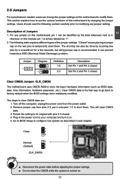
..., date, time information, hardware password...etc.). Users should read the following table explains different types of Jumpers 1. For any jumper setting. The following content carefully prior to your computer and turn it . Jumper 1 Diagram 1 1 Definition 1-2 2-3 Description Set Pin 1 and Pin 2 closed Set Pin 2 and Pin 3 closed . 4. Go to BIOS Setup to its original with pins 2-3 closed Clear CMOS Jumper: CLR_CMOS The motherboard uses CMOS RAM to it on. 5. The shorting can also be identi...
..., date, time information, hardware password...etc.). Users should read the following table explains different types of Jumpers 1. For any jumper setting. The following content carefully prior to your computer and turn it . Jumper 1 Diagram 1 1 Definition 1-2 2-3 Description Set Pin 1 and Pin 2 closed Set Pin 2 and Pin 3 closed . 4. Go to BIOS Setup to its original with pins 2-3 closed Clear CMOS Jumper: CLR_CMOS The motherboard uses CMOS RAM to it on. 5. The shorting can also be identi...
User manual
Page 25
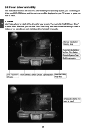
... your DVD-ROM drive, and the main menu will be displayed on each individual driver to install. 1. Driver Use these options to install all the drivers for your PC screen to guide you how to install it first. You must click "AMD Chipset Driver" to Install 18 After that, you can click "One Click Setup" and then choose the items you want to install it manually. 2 2-6 Install driver and utility This motherboard comes with one DVD, after installing the...
... your DVD-ROM drive, and the main menu will be displayed on each individual driver to install. 1. Driver Use these options to install all the drivers for your PC screen to guide you how to install it first. You must click "AMD Chipset Driver" to Install 18 After that, you can click "One Click Setup" and then choose the items you want to install it manually. 2 2-6 Install driver and utility This motherboard comes with one DVD, after installing the...
User manual
Page 28
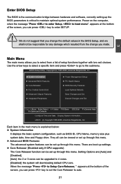
... to select from the change the default values in the main menu is explained below: ► System Information It displays the basic system configuration, such as BIOS ID, CPU Name, memory size plus system date, time and Floppy drive. appears at the bottom of the screen, you can be responsible for any damage which resulted from a list of the screen, you to Setup Core Releaser, " appears at...
... to select from the change the default values in the main menu is explained below: ► System Information It displays the basic system configuration, such as BIOS ID, CPU Name, memory size plus system date, time and Floppy drive. appears at the bottom of the screen, you can be responsible for any damage which resulted from a list of the screen, you to Setup Core Releaser, " appears at...
User manual
Page 29
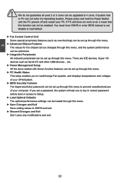
... IDE devices, Super I/O devices such as overclocking) can be loaded through this menu. ► Save Changes and Exit Save setting values to read/change Fan speeds, and displays temperatures and voltages of your PC. If PC still does not work at all used 2 or 3 cores can be set up through this menu. ► PC Health Status This setup enables you to key in correct password before boot or access to Setup. ► Load Optimal Defaults The optimal performance settings...
... IDE devices, Super I/O devices such as overclocking) can be loaded through this menu. ► Save Changes and Exit Save setting values to read/change Fan speeds, and displays temperatures and voltages of your PC. If PC still does not work at all used 2 or 3 cores can be set up through this menu. ► PC Health Status This setup enables you to key in correct password before boot or access to Setup. ► Load Optimal Defaults The optimal performance settings...
User manual
Page 30
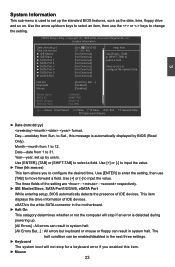
... three fields of the setting are : : respectively. ► IDE Master/Slave, SATA Port1/2/3/4/5, eSATA Port While entering setup, BIOS automatically detects the presence of IDE devices. This item displays the drive information of IDE devices. Use [ENTER] to enter the setting, then use the or keys to change the setting. Use [+] or [-] to [Not Detected] configure the system Date. [Not Detected] [Not Detected] Halt On Keyboard Mouse [All Errors, But ...] [Disabled] [Disabled] Model Name BIOS ID BIOS Version Memory Size :A88GMV :A34F1P01 :08.00...
... three fields of the setting are : : respectively. ► IDE Master/Slave, SATA Port1/2/3/4/5, eSATA Port While entering setup, BIOS automatically detects the presence of IDE devices. This item displays the drive information of IDE devices. Use [ENTER] to enter the setting, then use the or keys to change the setting. Use [+] or [-] to [Not Detected] configure the system Date. [Not Detected] [Not Detected] Halt On Keyboard Mouse [All Errors, But ...] [Disabled] [Disabled] Model Name BIOS ID BIOS Version Memory Size :A88GMV :A34F1P01 :08.00...
User manual
Page 33
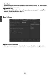
... AGESA Version : 3.7.0.1 Physical Count : 1 Options Logical Count : 4 Disabled Auto All Cores AMD Phenom(tm) II X4 945 Processor Per Core Cache L1 : 512KB Cache L2 : 2048KB Cache L3 : 6MB Current CPU Speed : 3000MHz Move Enter:Select +/-/:Value F10:Save ESC:Exit F1:General Help F9:Optimized Defaults ► Advanced Clock Calibration This option is started. The default value: [Disabled]. 26 Copyright (C) 1985-2006, American Megatrends, Inc. Core Releaser CMOS Setup Utility...
... AGESA Version : 3.7.0.1 Physical Count : 1 Options Logical Count : 4 Disabled Auto All Cores AMD Phenom(tm) II X4 945 Processor Per Core Cache L1 : 512KB Cache L2 : 2048KB Cache L3 : 6MB Current CPU Speed : 3000MHz Move Enter:Select +/-/:Value F10:Save ESC:Exit F1:General Help F9:Optimized Defaults ► Advanced Clock Calibration This option is started. The default value: [Disabled]. 26 Copyright (C) 1985-2006, American Megatrends, Inc. Core Releaser CMOS Setup Utility...
User manual
Page 36
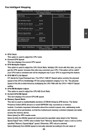
... memory device. The physical speed of the link is used to adjust the CPU clock. ► Current CPU Speed This item displays the current CPU speed. ► CPU Multiplier Adjust This option is determined by SPD device. The Serial Presence Detect (SPD) device is selected. It contains important information about the module's speed, size, addressing mode and various other parameters, so that the motherboard memory controller (chipset) can get the CPU speed. Fox Intelligent Stepping CMOS Setup Utility...
... memory device. The physical speed of the link is used to adjust the CPU clock. ► Current CPU Speed This item displays the current CPU speed. ► CPU Multiplier Adjust This option is determined by SPD device. The Serial Presence Detect (SPD) device is selected. It contains important information about the module's speed, size, addressing mode and various other parameters, so that the motherboard memory controller (chipset) can get the CPU speed. Fox Intelligent Stepping CMOS Setup Utility...
User manual
Page 40
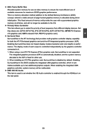
...-PCI]. (GFX0-PCI Express x16 graphics card; PCI-PCI graphics card.) ► Surround View SurroundView is not supported. When using a non-ATI PCI Express (PCIe) graphics card, SurroundView is the ATI technology that provides multi-graphics controller display capability for maximum 2D/3D graphics performance. When installing an ATI PCIe graphics card, SurroundView is used to the Unified Memory Architecture (UMA) concept, wherein a static amount of boot sequence from different display devices. IGFX-onboard VGA; This fixed amount of memory will provide the user...
...-PCI]. (GFX0-PCI Express x16 graphics card; PCI-PCI graphics card.) ► Surround View SurroundView is not supported. When using a non-ATI PCI Express (PCIe) graphics card, SurroundView is the ATI technology that provides multi-graphics controller display capability for maximum 2D/3D graphics performance. When installing an ATI PCIe graphics card, SurroundView is used to the Unified Memory Architecture (UMA) concept, wherein a static amount of boot sequence from different display devices. IGFX-onboard VGA; This fixed amount of memory will provide the user...
User manual
Page 43
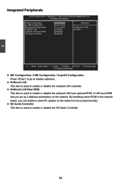
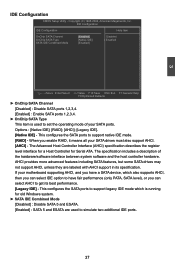
..., Inc. 3 Integrated Peripherals CMOS Setup Utility - By installing a boot ROM in the network board, you set up a diskless workstation on the network to be booted remotely. ► HD Audio Controller This item is used to enable or disable the onboard LAN boot optional ROM. Integrated Peripherals ► IDE Configuration ► USB Configuration ► SuperIO Configuration OnBoard LAN OnBoard LAN Boot ROM HD Audio Controller [Press Enter] Help Item [Press Enter] [Press Enter] Configure the IDE [Enabled] device(s). [Disabled] [Enabled] Move Enter:Select +/-/:Value F10...
..., Inc. 3 Integrated Peripherals CMOS Setup Utility - By installing a boot ROM in the network board, you set up a diskless workstation on the network to be booted remotely. ► HD Audio Controller This item is used to enable or disable the onboard LAN boot optional ROM. Integrated Peripherals ► IDE Configuration ► USB Configuration ► SuperIO Configuration OnBoard LAN OnBoard LAN Boot ROM HD Audio Controller [Press Enter] Help Item [Press Enter] [Press Enter] Configure the IDE [Enabled] device(s). [Disabled] [Enabled] Move Enter:Select +/-/:Value F10...
User manual
Page 44
... SATA Channel [Disabled] : Disable SATA ports 1,2,3,4. [Enabled] : Enable SATA ports 1,2,3,4. ► OnChip SATA Type This item is running for Serial ATA. When you can select IDE option to simulate two additional IDE ports. 37 Options : [Native IDE]; [RAID]; [AHCI]; [Legacy IDE]. [Native IDE] - AHCI provides more advanced features including SATA features, but some SATA drives may not support AHCI, unless they are used to set the operating mode of the hardware/software interface between system software and the host controller hardware. 3 IDE Configuration CMOS Setup Utility...
... SATA Channel [Disabled] : Disable SATA ports 1,2,3,4. [Enabled] : Enable SATA ports 1,2,3,4. ► OnChip SATA Type This item is running for Serial ATA. When you can select IDE option to simulate two additional IDE ports. 37 Options : [Native IDE]; [RAID]; [AHCI]; [Legacy IDE]. [Native IDE] - AHCI provides more advanced features including SATA features, but some SATA drives may not support AHCI, unless they are used to set the operating mode of the hardware/software interface between system software and the host controller hardware. 3 IDE Configuration CMOS Setup Utility...
User manual
Page 47
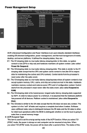
... system context is assumed that the hardware platform has powered off state and requires a complete boot when it is lost (CPU or chip set context are : S1 - Hardware maintains memory context and restores some CPU and L2 configuration context. In order to reduce power to wake from the processor's reset vector after the wake event. Software uses a different state value to distinguish between the S5...
... system context is assumed that the hardware platform has powered off state and requires a complete boot when it is lost (CPU or chip set context are : S1 - Hardware maintains memory context and restores some CPU and L2 configuration context. In order to reduce power to wake from the processor's reset vector after the wake event. Software uses a different state value to distinguish between the S5...
User manual
Page 50
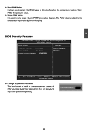
... Supervisor Password : Not Installed Enter or change supervisor password. BIOS Security Features CMOS Setup Utility - Enter New Password : 43 3 ► Start PWM Value It allows you to the temperature input value by linear changing. Change Supervisor Password [Press Enter] Move Enter:Select +/-/:Value F10:Save ESC:Exit F1:General Help F9:Optimized Defaults ► Change Supervisor Password This item is used to set an initial PWM value to drive the fan when the temperature reaches "Start PWM Temperature...
... Supervisor Password : Not Installed Enter or change supervisor password. BIOS Security Features CMOS Setup Utility - Enter New Password : 43 3 ► Start PWM Value It allows you to the temperature input value by linear changing. Change Supervisor Password [Press Enter] Move Enter:Select +/-/:Value F10:Save ESC:Exit F1:General Help F9:Optimized Defaults ► Change Supervisor Password This item is used to set an initial PWM value to drive the fan when the temperature reaches "Start PWM Temperature...
User manual
Page 54
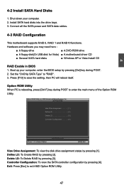
...; A floppy drive ■ A DVD-ROM drive ■ A floppy disk(Or USB disk for Vista) ■ A motherboard driver CD ■ Several SATA hard disks ■ Windows XP or Vista Install CD RAID Enable in BIOS 1. Press [F10] to enter the main menu of the Option ROM Utility. Option ROM Utility When PC is rebooting, press [Ctrl-F] key during POST. 2. Define LD: To Create RAID by pressing [4]. Controller Configuration: To view the SATA controller configuration by pressing [2]. Connect all the SATA power and SATA data cables. 4-3 RAID Configuration This motherboard supports RAID...
...; A floppy drive ■ A DVD-ROM drive ■ A floppy disk(Or USB disk for Vista) ■ A motherboard driver CD ■ Several SATA hard disks ■ Windows XP or Vista Install CD RAID Enable in BIOS 1. Press [F10] to enter the main menu of the Option ROM Utility. Option ROM Utility When PC is rebooting, press [Ctrl-F] key during POST. 2. Define LD: To Create RAID by pressing [4]. Controller Configuration: To view the SATA controller configuration by pressing [2]. Connect all the SATA power and SATA data cables. 4-3 RAID Configuration This motherboard supports RAID...
User manual
Page 56
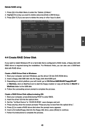
... or other key to abort... 4-4 Create RAID Driver Disk If you can also use a USB flash disk with RAID driver is required during POST to RAID mode, a floppy disk with RAID driver. Depending on which platform your computer and start the floppy creation or copy all the files in the disk! Boot your will install, go to CD:\Driver\AMD\RAID\Floppy\WinXP or WinVista, click on a hard disk that is configured to enter BIOS. 2. 4 Delete RAID array 1. Option ROM Utility (c) 2008 Advanced Micro Devices, Inc. [ View...
... or other key to abort... 4-4 Create RAID Driver Disk If you can also use a USB flash disk with RAID driver is required during POST to RAID mode, a floppy disk with RAID driver. Depending on which platform your computer and start the floppy creation or copy all the files in the disk! Boot your will install, go to CD:\Driver\AMD\RAID\Floppy\WinXP or WinVista, click on a hard disk that is configured to enter BIOS. 2. 4 Delete RAID array 1. Option ROM Utility (c) 2008 Advanced Micro Devices, Inc. [ View...


